Archive
Pre-stressed concrete canopy analysis and design verification. Destined to fail?!
My current task on site is the construction of four pre-stressed concrete canopies (locations in fig 1 below). At first I wasn’t expecting any engineering challenges; however, they have offered some valuable experience in first principle analysis, contracts, building techniques and safety in design (AUS equivalent of CDM).

Figure 1 – Location of four pre-stressed concrete canopies to be constructed.
The Canopy Structure and load path.
All canopies will be constructed in-situ and off formwork to a class 2 finish as specified by the Architect. The canopy slab is reinforced concrete with post tensioning tendons running between the columns. At the edge of each slab, on the tip of the cantilever, is an architectural trim that weighs an additional 1.5 tons. The columns are also reinforced concrete and transfer the loads through to a reinforced concrete pad footing. The loads are then transferred into the ground using helical/screw piles which have already been constructed. A plan view of Canopy 01 can be seen in figure 2 and a typical section through the canopy can be seen in figure 3.

Figure 2 – Plan view of Canopy 01.

Figure 3 – Typical section through the pre-stressed canopy. Radial line to be used for analysis.
Contractual Arrangements
The Roundhouse project and the Science and Engineering Building (SEB) Project have been executed under two different contracts. The SEB has been procured under a Design and Construct (D&C) contract, whereas the Roundhouse is part of a two stage Managing Contractor (MC) contract. The first stage of this contract was for the Roundhouse works and the second stage is for the external landscaping, referred to as the Public Domain works. Whilst the MC contract means that the principle has final authority on all design decisions and appointments of subcontractors, the second stage is still in the Early Contractor Involvement (ECI) stage, where MPX are essentially coordinating the design process, without carrying any liability for the final design. Stage 1 of the contract is essentially a traditional construct only, where the 100% detailed design was provided by the principle and the principal’s consultants. Therefore, MPX have no liability for the design and only review the drawings on a buildability basis. However, when there are concerns over the design, a request for information (RFI) can be raised to seek further approval of design.
The Issues
1. The structural consultant’s scope included the design of all elements apart from the screw piles, which were specified by the groundworks subcontractor’s (FCC) specialist consultant; Helcon Contracting Australia.
2. Concerns over the working loads created by the cantilevered slab on the foundation piles, including the impact of the stainless steel trims. The stainless steel trims were an architectural design variation and were not included in the structural consultant’s original calculations. The working loads specified by the structural consultant were 350 KN (SP2 – Compression pile) and 175KN (SP3 Tension pile) as shown in figure 4.
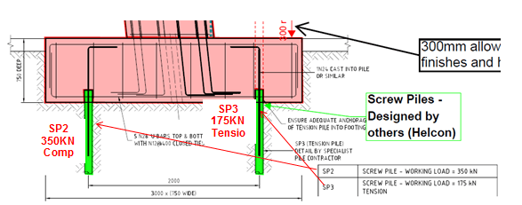
Figure 4 – Detailed section through canopy footing. 2 screw piles are designed to deal with moment created by the cantilever. Working loads specified by structural consultant shown.
3. No pile design calculations were received by MPX from Helcon for the screw piles. Helcon only specified the section geometry. Torque and depth readings were submitted as part of the inspection and testing plan (ITP) during construction, which Helcon used to produce a certificate of compliance. My primary concern was the depth of the screw piles. The site record shows that the depths were taken from ground level; however, the actual length of pile in the ground would be much less as illustrated in figure 4. After the footings have been constructed, the actual length of pile in the ground would be reduced to 3.35 metres.
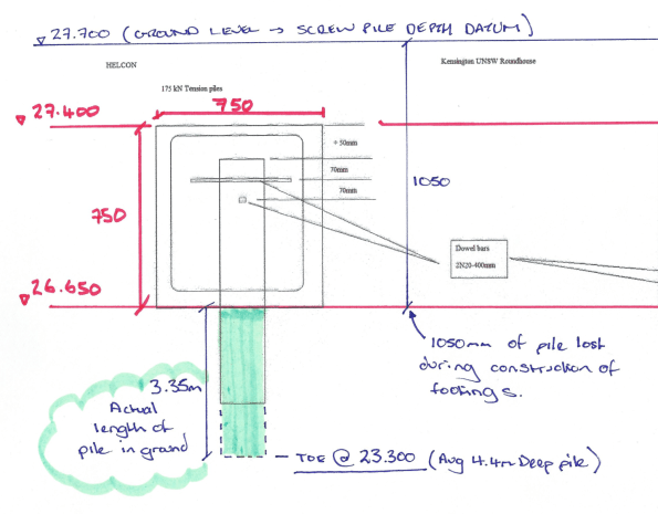
Figure 5 – RLs (AHD) for footing and pile depths. Screw pile records were taken from existing ground level.
Analysis (simple radial slice through the structure).
My aim was to ultimately determine if the structure would stand up! In order to do so, I did the following:
1. Analysis of the cantilever slab in order to calculate the maximum possible moment and axial load transmitted into the columns. The working loads in the screw piles could then be determined with a simple FBD.
2. Complete design verification of the screw piles by calculating the ultimate capacity and also determine theoretical ultimate capacity based on torque readings taken on site.
3. Compare working load vs ultimate capacity.
In order to determine the maximum moment created by the cantilever slab, I assumed that all loads from the slab are transferred to a column strip that will be modelled as a concrete beam. The middle column will be the worst case for Canopy 1 as shown in figure 6; the orange area indicates the section of slab that will be transferred to the beam strip highlighted in pink.

Figure 6 – Area of slab assumed to be transferred to notional beam highlighted in pink.
Design UDL = 83 KN/m (plus 6 KN PL at end of cantilever)
Cantilever slab analysis determined that the axial load in the column is 500 KN and the balance of the bending moment transferred to head of column is 487 KNm. The stainless steel trim only creates 5 percent of the total moment created (24KNm) and therefore its additional load is not overly critical.
Therefore:
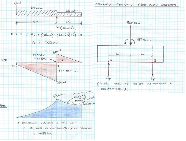
Figure 7 – Cantilever slab analysis and FBD for base of footing.
∑M @ A = 0 Therefore, (500 x 1) – 487 + (Tp x 2) = 0
SP3 = 6.5 KN (Compression)
∑V = 0 Therefore, Cp + 6.5 – 500
SP2 = 494 KN (Compression) > 350 KN
! WORKING LOADS GREATER THAN SPECIFIED BY STRUCTURAL CONSULTANT!
Screw pile estimate of ultimate design capacity.
The screw piles installed for the concrete canopy footings only have a single helix of 350 mm in diameter and the shaft diameter is 114 mm. An illustration of the screw piles used for the canopy footings can be seen in figure 8 below.

Figure 8 – Geometry of screw pile used for footings. Single helix at the toe of the pile.
Compression capacity (SP2 piles)
The ultimate compression capacities of the piles were obtained using effective stress analysis as follows:
Qult = AH (σv’ x Nq + 0.5 x y’ x B x Ny’)
where:
AH = Surface area of helical base plate
σv’ = vertical effective stress at the level of the helix/toe (D) = y’ x Depth.
Nq and Ny = bearing capacity factors
B = diameter of helical plate
y’ = effective unit weight of soil
GWL below toe of pile, so pore pressures assumed to be zero.
Therefore,
Nq (VD Sand φ’ = 37) = 40
Ny = 62
AH = π x r² = 96200 mm² (0.096 m²)
σv’ = σ – u = (16 x 0.65) + (17 x 1) + (18 x 1) + (19 x 0.7) – u (o – no pore pressure) = 57.7 KN/m²
B = 0.35 m
y’ = 19 KN/m³
Qult = 0.096 ((58 x 40) + (0.5 x 19 x 0.35 x 62))
= 0.096 (2320 + 206)
= 242 KN in compression < 350 KN Specified & < 494 KN working load calculated (FAIL)
If, full depth pile from ground level as recorded in ITP i.e. pile is 4.5 m in full length.
σv’ = 76 KN/m²
then Q ult = 0.096 (3040 +206)
= 311 KN < 350 KN Specified 494 KN working load calculated (Still FAIL)
(Shaft resistance ignored as it contributes very little to the ultimate capacity).
Screw pile capacity based on torque readings
The torque readings taken during installation appear to be the only basis for confirming the design capacity of the screw piles. In short, capacity of pile based on torque reading is:
Qult = kt x T (Kt = Torque correlation factor)
= 18 X 20000 = 360 KN > 350 KN specified working load (OK)
< 494 KN working loads calculated (FAIL)
Summary
Maximum working load from radial slice analysis 494 KN (Compression)
Maximum working load specified by Structural Engineer 350 KN (Compression)
Maximum Compression Capacity of screw pile 311 KN (FAIL)
Compression capacity of pile based on torque 360 KN (FAIL)
Questions for the group
By modelling the structure as a simple slice on a radial line, my calculations suggest that the structure will fail!
My working loads greatly exceed the structural engineer’s estimates and the capacities calculated. I think that my analysis is the extreme upper bound model and loads could be overestimated? Am I missing something on this one?
Although the capacities of the pile based on torque and effective stress analysis are relatively close, by only assuming that the top of the helix is providing resistance, I suspect that my calculation of screw pile capacity is underestimated.
