Pre-stressed concrete canopy analysis and design verification. Destined to fail?!
My current task on site is the construction of four pre-stressed concrete canopies (locations in fig 1 below). At first I wasn’t expecting any engineering challenges; however, they have offered some valuable experience in first principle analysis, contracts, building techniques and safety in design (AUS equivalent of CDM).

Figure 1 – Location of four pre-stressed concrete canopies to be constructed.
The Canopy Structure and load path.
All canopies will be constructed in-situ and off formwork to a class 2 finish as specified by the Architect. The canopy slab is reinforced concrete with post tensioning tendons running between the columns. At the edge of each slab, on the tip of the cantilever, is an architectural trim that weighs an additional 1.5 tons. The columns are also reinforced concrete and transfer the loads through to a reinforced concrete pad footing. The loads are then transferred into the ground using helical/screw piles which have already been constructed. A plan view of Canopy 01 can be seen in figure 2 and a typical section through the canopy can be seen in figure 3.

Figure 2 – Plan view of Canopy 01.

Figure 3 – Typical section through the pre-stressed canopy. Radial line to be used for analysis.
Contractual Arrangements
The Roundhouse project and the Science and Engineering Building (SEB) Project have been executed under two different contracts. The SEB has been procured under a Design and Construct (D&C) contract, whereas the Roundhouse is part of a two stage Managing Contractor (MC) contract. The first stage of this contract was for the Roundhouse works and the second stage is for the external landscaping, referred to as the Public Domain works. Whilst the MC contract means that the principle has final authority on all design decisions and appointments of subcontractors, the second stage is still in the Early Contractor Involvement (ECI) stage, where MPX are essentially coordinating the design process, without carrying any liability for the final design. Stage 1 of the contract is essentially a traditional construct only, where the 100% detailed design was provided by the principle and the principal’s consultants. Therefore, MPX have no liability for the design and only review the drawings on a buildability basis. However, when there are concerns over the design, a request for information (RFI) can be raised to seek further approval of design.
The Issues
1. The structural consultant’s scope included the design of all elements apart from the screw piles, which were specified by the groundworks subcontractor’s (FCC) specialist consultant; Helcon Contracting Australia.
2. Concerns over the working loads created by the cantilevered slab on the foundation piles, including the impact of the stainless steel trims. The stainless steel trims were an architectural design variation and were not included in the structural consultant’s original calculations. The working loads specified by the structural consultant were 350 KN (SP2 – Compression pile) and 175KN (SP3 Tension pile) as shown in figure 4.
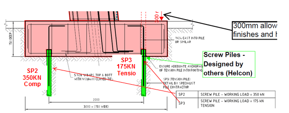
Figure 4 – Detailed section through canopy footing. 2 screw piles are designed to deal with moment created by the cantilever. Working loads specified by structural consultant shown.
3. No pile design calculations were received by MPX from Helcon for the screw piles. Helcon only specified the section geometry. Torque and depth readings were submitted as part of the inspection and testing plan (ITP) during construction, which Helcon used to produce a certificate of compliance. My primary concern was the depth of the screw piles. The site record shows that the depths were taken from ground level; however, the actual length of pile in the ground would be much less as illustrated in figure 4. After the footings have been constructed, the actual length of pile in the ground would be reduced to 3.35 metres.
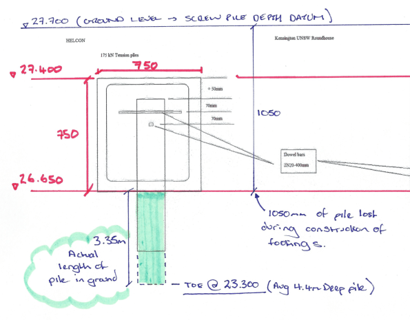
Figure 5 – RLs (AHD) for footing and pile depths. Screw pile records were taken from existing ground level.
Analysis (simple radial slice through the structure).
My aim was to ultimately determine if the structure would stand up! In order to do so, I did the following:
1. Analysis of the cantilever slab in order to calculate the maximum possible moment and axial load transmitted into the columns. The working loads in the screw piles could then be determined with a simple FBD.
2. Complete design verification of the screw piles by calculating the ultimate capacity and also determine theoretical ultimate capacity based on torque readings taken on site.
3. Compare working load vs ultimate capacity.
In order to determine the maximum moment created by the cantilever slab, I assumed that all loads from the slab are transferred to a column strip that will be modelled as a concrete beam. The middle column will be the worst case for Canopy 1 as shown in figure 6; the orange area indicates the section of slab that will be transferred to the beam strip highlighted in pink.

Figure 6 – Area of slab assumed to be transferred to notional beam highlighted in pink.
Design UDL = 83 KN/m (plus 6 KN PL at end of cantilever)
Cantilever slab analysis determined that the axial load in the column is 500 KN and the balance of the bending moment transferred to head of column is 487 KNm. The stainless steel trim only creates 5 percent of the total moment created (24KNm) and therefore its additional load is not overly critical.
Therefore:
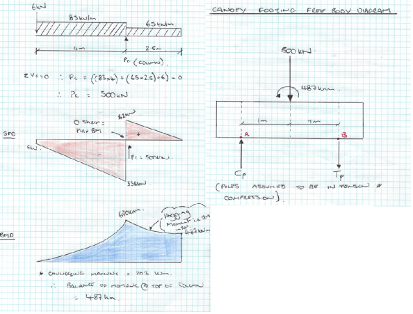
Figure 7 – Cantilever slab analysis and FBD for base of footing.
∑M @ A = 0 Therefore, (500 x 1) – 487 + (Tp x 2) = 0
SP3 = 6.5 KN (Compression)
∑V = 0 Therefore, Cp + 6.5 – 500
SP2 = 494 KN (Compression) > 350 KN
! WORKING LOADS GREATER THAN SPECIFIED BY STRUCTURAL CONSULTANT!
Screw pile estimate of ultimate design capacity.
The screw piles installed for the concrete canopy footings only have a single helix of 350 mm in diameter and the shaft diameter is 114 mm. An illustration of the screw piles used for the canopy footings can be seen in figure 8 below.

Figure 8 – Geometry of screw pile used for footings. Single helix at the toe of the pile.
Compression capacity (SP2 piles)
The ultimate compression capacities of the piles were obtained using effective stress analysis as follows:
Qult = AH (σv’ x Nq + 0.5 x y’ x B x Ny’)
where:
AH = Surface area of helical base plate
σv’ = vertical effective stress at the level of the helix/toe (D) = y’ x Depth.
Nq and Ny = bearing capacity factors
B = diameter of helical plate
y’ = effective unit weight of soil
GWL below toe of pile, so pore pressures assumed to be zero.
Therefore,
Nq (VD Sand φ’ = 37) = 40
Ny = 62
AH = π x r² = 96200 mm² (0.096 m²)
σv’ = σ – u = (16 x 0.65) + (17 x 1) + (18 x 1) + (19 x 0.7) – u (o – no pore pressure) = 57.7 KN/m²
B = 0.35 m
y’ = 19 KN/m³
Qult = 0.096 ((58 x 40) + (0.5 x 19 x 0.35 x 62))
= 0.096 (2320 + 206)
= 242 KN in compression < 350 KN Specified & < 494 KN working load calculated (FAIL)
If, full depth pile from ground level as recorded in ITP i.e. pile is 4.5 m in full length.
σv’ = 76 KN/m²
then Q ult = 0.096 (3040 +206)
= 311 KN < 350 KN Specified 494 KN working load calculated (Still FAIL)
(Shaft resistance ignored as it contributes very little to the ultimate capacity).
Screw pile capacity based on torque readings
The torque readings taken during installation appear to be the only basis for confirming the design capacity of the screw piles. In short, capacity of pile based on torque reading is:
Qult = kt x T (Kt = Torque correlation factor)
= 18 X 20000 = 360 KN > 350 KN specified working load (OK)
< 494 KN working loads calculated (FAIL)
Summary
Maximum working load from radial slice analysis 494 KN (Compression)
Maximum working load specified by Structural Engineer 350 KN (Compression)
Maximum Compression Capacity of screw pile 311 KN (FAIL)
Compression capacity of pile based on torque 360 KN (FAIL)
Questions for the group
By modelling the structure as a simple slice on a radial line, my calculations suggest that the structure will fail!
My working loads greatly exceed the structural engineer’s estimates and the capacities calculated. I think that my analysis is the extreme upper bound model and loads could be overestimated? Am I missing something on this one?
Although the capacities of the pile based on torque and effective stress analysis are relatively close, by only assuming that the top of the helix is providing resistance, I suspect that my calculation of screw pile capacity is underestimated.

Good read mate. I think you’re right about the underestimation of the helical pile. I was wondering if using the entire upper area of the helix would be correct. Doubling the area roughly gives 600kN for Qult – if the pile was at the correct depth.
It seems a bit of a mistake if the depth of embedment was less than the design stated. This would, as you said, reduce the available capacity. You’d think they would have an extension piece to be cast into the slab if this situation presented itself. Where does this leave you contractually? Is it out of spec now that the length is wrong?
Cheers, Dan
Thanks for response Dan. Yeah, using just the top section only for capacity is an underestimate. I have found some examples where they assume that the surface area of the entire cone at the toe provides resistance. Based on this I got 740 KN capacity.
On the embedment depth, after discussions with the subcontractor, Helcon specified the minimum torque reading required and a depth of 4.5m. However, this wasn’t officially specified in any documentation and as I say, no calculations were provided. It’s interesting though that the shaft resistance doesn’t provide much capacity at all and the depth isn’t the most critical element. In fact, knowing what soil conditions are above or below the toe (depending on if tension or compression pile) is most critical. Torque readings should’ve been taken for the last metre of drivingto establish the average installation torque (determined by averaging the last section of driving equal to dia of pile x 3). This wasn’t done.
Contractually it is an interesting one. The contract is construct only and therefore all design should come from the principle/principle’s consultants and MPX should hold no liability for design. Ford Civil contracting were the subcontractor and they used Helcon as their consultant. I raised an RFI on Aconex (Aconex is an online system that tracks and records all correspondence between stakeholders) to seek approval from Helcon based on the current conditions. They provided a certificate of compliance for the piles and I forwarded this onto the principle’s consultant for his approval, thereby passing the liability onto them.
Cheers, Al
Yes you think that they would be liable to quality assure their work and provide the certificate without prompting from you. Seems like a risk giving you a certificate if they don’t have the drill log to back it up.
I looked at a few helical piles and they often have a helix at the toe and halfway up the shaft.
Your means of contractual risk is the same as the version used here, called CEMAR which is NEC specific.
Al,
I found this quite interesting. Out of interest what have you done in respect of the partial factors both for the applied load and for the geotechnical parameters?
Also, after reading another document (the link is below), it states that the resistance to tension is the same as compression for a deep pile. It classifies deep as 10x the diameter, so in your case greater than 3.5m. Now that your depth was reduced to below 3.5m this must affect the tension design capacity of your piles. Has anything been said about this?
H
Click to access Quick-Design-Guide-for-Screw-Piles-and-Helical-Anchors-Short-VErsion1.pdf
Good blog Al, interesting stuff. I read an article on these but I can’t find it now, these would be good for military use. Simple and cheap. Good thesis in here if testing data can be obtained.
The canopy tapers from 300mm to 170mm, have you assumed an average thickness? 0.3 x 8 x 24 =57.6kN/m you have 83kN/m is there a load factor here? 1.4? Modelling a linearly variable UDL would reduce the moment significantly.
The calculation on end bearing is very sensitive to Nq, where did 40 come from?
Not part of your blog but the post tensionwith radial tendons is interesting, are they staggering the jacking points. Ignore this if you have not been involved.
I’m sure Jon will enjoy this one.
Good stuff all the same.
Cheers Henry and Brad. Hopefully answers to all your questions below:
1. For calculating the design values of the UDL I did assume an average thickness in the slab of 250mm. I see your point on this one Brad; the thinner sections are further from the column, therefore my moments will be larger because I’ve assumed 250mm throughout.
I crunched some numbers for a linear UDL and got a slightly smaller moment of 430Knm, but not much smaller than previous moment of 490Knm. I think that I may be getting confused with ULS design and SLS design? Is the working load specified by the structural consultant unfactored? After doing some calculations for characteristic loads only, I get a moment of 365 KNm and load for the pile of 378 KN Comp (much closer to 350 KN working load specified by engineer).
I did use the standard partial factors from UK NA; 1.35 (perm actions) and 1.5 (variable actions). I didn’t use any GEO limit state factors for Phi’, I only used the bearing capacity factors Nq and Ny.
2. I also assumed a Qk of 1.5 KN/m2 (Typical Floor loading from EC). Although not a floor, I wanted to assume that access will be required for maintenance.
3. On the depth for tension capacity of pile, the 10 x diameter seems like a reasonable rule of thumb. Is that diameter of shaft or helix? Assuming it’s Helix diameter, the piles would require a depth of 3.5m to prevent uplift. So just short at 3.35m! I found something similar (Harnish 2015) that stated embedment depth (H) /Helical diameter (D) should be greater than 5. For these piles H/D = 3.35/0.35 = 9 > 5 (So ok!). My calculations also found that neither of the piles was in tension, even with imposed load only on large cantilever (would be interesting to impact of placing a greater load at tip of cantilever to simulate a person working on the canopy).
As Brad alluded to in one of his blogs, my calculations raised some issues but would not be used to officially mitigate any risks here. This is a construct only contract and therefore all design risk is passed to principle’s consultants. I requested approvals based on as-built conditions from Helcon and structural engineer, which they provided in writing.
4. To get Nq I used an equation by Lutenegger; Nq = 0.5 x (12 x phi’)^(phi’/54). This is for drained condition using 37 deg for phi’ (all geo properties taken from Coffey GDR). Jon’s equation for Nq in shallow foundations notes confused me and I was getting much smaller values which, as you say Brad, greatly reduced the capacity of the pile! I think that determining what area of the pile toe is providing capacity is key. If you assume that the entire surface area of the helical cone is providing resistance, the capacity increases to 757 KN (compared to 242 KN with just the top plate),
5. The jacking points weren’t staggered! There’s a single jacking point at either end of the 2 tendons. What is the reason for staggering the stressing pans on a radius? Do you get increased losses or are there serviceability issues?
Thanks, Al
I’m not sure what they do down under but EC has two combination which need to be satisfied at ULS. Combination 1 you factor how you have and leave the soil parameters, combination 2 1.0 x DL/1.35 x LL, factor the soil parameters and factor the resistance. For piles I think combination 2 is dominate. But a much simpler way is to divide the pile capacity by 3 and compare to unfactored loads.
For the effective area, is a specific type of pile specified by the designer? The must be an area provided or specific pile manufacture stated by the designer else how would the contractor know?
I hadn’t looked at the layout correctly hence the staggered question. The stressing loads will result in bending about the weak axis of the column but I suspect this is neglecting.
Cheers Al
Nice one Al. A really neat piece of engineering to look at, no clutter but lots going on! Do you think that the prestressing is doing anything special here? Does the whole canopy become stiffer and act as a single item or can it twist? If this is a single item then you don’t have to look at it as a simple slice (conservative but falling foul of your limits) and can look at it as a whole structure. Your Fig 6 sin’t rendering this side of the wire but, if you take the whole thing (i.e. fig 3 but wrap the canopy back on itself), the centroid of the canopy is closer to your column than you thought and the lever arm for the piles is increased by considering all three footings relative to the whole structure. Add to this Brads point about tapering and that access for maintenance is 06.kNm^2 and things get better. Innovative use of prestress to create advantageous stiffness in bending and torsion. I’m also guessing that the piles go into compression due to N and increased or reduced compression arising from M but don’t develop tension, albeit that the rear most two of the whole thing might now come closer to it than you thought?
Cheers Brad. You’re absolutely right about DC2 being dominant. Based on your suggestion to taper the UDL action, combined with Rich’s advice to make Qk 0.6 KN/m^2; I get the following reactions/moments and maximum compression loads for the screw piles:
EC – UK Approach
DC1 – yG = 1.35 & yQ = 1.5 (soil parameters not changed)
N = 428 KN M = 323 KNm
Max Load in Pile = 375 KN (Compression)
DC2 – yG = 1.00 & yQ = 1.3 (phi’ / 1.25 = 37/1.25 = 30)
N = 362 KN M = 225 KNm
Max Load in Pile = 293 KN (Compression)
Helcon pile specification
The pile was specified by Helcon as seen in figure 8 (114 diameter with a multi-fin helix at the toe). Helcon provided the subcontractor (Ford Civil) with this head detail and the shaft diameter as a spec.
I spoke with a Helcon designer today; although reluctant to provide their exact design, he explained that the each fin/plate is assumed to be providing resistance (Total of 3 complete fins in this case)
Therefore, for these piles you would have a total surface area of = 0.2 m^2
Pile Capacity
Because Nq and Ny are a function of phi’, using DC2 greatly reduces the pile capacity as you say.
For phi’ = 37 Nq = 40 Ny = 62
For DC2, Phi’ = 30 therefore, Nq = 18.4 Ny = 22
I found a table (Vesic) that corroborated these bearing capacity factors (Nq and Ny) based on the phi’ values.
So….Pile capacities based on eff stress analysis
DC1 – 0.2 (58 x 40) + (0.5 x 19 x 0.35 x 62)
= 505 KN > 375 KN (PASS)
DC2 – 0.2 (58 x 18.4) + (0.5 x 19 x 0.35 x 22)
= 228 KN < 293 KN (FAIL)
Thanks Rich, it’s good to hear that my method is conservative because we are stripping canopy 01 next week! I am not entirely sure what hand calculations I could do to analyse as a complete structure. Which of these methods would work? Yield line analysis, equivalent frame method or re-distribution of moments?
I did manage to get some results from RAM Concept software:
Middle column – N = 343 KN M = 335 KNm
– Max compression load in pile of 349 KN (very close to engineer’s 350 KN specified)
– Tension Load of 6KN
Outer columns – N = 187 KN M = 239 KNm
– Max compression load in pile of 213 KN (very close to engineer’s 350 KN specified)
– Tension Load of 26 KN
As you say, the two outer columns are developing tension in the rear pile because N is much smaller than the middle column but a significant moment is still generated. As a whole structure, W is at an eccentricity in both directions and therefore you will get simultaneous bending about the two principal axes. Will this create torsional moments? Is torsion critical in an indeterminate structure?
I didn’t highlight in the original post, but there is effectively a beam running between the columns in addition to the pre-stress tendons (4 N20 (top), 5 N20 (bottom) and N12 @ 200 c/c). When I calculated the area of steel in parts of the slab, the stiffest sections were the central beam between the columns and the column strips where I did my original analysis. I think the pre-stress and the beam running between the columns is working to re-distribute the bending moments and torsion but I don't fully understand this? I’ve reached the limit of my knowledge at this point!
THE AUS APPROACH TO SCREW PILE DESIGN
I also discussed the pile design with an associate geo engineer at Coffey; they are the Geo specialist across all the projects at the UNSW campus development. She referred me to Australian Standard AS2159; Piling Design and Installation.
In Australia they factor the loads and geo parameters. The design geotechnical strength (Rd,g) is calculated as the design ultimate geotechnical strength (Rd,ug) multiplied by a geotechnical strength reduction factor (φg). I commented on Eadie’s last blog about how this is determined; based on a site risk rating. On the SEB our ground engineering subcontractor employed Keller to complete all piling design and they specified a geotechnical reduction factor of 0.67 (i.e. very low risk site). When I spoke with Helcon designer he said that they always assume a geo strength reduction factor of 0.48 (this would be for a moderate to high risk site, depending on redundancy of piling system). Coffey also suggest 0.48 in GDR if no pile testing is completed.
AS 2159 provides a formulae for the ultimate geotechnical strength of a pile loaded in compression as:
Rd ug = fbAb (Can have shaft resistance but I have ignored because it’s negligible)
fb = Ultimate base stress for compression pile. Coffey recommend a design parameter for dense sand of 7000 Kpa for ultimate end bearing (fb) in their GDR.
I researched this assumption and found a report on observed vs predicted base pressure for steel screw piles (Abrammson & Yttrup 2003) which raised concerns over predictions for ultimate bearing pressure. fb values from testing were 3000 Kpa when the geotech predicted 7000Kpa! App A, Table 1, Chapter 14: Shallow foundations (Jon’s lecture notes), contains allowable bearing value for Dense Sands of > 600 KPa! Not sure what the FOS is here from Ult to Allow?
In Summary, Aus design capacities for piles would be:
Φg = 0.48
For fb = 7000 Kpa
Rdg = (7000 x 0.2) x 0.48 = 672 KN > 375 KN (Similar to EC DC1 = 505 KN)
For fb = 3000 Kpa
Rdg = (3000 x 0.2) x 0.48 = 288 KN < 375 KN (Similar to EC DC2 = 228 KN)
The estimate of qult here is critical. Based on Coffey’s recommendations of 7000 KPa (fb) and 0.48 (Φg) the piles pass.
Good stuff Al, sounds like you are doing some interesting stuff.