Phase 3 – getting the geek on!!
Hi all,
Merry Christmas, I trust like me everyone had intentions to do loads of thesis but ended up doing none.
Getting a little bored of working for a management contractor I decided to move to phase 3 mid November. I though now would be a good time to give a little update.
I’ve started at a small office which have recently branched out from Australia into the London market called BG&E. I haven’t yet worked out what that stands for, for those interested here is the website.
There are 9 in the office, 4 structural engineers, 1 BIM technician, 1 CAD technician, 2 RC detailers and me. So far the office has been doing temporary works for some of the big London contractors and some mid rise residential developments in Cyprus.
Since starting, I have been getting bits of work but as can be expected nothing substantial. I’ve outlined what type of stuff I’ve been doing.
Task 1 – Reinforcement rates
Part of a wider package with Getjar, as a second checker I used a mixture of RC intents and details to calculate tonnages for costing as part of a tender return.
Task 2 – Transfer Beams
The Broadway, London is a resi/commercial development with 6 buildings between 14 – 20 stories. The structural engineers, RBG, have detailed a steel section encased in RC as a transfer structure for a line of columns which go the hight of the structure. The step that the beams make is an architectural feature of the building creating large lobbies, see the section through below.
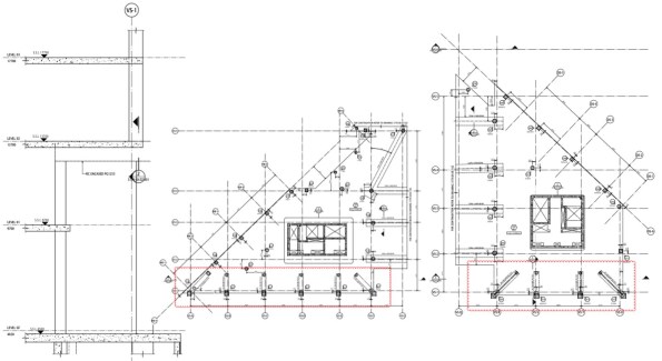
The issue was the contractors crane strategy did not have the lift capacity/radius to lift in the transfer beams. So they engages BG&E to conduct an option study, which was then given to me. There was no information on column loads, just the GAs and floor load diagrams. Unfortunately for me, the column tributary areas are different for each column and also the loads. So I did a column run-down using load reduction permitted in EC1 to get the loads at the base of the supported column. I then used a software called RAPT to ‘play’ with possible options. The most effective solution would have been to increase the depth of the beam and use normal reinforcement, however generally beams cannot be increased in depth due to the other trades. So I increased the width of the beam to 1200mm and it worked with 3 layers of 32s @ 100 (in the bottom), this was proposed to the contractor and we wait for further work. Clearly PT could have been used, but the it is not clear if the floor plates will be PT as they are c300-350mm which is thick for the spans.
Task 3 – Climbing Screens
Wembley Park, is a large resi development to the left of Wembley Stadium for those who have been recently. The contractor has won the job and is trying to work out their climbing screen and back propping strategy, the climbing screens can be seen below. This seems a little late to me, how much floor back propping is required and how quickly it can be struck must surely be known to form a programme. Unless it is a guess….
Getjar ask BG&E to conduct a concept study to see what is required for the climbing screens. Again the RC intent was not available as the design is not that advanced, all that was available was the floor plans and loading diagrams. Looking at the typical floor layout it was clear that there were three different spans. Knowing that the RC slabs would be designed for the loads in the diagrams, i.e. permanent case. I built the spans in RAPT (programme) and calculated the forces and reinforcement required. I then used this to compare to the construction case with the loading from back propping, climbing screens and a construction LL.
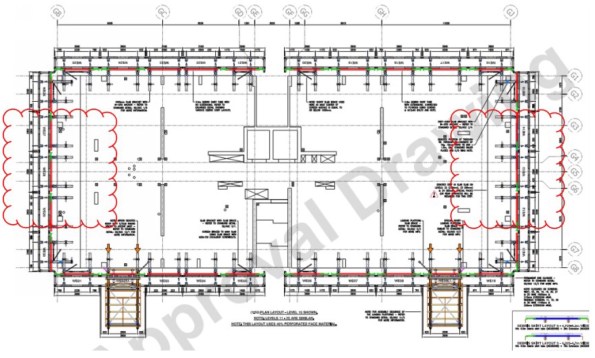
This showed that the climbing screens did not need any additional back propping, if the loads where not applied at the same times as the back propping to construct the wet deck. This is unlikely, as the buildings a residential the SDL and LL are low, 1.5Kpa each. The 250mm RC slab exerts a back propping load significantly larger than this and would need back propping over at least two floors. I calculated that for the loads to be combined the reinforcement would need increasing locally by up to 15% above that required in the perm case. It is now up to Getjar to do a cost exercise, material cost v programme to see which is preferred.
As a side note I also check deflections to ensure deflections under construction loading where not excessive. Whilst doing so I noticed that one of the larger spans was deflecting 30mm under permeant loads which is over span/250, which would be bad for internal finishes. I raised this to the contractor and this may come back to BG&E to design a PT slab for this area.
Task 4 – Tower Crane Grillage Cat 3 Check
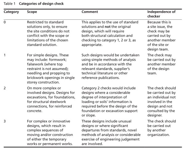
The foundations for tower cranes are generally considered temporary works and as such fall under the guidance of BS 5975. The level of the required design check is outlined generally on the complexity and consequence of a failure, the category’s can be seen below.
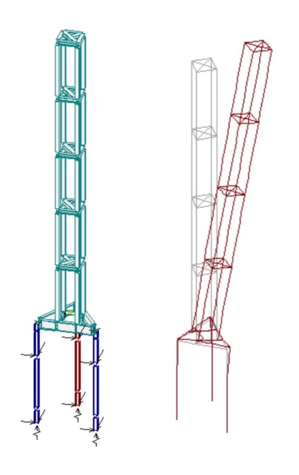
My previous project, One Nine Elms has 5 tower cranes, all supported off grillage which is more complex than normal, I have discussed one at length in a previous post. Clearly the consequence of a failure could be dire, for those with a strong stomach YouTube ‘tower crane collapse Mecca’. It is also bad for business, failures are very public affairs and to make them worst developers/main contractors like to put their company logo on the crane. Anyway, a cat 3 check should be conduct by a person outside of the organisation which did the design. The check should be done without the calculations, just the drawings and any pertinent information, loading etc etc. This task was given to me with the direction to see how far I get…… shit. I was given some information about the crane and Carey’s design drawings.
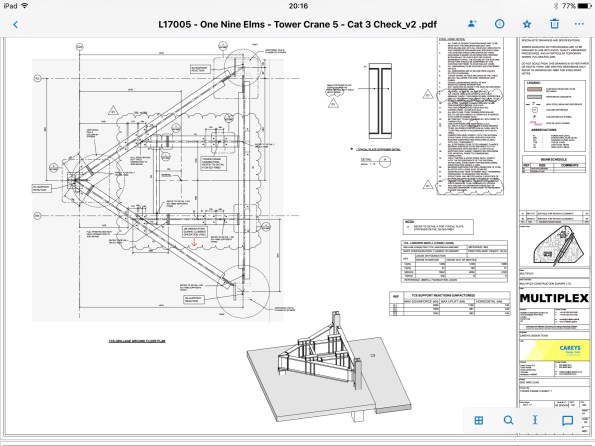
My first start was to check Carey’s had used the correct loads from the crane supplier, it was slightly concerning to find they had missed the most onerous case a storm hitting the front of the jib. I built the steel grillage in a software called Microstran (similar to STAAD) and applied the loads with a number of different combinations to get forces and deflections. I then realised I have forgotten everything Neil taught us about steel and spent a day going back through section and member checks by hand, the software also does a check which it useful. Clearly somebody sits in the crane cab so a large differential deflections between the legs gets amplified higher up. I also believe the crane suppliers factor up the loads they provide, as a way of reducing deflections to stop Pdelta effects.
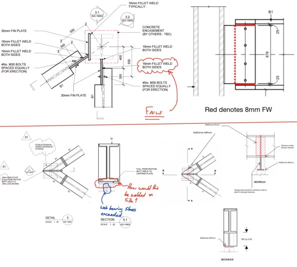
By far the most difficult check was the connections, with my main issue being whether to fix or pin the members at the joint. I found the 16mm FW on the fin plate insufficient by some margin in either case and suggested an alternative solution. The solution (see below top) uses and 8mm FW which can also be done with one pass so Saving labour costs. In checking the apex type of connection I found that the plate welded to the plunge column plate resulted in a bearing stress great than the capacity of the section and would also be difficult to weld on site. After some head scratching and advice I came to the solution below.
Quite a bit if stuff in a couple of weeks and I am learning lots quickly. One thing I have noticed is that the engineers do almost everything on some form of analysis software, Excel and Bluebeam with very little being done by hand.
I hope I haven’t bored everybody to much but you already know I’m a geek.
Brad
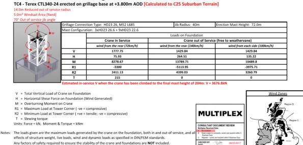
James, these are the loads supplier by Select for a 70m tower crane. The overturning moment drops to almost nothing when the crane is tied.

Cheers Brad.
How are you finding the software (RAPT)? Do you think you’ll use it in future on RE tasks?
I’ll upload some stuff about my job once I get past this week.
Ok to be honest, I tend to have YouTube open and watch a tutorial. The difficulty is generally there are a lot of variables and I don’t have a scooby what they do.
I’ve found Microstran and Limcon the most useful. Microstran is like STAAD Pro but more user friendly. Limcon is a connection programme which is handy for resolving forces for welds. Excel is still the most useful, it can do some pretty funky stuff and allows change quickly.
Some offices use TEDDS I hear they have it at 170 and it’s mean to be quite good.
It’ll be good to see what people are up to.
Brad
Thanks for the Limcon recommendation. I’m checking reinforcement cages for lifting at the minute to find how many welds they need. Might be a useful thing. Looking at Mr George’s notes to see what a reinforcement drawing means. ..
Cheers
Hi Brad, Happy New Year,
I’m still with John Holland, but I’m working closely with BG&E in the design on a new 348m access bridge into a new rail yard, great bunch of chaps.
I was interested in the wind action acting on the tower crane in a storm. I have read that SOP’s for operating a tower crane is to release the slew brakes and to leave the trolley in the inner position with hooked raised with no load during a storm. This then allows the crane to ‘weather-vane’. Equally important, the foundation must be properly designed, constructed, and have sufficient drainage.
Theoretically the surface area of the front jib is much larger than the rear jib, the front jib will follow the wind direction, and the rear jib will point against the wind. This orientation minimises the surface area thereby reducing the wind pressure exerted on the crane.
Cranes normally collapse when the operator fails to follow instructions – human error.
Also, tower cranes are substantially counter weighted. A typical tower crane with no hook load will have a reverse moment which is equal to the forward moment when the crane has its full design load at max reach. The tower crane is balanced with no moment applied to the foundations when the crane has half its full design hook load at its max reach.
The combination of jib direction, along with the substantial counter-weights and the crane free to weather-vane all comes into helping a tower crane resist high winds.
Is this perhaps why the design team had ignored wind action or perhaps it was not the leading action?
Also, put a requirement in your design that the tower crane operators don’t attach a huge advertising sign to the crane, this could cause havoc with wind loading calculations.
Hi James, when are you moving? Yea I hear they are a big company down under, but they are new to the UK. There is more than enough to keep me interested at the moment. I looked at wind loading on tower cranes for a TMR, what is interesting is that crane suppliers often provide increased loads than you would expect for a given storm. I have come to the conclusion that this is a mechanism to control deflections to negate any pdelta effects.
The slew lock is important if the cranes are not deconflicted in height. Put as you say dangerous in the crane is not designed for it. Those that don’t have a little sail high on the jib to ‘blow’ the crane round in the event of a storm. The three design case you check in design is in service and then two out of service, i.e. In a storm. The two case are 140km/h wind to the rear and 100km/h to either side. I imaging that winds could be high in Oz particularly around the N coast. Interesting stuff though.
To answer your question at the end I don’t think they did it on purpose. If you get the chance to look at the design of crane supports you’ll soon realise the wind is the dominant factor, if it is a tall crane. If put a screen shot of the loads for a 70m crane the out of service moment due to wind is 13789kNm the legs are 2.2m apart, this gives a reaction of about 5MN!!
I agree with the sign, this is normally dealt with between the contractor and crane supplier. It turns out it’s very bad for crane suppliers if they have a crane failure, so they tend to be hot on it.
Brad, that looks like a good start for Phase 3 and interesting stuff. I have also found the same regarding software here at Atkins. We have the Autodesk suite of software so use Revit for viewing designs and overlaying different 3D models ie architect’s to structural and Robot which is a structural analysis software. In theory you should be able to draw a model in AutoCAD, view it in Revit then structurally analyse it in Robot. I was surprised to find Robot very similar to STAADPRO in its principals.
On a different note I have just been sent the link to a new interactive version of the blue book which seems to be quite handy:
https://www.steelforlifebluebook.co.uk/
Hi Ed, I suspect that package doesn’t come cheap. How user friendly is it? I met Dan from the Stage last week. He has just moved to Charlotte Street, MPX where about to erect a 500Te crane in the road to erect a tower crane. They had not however had anyone check that the adjacent basement walls could cope with the increase lateral pressure. I think I landed on his desk on the tues for erection on the sat…….
I’m steadily collecting spreadsheets and examples of stuff. We could have a decently collection of stuff between us at the end of the course.