Temporary Works
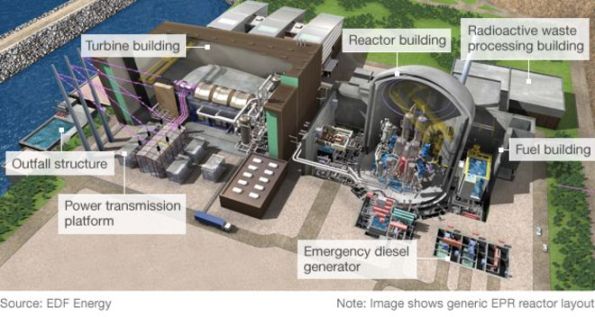
I am working in a team of 10 for the JV that has the main civils contract for Hinkley Point C. Bouygues-Laing O’Rourke (Bylor) are responsible for the structure(s) that contain the nuclear gubbins for the 3200 MWe reactors, cooling systems, and ancillary buildings. Currently circa. £2bn of contracted scope, and rising.
The TW office responds to requests for scaffold, formwork, lifting calculations and other curios from site on an ad-hoc basis. They liaise in advance with the pre-construction team (working mostly out of Paris) to design formwork and falsework systems along with bases for the 40-50 tower cranes to be installed. Large volume packages are let and managed by the TW team to supply chain companies like Sateco, Peri, Doka and Hunnebeck.
I just completed my first task which was re-working some calculations for reinforcement cage lifting and issuing the new lift schedule to site. Not quite a flume I know Ed! The cages were for the reactor inner containment structure which consists of a pre-stressed ring and conventional reinforced concrete. This forms the lower wall of the reactor building(s). I can’t put up any decent drawings or models, unfortunately. The re-working was required as the method of installation changed, separating the cages into smaller lifts.
I was surprised at the factor of safety of 1.35 x 1.2 was applied for what is 3 crane lifts. Onto the wagon, off the wagon and turned vertically prior to installation. By using some steel designers manual/StaadPro/standard beam formula I managed to reduce quite a lot of the welding on each cage. The number of ties on the cage was the critical case.
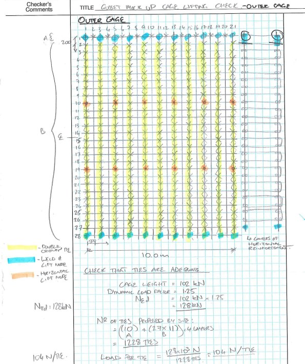
Proposed tie and weld arrangement. Still less conservative than the original design.
Ties themselves are difficult to quantify although tensile testing exists. An assumed SWL of 254N (25kg) gave a FoS of 8 from tensile test results. I couldn’t find out where that SWL was taken from. It seems rightly high in FoS terms given the risk of corrosion, human error in tying and damage. Future testing of tied wire is in the offing which should provide data for my TMR on the subject. I expect the variance between samples to be greater, and still quite difficult to pin down. However, any improvement in capacity reduces the amount of work for the steel fixers which equals fewer hunchbacks and less knackered wrists!
Working in the office is a noticeable step change from the site. Namely, that, a lot of people wear headphones all day and there are fewer threats of violence or general harassment. When I told the animals on site that I was going to work in TW they said that I’d be responsible for adding zeros to the budget and making things difficult to construct. On reviewing a small work package for welding to reinforcing cages I have observed how this can occur. I have also seen how easy it is to specify something that is overdesigned or even unsafe to construct. Particularly as they do not see many pairs of eyes before heading out the door.
I’ll hopefully have something more coherent and of note to post soon.
Dan

Sounds like you’re in a much happier place. Part of the challenge with the ties is not just the applied action but the internal distribution of forces i.e. the load paths and potential for distortion of the whole. Has this been considered?
If the tie is properly twisted you can get roughly fy/(root 3) in shear
A decent 1mm 6mm FW will give 1 kN/mm but you would need thsis to be somethign lik5 3mm min length for the thing to develop
Ok thanks John. I’ll look at the test results to see how fy/root3 compares. Rich yes, the load paths have been looked at and on top of my calculations the standard cage has a double crown tie at alternate nodes.
Dan, thanks for the post – interesting note on the tie SWL, I wasn’t aware of this previously so will be interested to hear how the testing progresses. From what I saw on site is there any specification that the lift points should be connected to the bottom cage reinforcement, or at least the bottom layer of top reinforcement? Or do you rely completely on tie strength?
James, thanks for the response. Yes for horizontally lifting the cage the lower bars on the top mat are lifted to reduce tension in the ties. However the best way to do this would be to lift from the very bottom, however this is often impractical due to bar spacing and lack of access. For lifting a wall cage into position vertically the welds act as reaction nodes to the multiple leg chains which attach to the lift beam. I’ll post a photo which will be better when I get a chance.
Good stuff Dan, this looks a lot like a D Wall cage. Maybe a little wider. These have lifting bands of 80mm x 8mm flat steel with main bars welded to it. Out of interest is this for a wall or slab? The bundled bars seem to me to be in an odd orientation, they look like they are for bending about the z axis if x is out of the page on the diagram on the left. Does this wall contain blast?
Brad, yes I’ve read about steel flats being used. Additional bars are often welded to starter bars for wall cages to rest on to ensure that the critical height dimension is achieved. The cage here is for a wall that resists blast from inside. It is a segment of a circle in plan. Resistance is achieved by a ring of post tensioning tendons.
Daaaaaaaaann – don’t understand most of what you wrote but was wondering if there were different ‘basis of design’ when working on nuclear facilities? I only ask as I’ve dealt with a couple of vendors who are certified for nuclear work and they typically have to go to the nth degree for everything.
Maurice, for TW it doesn’t seem to be much different from what we have done on course. However, traceability is a massive thing. Check sheets and QA not being in place have resulted in concrete being ripped out on several occasions – potentially a crane base that was poured by some enthusiastic Frenchmen. Welding, as I’m sure it is with you, is traceable with each weld given a unique number and documented for X-ray testing etc. The amount of signatures to pour a slab is around 30 at least. This was born of precious mistakes. Although the nth degree I think it has developed over time. Naturally it seems to have been influenced by programme prior to various fuck ups. It’s now a lot tighter.
*previous, not precious. Gollum
Thanks Dan. Sounds similar to oil and gas for completion of packages. Although I’m sure the nuclear industry is pretty savage.
From what you’ve said the management of activities in oil and gas seems a lot more rigid. For obvious reasons.