Integral Bridge Design
Now firmly settled into Phase 3, I thought it was about time I provided an update of my most recent ponderings.
I am working for Tony Gee and Partners on a new link road near Wigan. The A49 Goose Green to Westwood Park Link Road scheme comprises a new 2.3km highway to relieve congestion and provide future access to a new development – Westwood Park. The scheme consists of a new dual two lane carriageway with new non-motorised user routes, four new road bridges, two new footbridges and culvert repair works. Two new roundabouts will be built as part of the scheme to provide access and distribution into the future development of Westwood Park. The scheme provides design opportunities across highways, structures and geotechnical disciplines.
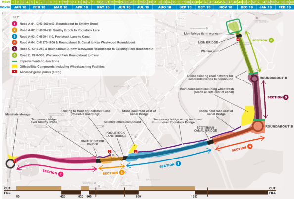
Proposed A49 Route with Route Sections & Structures
Roles – One of my current responsibilities is for the developed design of Scotsman Canal Bridge. This was tendered as an integral bridge under the ER’s. The design consisted of 8No. 1.6m deep W12, 32.3m long, precast pre-stressed concrete bridge beams supporting a 250mm thick reinforced concrete bridge deck. The bridge has a 13.7° skew. The superstructure is made integral with reinforced concrete abutments supported on reinforced earth embankments atop a 7m wide zone ground improvement.
Integral bridge design solutions (designed without any expansion joints between spans and abutments) offer a host of benefits from increased durability, reduced maintenance and lifecycle costs. However, they can pose the designer several issues to consider from the moment connect between beam and deck to the geotechnical issues of increased earth pressures and deformation behind the abutments. At the moment these are problems for future Al to overcome – so wait out for further blog posts!
A calc or two – Given the rushed nature of tenders, one of my initial tasks has been to verify the tender design for various aspects. These have included;
- Verifying the abutment pad pressures – The ground improvement works that the proposed abutments are to be sited on have a maximum uniform bearing pressure of 170KN. Assuming the carriageway dimensions in the tender and a precast manufacturer of the W12 beams a permanent load take down was achieved. The tendered ER’s stated an SV 196 variable loading requirement. From BS EN 1991-2 a Group 5 loading regime was assumed with LM1 and LM3. In the same vein as Ex Bridge, the notional lanes and load models were calculated to attain a variable load adequate for the purposes of this rough pressure check. My initial verification checks noted;
122KN (permanent) + 64KN (Variable) ≥ 170KN ∴ Not Okay
However, it is deemed that values used for verification are very conservative and so this could be satisfied later in developed design.
- Verifying Edge Beam Arrangements – As designers there is a need to design for the execution phase. One of my tasks has been to verify various edge beam arrangements for the contractor to choose as a desired install arrangement. This has involved creating beam arrangements around; beam, parapet and deck elements. From here the permanent load of the system is calculated and then the beam arrangements are checked for global stability / overturning moments allowing for wind and pedestrian effects. A summary sheet is then provided to the contractor in order to allow an informed choice of install arrangement.
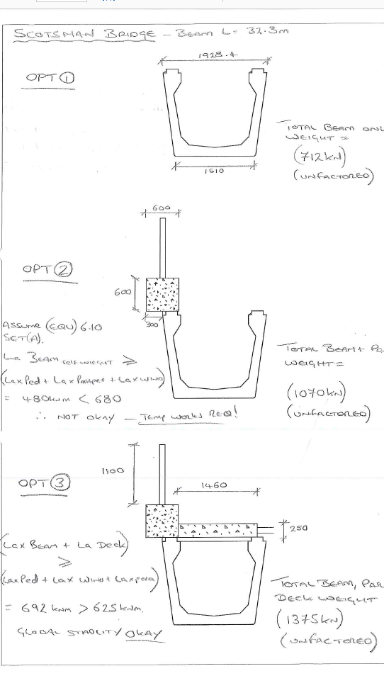
Sketch Summary sheet
I have quickly realised that in the design office communication is as important a skill as on site. Communicating assumptions and/or queries early makes for a smooth and productive design phase. However, this information also needs to be succinct and relevant to the recipient.
I hope to provide some details of the developed design in the coming months as I get to grips with LUSAS!
Al

Mr Winston. Looks like a really interesting project. I was also involved in producing some tender design calculations and you’re right about the conservative approach to design. However, in my strength checks I used the normal factors (1.35G + 1.5Q) but, the allowable deflections were conservative; span/500 was used ( AS suggest span/360 for beams). This meant that the sections would be slightly beefier for tender and would be made more efficient later on.
What factors did you use for the permanent and variable actions in your bridge abutment check? Should the bearing pressure be in KPa? Or is that converted to maximum reaction at abutment?
Hey Al,
Apologies for the slow reply.
So I assumed the use of EQU 6.10 BS EN 1990 for combination of actions and Set A figures (Table NA.A1.2(A)). From this I allocated the following values;
Beam self-weight: 0.9Gk (Permanent Favourable)
Parapet self-weight: 1.1Gk (Permanent Unfavourable)
Wind: 1.5Q k (Leading Variable)
Pedestrian: 1.5Q k (Accompanying Variable)
Regarding the query of abutment pressures, yes, this was converted to give a maximum abutment pressure. Made for an easier comparison.
Hope all is going well down under…. Looks like they are keeping you on your toes with that project!