Phase 3 – Structures Team at RBG
5 weeks down and hopefully something of value to report. It took several weeks for my brain to warm up.
Interesting to see the content of Brad and Dan’s work. The temporary works environment looks excellent in terms of variety and volume of small problems to solve.
I am now working for Robert Bird Group (RBG) in Sydney within one of their structures teams. The Sydney office contains 2 structures teams, a civil design team, and a construction engineering team (temporary works and construction methodology). I am currently working on 2 projects; University of Wollongong (UoW) and Blacktown and Mount Druitt Hospital (BMDH). UoW is in the tender design phase and BMDH is under construction.
The structures team is managed by a principal engineer, with the support of 3 associate engineers. RBG policy dictates that all associate engineers and above must be chartered engineers. Work packages are assigned to the engineers, including myself, at the team resource meeting which is held every Monday morning.
My responsibilities to date:
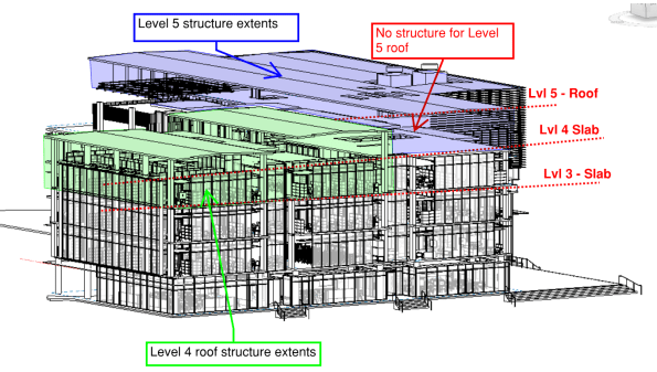
Task 1. UoW – Structural Steel Frame design on Levels 4 & 5. I was tasked to develop the concept designs for the entire level 4 and 5 structural steel roofs. In the initial stages, I had to scrutinise the architectural model in Revit as well as the architectural floor plans to produce some initial layouts for a frame. The aim was to create a frame layout that would correspond with the Architect’s floor plan but, also achieve continuity of load run-down through to the concrete frame to avoid load transfer. The level 4 roof was to be built off the level 3 slab, and the level 5 roof off the level 4 slab. You can see the extents of the steel frames for level 4 and 5 in RBG’s structural BIM model below (you can see that level 5 had no structural elements at this stage). My initial layouts were incorporated into the BIM model and the in-house draftsman created some hasty level 4 and 5 general arrangements (GA) for further design development.
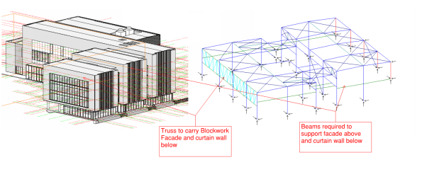
In order to simplify the analysis and design, I decided to consider level 4 & 5 separately. I used a software package called Microstran (I agree with Brad, much easier than STAAD) to complete the analysis for the indeterminate frame. The biggest challenge was ensuring that lateral stability was provided and that the frame included members to support the various architectural features (e.g. curtain walls and façade). I finally opted for horizontal and vertical bracing in order to provide lateral stability (loads eventually running back into structural slab). The image below shows my Microstran model for level 4 and the various structural elements that had to be included to support some of the architectural features.
 To create a working model, the nodes and members had to be modelled accurately in order to complete analysis. Deciding whether a connection was to be pinned or fixed was very challenging. The process helped me understand how the overall structure and individual members were behaving (e.g. tension only members, what the different connection types would be and what forces could be transferred). To simulate the interaction between the frames on level 4 and 5, I modelled the connection as pin supports.
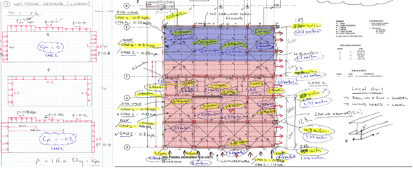
Once the associate engineer was satisfied that my model was stable, I then had to calculate the actions and create the design load combinations for the model (22 in total). This included the calculation of wind actions using Australian Standard (AS) 1170.2.2011: Wind Actions. The process was similar to EC; you work out the design pressure and your net pressure coefficients to get a KPa value (extract from my calculations below).
After calculating the actions on the structure, I then assigned section classifications to each member in the model. I started by considering the primary rafter and modelled it as a SS beam to get a ballpark BM. With the primary member assigned, I worked through the structure and reduced the section geometry as I went. I had to go back and change some of the sections, as RBG will typically use particular sections for different purposes (e.g. CHS/SHS for struts and EA for ties). With more experience, this process would be more intuitive. The image below shows my final model for level 4, the different section classifications are indicated by different colours (left image). The image on the right is my final analysis and shows the BM envelope for all load combinations. I used the results to complete strength and serviceability checks on the sections I had chosen. Australia didn’t completely copy the English on this one, they have the RED BOOK for their steel section properties and capacities. Deflections and bending capacities were satisfactory (Span/500 was used to be conservative). I did have to incorporate some fly bracing (restraints) to reduce the effective length of the main rafters; to prevent buckling in the wind suction case.

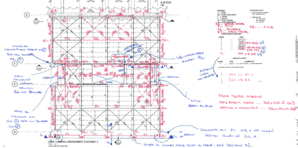
RBG subcontract the final production of structural drawings to RAMTECH software solutions in India. Therefore, I had to produce some marked up GAs and elevations to communicate my design output for final drafting (see examples of my work below). The final drawings will be issued to the competing contractors, via the client, to assist with pricing the job for tender submissions.

Task 2. BMDH – Precast concrete façade inspections. I was also tasked with overseeing the final approval and inspection of some pre-cast concrete façade panels on the BMDH. The panels are essentially SS slabs on the outside of the building. They are supported at the top of the panel by a corbel that sits on the structural slab and is pinned by a dowel connection (see image below).
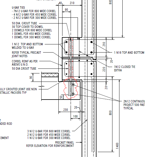
The design had already been completed for the panels and I just needed to check the details during my inspection. However, I wanted to understand how the panels were behaving and did some simple analysis to identify where the critical points for inspection were. I deducted that the shear load in the dowel connections was critical and that the critical BM would be in the corner of the panel (FBD and quick analysis below). The wind action would also create biaxial bending (so vertical and horizontal reo required in panel).


The panels were being constructed by Hanson in their factory just outside Sydney. The Architect (Jacobs) and Contractor (AW Edwards) were also present during the inspection. The reinforcement was satisfactory; however, honeycombing was identified in some of the corbels, which reduced the cover and durability of the section. Hanson will now provide a product specification and methodology for patching in those areas.


Good stuff Al, did you use the automatic design tool built into Microstran? This with the Blue/red book is very useful, I have also used the calculators on the SCI website for quick checks.
Nice Al! It’s good to get a picture of the consultant side. Do you think you’ll see the first job again? Or will the detailed design be conducted by the tenderers?
Somebody in the TW team here is looking at permeable formwork that is said to reduce honeycombing (and concrete pressure). I’m also looking at precast panels for a 12 month falsework scheme, I’ll post something about it in a few weeks. Cheers
Al,
Interested to see you using Revit, did you work in Robot at all? Robot being the structural analysis component of the Autodesk Suite i.e. parallel to STAAD in Bentley. I do wonder, given that RE have declared Autodesk to be the platform of choice, whether we should look at Revit and Robot on Phase 1. All thoughts appreciated. I’ll post short comment to increase probability of reading and response by a wider audience. More to follow…
Rich, we are using Revit and Robot here with the full Autodesk Suite, the idea being that you can create a model in one, then analyse it in the other. If the RE are adopting it then I think there’s good reason to include it on Phase 1 but I did find that STAAD provided a good understanding of a structural analysis package in general with online tutorials etc proving really useful for learning Robot. The main issue moving a model from Revit to Robot is that it does not generate the nodes are correct points for structural analysis – meaning it takes a while to fully interrogate a model and make it effective for Robot. The latest software Atkins are using is parametric design software such as Grasshopper for Rhino and Dynamo for Robot which uses code to build models. The idea being that it is easier to build and model complex shapes and designs compared to using structural analysis packages. This is very much at the first stages of its use so we are building the model in Robot and seeing how and when the best point is to build it with parametric design. So far we have found that it is quite labour intensive and time consuming building the model using script but once built, it would be easier to manipulate or, in our case, create numerous similar structures but with varying dimensions and analyse them easily.
Ed, I haven’t played with this myself yet but I am told that the STREs have a habit of using Sketch up to build a model because local contractors can’t read drawings and that these are easily imported into AutoCAD and thence Revit. This makes future re-use easy and allows reworking of a common idea. It does take a little adjustment to make things join up in Robot but, if analysis is done there, this can then be moved back and the associated information either ignored if you only want a pretty concept drawing or used if you want to move the model around and use it for QS or structural justification. I don’t think RE will ever need to deal in complex finite element work but a model that can be moved over to the FM side and work in future IPB systems is probably of value.
For teaching here it would be easy to ask students to open and view Revit structures if this were covered as a basic skill early on. The concrete office block for example could be viewed in 3D and rotated as necessary (polystyrene meets bin!). This early learning how to use rendered representations leads into technical modeling and analysis potentially on a common(ish) platform. Would it be as easy to use Robot with tutorials as it is STAAD?
Al, do you have to consider seismic actions when designing in Australia? If so what effect did adding another floor have to the base shear etc due to the increased mass of the building? Also did you use the software for the first project to create a load combination with the wind acting at 45 degrees put projected onto 2 surfaces?
Al,
Task 1 is a great example of design process. I’m guessing RAMTECH use RAM which is back from Autodesk to Bentley again. Are they provided with the model or just drawings? Do they return a model and verified calculations, just a model or just drawings and calculations for tendering? Will this be tendered as a traditional contract or will the tenderers be free to redesign to suit their preferred materials and methods? I’m guessing no early contractor engagement but a air degree of in house knowledge of the JH preference?
Task 2: Good to see identification of critical section/location for BM and Shear, exactly the way to maximise effectiveness of engineering time and check the right stuff. Not sure I understand/agree your FBD particularly a linear BMD from a UDL… Look forward to update on the patch repairs and any issues with on site tolerances and fixing.
Thanks for all the comments everyone. I’ll try and answer all…
Brad
I’ve asked around about the design tool in Microstran and generally, most engineers don’t seem to understand the input parameters. I ran a design check this morning on my frame (default parameters and AS4100: Steel code) and it looks really useful. It gave me a list of alternative sections for each member and an associated FOS. RBG use a software package called Space Gass for design purposes. So many software packages!
Good call on the SCI calculators. They also have a frame stability calculator which would’ve been useful for developing my frames. Thanks. https://www.steelconstruction.info/Design_software_and_tools
Dan
I will see the detailed design (also linked to Rich’s Q on contract arrangement). This is being tendered as a traditional contract and the contractors will price off RBG drawings. RBG will not be novated to the successful contractor and the principal will remain responsible for design. A value engineering session is scheduled for 18 Feb to discuss any preferred methods or materials that the contractors may have. Drawings will be issued for construction at the end of May; this will involve detailing of base plates, concrete section (reo) design and detailing of structural interfaces.
Ed
Yep. An Earthquake design category (EDC) is given to each project and any earthquake loads or factors are included in the design brief. All lateral analysis at RBG is completed in another software package called Etabs. Fortunately, another engineer did the seismic modelling and assumed that all floors were RC. So changing to a steel frame reduced the mass of that floor. I had a discussion with an associate this morning and the basic principle of calculating the seismic forces – Mass of floor x acceleration = Force/per floor. Analysis of the structure as a cantilever then gives bending and shear at base.
AS 1170 : Wind actions does include a factor (Md) for 8 cardinal directions. It also gives a factor of 1.0 for all directions; which is what I used. If you really wanted to squeeze as much as possible out of the design you could look at individual factors.
Rich
Nobody in my office has come across Robot. I discussed it with my my principal engineer and he was disturbed by the idea of using an Autodesk product for analysis! Not sure if uptake is slower over here but, I get the impression that RBG prefer to use software that is tailored for a specific purpose.
RAMTECH also use Autocad. We provide markups and they are responsible for producing the model and any structural drawings. The only calculations that are outsourced are for specialist applications such as PT design (RBG use a company called SDS in Poland).
For the Microstran built in design tool, you have to enter in the member restrains from cladding, fly bracing etc. It is a little tedious but quite easy. Better than doing it by hand as it will get you in the right area, from which you can make sensible decisions.
On the software piece, there a clearly lots to choose from. If i was to buy one, I would go for one which can export analysis date to either .txt or .xls. Ether can be than be used to preform bulk analysis in excel. Once the excel file is built to ‘read’ the format it can be used very efficiently.
I recently looked over a job BG&E did in Oz looking at 50 odd bridge designs. Some clever bloke had built an excel file which outputted data in the format to be analysed in Microstran. The results where then exported and analysised in excel. The result was that they turned a bridge design out per day!
Rich,
Out of interest what sort of design are 170 doing in house?
Update on software topic.
RBG’s digital design team delivered a presentation on the interoperability issues between software packages today.
RBG are looking to introduce two tools called ‘Dynamo’ and ‘Grasshopper’. They are both graphical algorithm plugins that can assist with transferring the geometry from an Architectural plan/model and into the structural engineering analysis package of choice.
Dynamo is actually an Autodesk tool and is generally used with Revit models. Grasshopper apparently works well with RHINO, which is used by many Architects for modelling. I’m told that some Architects prefer to use Rhino in the concept stage because it’s better for modelling, and then transition to Revit for later design stages because it can produce design documentation easily from the models.
So if an architect created the structural form for a steel frame in Autodesk Revit, they could then input their geometry etc into grasshopper. This can then be imported into structural analysis software (e.g. Strand 7). Once the engineer has completed his analysis , the new section sizes can be pushed back into Dynamo and then Revit to confirm that the new design satisfies the Architect’s vision. It sounds simple in principle but the process looks very confusing and requires knowledge of programming and script writing.