Time spent on resin is rarely wasted..
This blog is mainly aimed at my fellow phase 2 students and will probably appear obvious to the more experienced readers. However, I thought I would share a quick post about the amount of construction time that could be saved by challenging the detailing the design team annotate on drawings.
Firstly, as I have not yet blogged about my project, a quick introduction is required. I am working on the metro extension project in Melbourne, which is being undertaken as a joint venture by John Holland, Lendlease and Bouyges Construction under the contractor name Cross Yarra Partnership (CYP). In short, over the next 6 years the project will deliver two twin 9km tunnels and 5 new underground stations, with multiple entrances, within the Central Business District (CBD) and close suburbs (figures 1 and 2). The project is at the very beginning of construction and I am working within the CBD shafts team, delivering the 8 CBD station boxes that will allow access for underground mining operations and form the outer perimeter for the permanent station boxes (for the civils, think a more complex version of EX COFFERDAM). My current responsibilities are aligned to the design, procurement, installation and quality management of the temporary strut support system for each of the 8 CBD excavations, for which, the design and supply sub-contract has been awarded to Yongnam Steel (based in Singapore). Figure 3 shows a typical plan view of the strut layout.
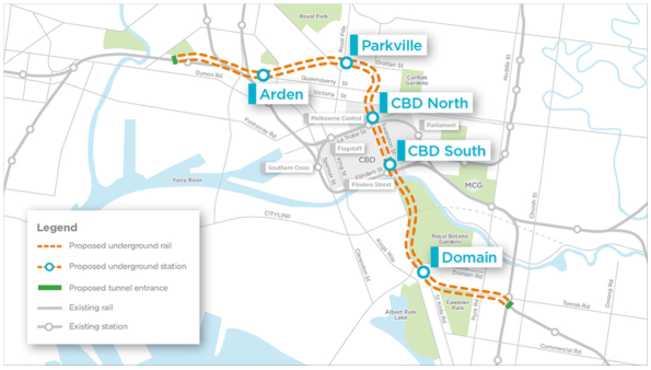 Figure 1 – Metro extension alignment
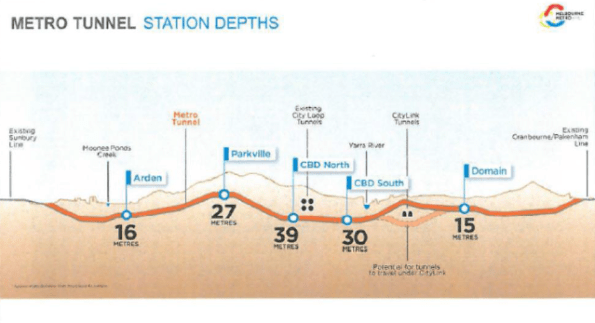 Figure 2 – Metro extension station depths
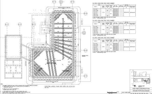 Figure 3 – Typical strut layout
So, into the meat of the issue. I was asked this week to investigate ways in which the installation timeline could be ‘rationalised’ to try and gain some time back on one of the excavations. Feedback given by the team working on site identified that the critical path for the installation of the waler and strut at each level was aligned to the amount of time the resin, for the bolts holding the waler support bracket, took to cure before loading (Min tcure). On the design drawings (figure 4) supplied by Yongnam, the detail stated that the epoxy adhesive should be Hilti HIT-RE500 or equivalent. As detailed on figure 4, this instruction is the same detail for each of the levels of struts, even though the waler and strut size at levels S6-S8 is much larger than the upper levels. The selection of the resin is based on the calculated shear and tension at the bracket location. The installation team suggested that this is most likely a standard detail on the upper levels, basically, to meet design timelines Yongnam will have designed for worst case shear and tension and then applied this across all levels. In terms of time, the minimum curing time for HIT RE-500 is 16hrs, which means the installation process is split across multiple 8 hr construction shifts. Whereas, for lower calculated shears and tensions, HILTI have other products such as HIT-HYH 200-R which cuts the tcure down to 2.5hrs, enabling more construction to take place within the 8hr shift and speeding up the overall installation process. There is also a combination of bolt size and resin selection that can be achieved to optimise tcure for each level of struts, dependent on the calculated shear and tension.
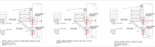 Figure 4 – Waler bracket detail
The RFI has been sent back to Yongnam to confirm the shear and tension at each plate location, so we can rationalise the selection of the bolt and the resin selection at each strut level. This detailing is something that I had never really considered could have such an impact on a project timeline, especially such a big influence on the critical path. This may be of some use to other phase 2’ers being asked to rationalise their own construction timelines. I will update the blog in the comments when I get the feedback from Yongnam and the final calculation of time saved is completed. Thoughts welcome on any other tips and tricks for cutting this time down?

Glynn
Nice blog…I know more about the job you’re on that revealed in AER1!
I had difficulty actually seeing the dimensions involved
But I not the trip plate girder waler at the lower levels – I last saw something like this after a cock-up on the Crossrail project.
The prop spacing appears to be 4m? There is lots of mileage in trying to understand the support system density.
Anyway I guessed the bracket spacing to be the same as the prop spacing and used the heavy 3 waler loading and made a guess at the bracket dimensions, assumed temperatures, low concrete grade (since its piles) and put the lot into Hilti Profis and I get a low utilisation using HIT RE-500 and max’d at 25% with HIT-HYH 200-R
Then I used a mechanical anchor HST3 and get similar results
So:
a) why are the walers so heavy anyway?
b) what is the bracket spacing ( clearly the lower the less the actions to be dealt with
c) since there is no curing time on mechanical anchors – why not these?
It’s me again
I was thinking about this problem during the drive to the office
The first thing that occurred to me is that I have underestimated the waling vertical load to the support bracket…errr by a factor of 10!
My guess ( with a bracket spacing @ 4m is a support action of something north of 250kN
So…….hold the clac given above
However looking at the real killer ; it is probably the combination of tension sand shear in the connection to be taken through the anchors. So looking at geometric ‘outs’
a) spacing of the brackets reduces the per bracket action
b) the vertical spacing of the wall connection points – increases the moment lever arm and reduces the per (upper) leg tension
But I still have the niggling feeling that you won’t get more out of a resin fix than mechanical .
If the issue is the resin set time then ………..
So watch this space I’ll check the fixings again
Interesting read, ironically same gut reaction this side of the office before we even discussed it. Mechanical anchors, longer lever arm if your at the edge of capacity, and finally, if you’ve got the ability to fix to the side of a pile rather than face fix you avoid tension and end up in shear again at the top fixing, which is a winner. Last option does require contiguous piles or braking out. I’ll watch with interest.
Right- rechecked at the higher loads (x10!) and can get M24 mechanical anchors to work(just) and a range of resin anchors – some at M16
On large diaphragm wall jobs it is not unusual to include breakouts from the embedded reinforcement cages so the reapplication of fixing is avoided
Might have done the same on the secant pile cages
Thanks for the replies. I have asked the question to the PE about the use of mechanical anchors, however, John I think from your last response that M24 anchors bolts just managing to work will explain the reason why the resin anchors have been selected? Although, the range of resin anchors does sound like there is a possibility to reduce the tcure and enable a reduction in the installation time. I will have a look at calculating the loads myself and see if I can come up with a solution whilst I wait for the RFI to be answered by Yongnam. To add some more detail; A soldier pile wall with shotcrete infill (piles at 1.5m c/c), maximum bracket spacing is approx. 5.5m, triple waler size is 3UB 1016x406x748kg/m and double waler size 2UB1016x406x883kg/m.
To try to answer the other questions you raised regarding the density of the strut system, this is my current understanding of the factors;
a) The excavations are into the Melbourne Formation, a rock stratum of heavily weathered to unweathered siltstone and sandstone, which has several joint sets effecting the loading on excavations. In the case of this shaft, the joint sets exert highest load on strut levels S6 – S8, position of the triple waler.
b) Masonry heritage structures and high-rise structures near the edge of the excavation resulting in very small tolerances for allowable wall deformation and allowable settlements, therefore a very stiff system of struts and walers is required.
c) Redundancy in design of One Strut Failure (OSF) requiring a large size waler to be able to safely re-distribute load in this case. The inclusion of forks into the design reduces the effective length in the failure case, but these are not on every strut.
d) Project timeline requirement to concurrently excavate adit during shaft excavation which decides on the layout of the strut system in elevation. Ground anchors replace struts at lower levels.
I have tried to add more drawings to this comment, but don’t seem to be having any luck.
Glynn,
I have recently been involved in a resin vs. mechanical anchors design debate.
Our issues were related to fire resistance and cost of fixing steel end plates to r/c walls.
Originally specified resin anchors were deemed to fail in 60 min fire rating. The epoxy would lose its bond strength and allow pull out in tension. Mechanical anchors appeared to solve this but at double the price!
Money talks and so our structural design engineer was told to make the resin option work. His justification for a return to resin was that the r/c walls would provide lateral restraint and therefore remove the need of the connection to resist tension. So long as the bolts had adequate embedment, they only needed to resist shear.
Pass, tick, OK.
From what I’ve learnt, resin is a bit more fiddly and requires greater QA/QM but cheaper. Mechanical is fast and simple but you pay a big premium.