How to Splice up your life?
Just a quick post to see if anyone has a solution to the following issue which has arisen on my site, thought not in my immediate team.
BLUF: As I briefly mentioned in a previous post in order to avoid excessive wear on the TBM cutting head the designers have specified Glass Fibre Reinforced Plastic (GRP) reinforcement bars in the piles making up the head wall, through which the Tunnel Boring Machine (TBM) will eventually punch a hole. These have finally arrived following a series of delays but now there is some uncertainty on how the bars will be spliced together, as the team want to avoid the use of steel couplers.
Below is a picture of the GRP bar and the initially proposed method of using steel couplers;


My initial thoughts are that while I understand the use of GRP bars to avoid cutting through masses of steel I am surprised that relatively small gauge steel couplers will have much effect on the cutting head of a behemoth 15m dia TBM? Surely a monster of this size will just tear through the GRP bar and spit the couplers out whole at the other end?
If the couplers are likely to have a detrimental impact on the cutting teeth, then what might be a viable solution to forming a credible bond between sections of cage?
I welcome people thoughts and solutions.
UPDATE – 16/07/18
I don’t think my original description of the issue was very clear and what looks like a threaded end on the GRP bar in fig 2 might have been misleading. The bars were always going to be lapped (fig 1), but with U-bolts as seen below holding them together (I incorrectly called them couplers in the original post).
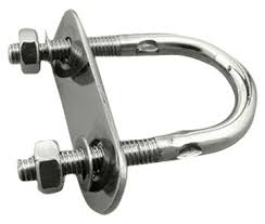
fig. 3 – U-bolt
Although these appear quite insignificant, the TBM guys have said they don’t want any steel, including these, in the piles when they cut through the head wall.
A number of possible solutions were investigated including cable ties as was suggested by Jim in the comments. However, these were deemed insufficient as the lapped connections will need to support the weight of a lower cage during installation.
Each cage is made up of two cages of around 15m in length. in the worst case loading the weight of the lower cage, 1200Kg is supported over 4 spliced connections as shown in the fig 4 below;

fig 4 – cage cross section
The solution that was put forward and adopted was to drill and fix 7 GRP pins through both GRP bars at each of the splice locations as outlined in fig 5.
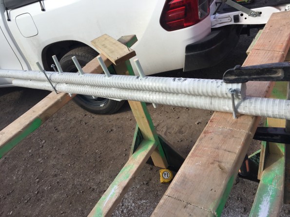
fig 5 – proposed solution
In order to adopt this as a solution, the connection had to put forward for testing to check that the strength of the connection was sufficient. The test load was based on the following;
- 1200Kg/4 splices -> 300kg per splice -> design load = 3000N
- Load test to 3000N and hold for 5 min
- Load test to 7500N (2.5 x design load) and hold for 5 min
- load test splice to failure (hopefully achieving 5 x design load, 15000N)
the image below shows the testing rig that was adopted by the lab;
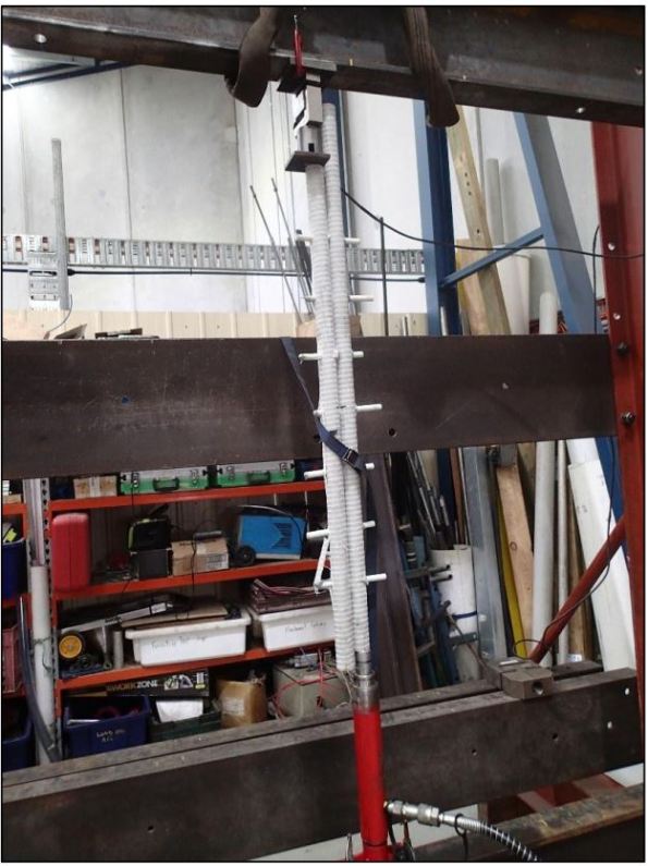
The test was repeated three time on the test pieces and yielded positive results with each test reaching 1500Kg with no defects, defections or cracking observed. This has now been adopted as the preferred solution.

How about using zip lock plasti cuffs /electrical tie wraps / plastic handcuffs or whatever they are called these days?
Hi Jim, I believe that is actually one of the options that was considered. Given the nature of the connection and the requirement to support the weight of a lower section of cage I don’t think the zip locks provided a strong enough bond between the bars to prevent slipping at the connections.
I have heard of the provision of soft piles or soft panels in diaphragm walling and never really though about it much
There is a question as to what the reinforcement is doing; There will be some BM and shear forces in the wall panel and I assume that, as the tunnelling proceeds the local lateral pressure on the panel is removed so that these go down around the tunnelled area
So the soft panels ave to stand for a while before the TBM is introduced
My first thought is how long does it take the lateral load to come onto the panel?
There is lots of research on this. On searching you may find ‘Behaviour during construction of a cantilever diaphragm wall in stiff clay at Limehouse Link’ Moran and Laimbeer
yes for tis I! We measured very low flexural strain in out fully instrumented wall panels . Even close to dredge in a cantiliver of 32m length and dredged to 14m depth. It took 2 months for the loads to come on ( this is stiff cly and the stiffer the material behind the wall the longer it will take for loads to come on
I suppose what I am implying is that you probably don’t need reinforcement in the short term
Remember concrete has a flexural strength of about one tenth of its compressive strength. Structural engineering choose to ignore this
So back to the question . I don’t quite know where it comes from by generally a 40 dia lap permits the axial stress to be transmitted between tension bars – so ignore the couplers and lap…Jim’s garden shed idea may not be so bonkers after all
John, I haven’t yet been able to find the design loading specifically for the short term headwall case, which might suggest it has been reinforced to deal with the same loading experienced by the sidewalls in the long term case? (i.e not taking into account that the TBMs will remove a huge loading area when they burst through)
Also I think the time frame from when the load starts going on as we excavate and the when the TBM has actually been assembled in the portal cuts through will be probably be at least 4 months.
The ground profile to the base of the excavation is roughly 7m mix of clays and silts, followed by 7m of Older volcanics residual soils (described as stiff to very stiff clay), then 4m of basalt, so in the short term (whatever that is) we might have been ok, but I think given the time involved the load will have time to develop.
In terms of splicing the GRP, the issue is the strength of the connection while lifting the cages into the bored hole as the cage is made up of 2 parts and the bottom half weighs 1200Kg which will need to be supported by four bars. The 2nd photo in the post is misleading as it shows a threaded end to the bar. The plan was always to lap the bars, but the TBM guys have said the steel U clips (not sure of the proper name), see 1st photo, are a no go. Those are the clips I thought a TBM would just spit out whole.
I am just pulling together the info on the solution that the team have decided on and I will add it to this post once I have it.
Hi Augustin my thoughts would be to go for a propitiatory system from the manufacture for the couplers if one exists? I assume it doesn’t though or you wouldn’t have asked about it.
Without any experience of this type of reinforcement at all I would be hesitant to use metal couplers designed for ‘normal’ rebar. The couplers I have on my site have small threads on the inside which accept the threads from the re bar you are joining. This connection is therefore relying on the shear strength of the steel along the length of coupler for propitiatory systems this is no problem as they have been designed to work together. By mixing GFRP Bar with steel I would suspect the thread size might vary slightly or the shear strength of one is less than the other therefore failure may occur much lower than expected.
If it was me I think I would be looking to simply lap the bars ensuring the full development length was achieved. You would end up using more rebar but I think the risk you would be taking, by forcing two systems that were never intended to work together to do so, would be significantly lower.
I had a quick Google and came up with this http://www.aslanfrp.com/resources/Aslan-100-GFRP-Rebar-brochure.pdf. The company do talk about the exact thing you have stated your using it for i.e. a ‘soft’ wall for a TBM to punch though. There might be some value in just calling them and having a conversation.
Hope that helps.
Ben
Hey Ben,
the first picture with thread at the end of the bar might have thrown you off a bit, the plan was always to lap the bars. The issue is with the method of connecting the lapped bars as the TBM guys have said we can’t use steel U couplers (I might be using the wrong name) see the second photo.
I note the link you sent talks talks about using nylon zip ties or plastic bar clips. I’ll explain where the team are going with the solution shortly.
I’m not sure if you get a notification or not, but i updated the post with the adopted solution
Not sure why I didn’t get a blog post notification for this one at all; if it happens again I’ll look into it. I’m with you on the “what’s the problem?” front, surely if you can cut through basalt a small white metal coupler is peanuts. If that really is a problem then I’m with Jim on the cable-ties, which I suspect would generate sufficient bar to bar friction to hold the anticipated lifting loads and then keep all in place to allow for lap length (40D as JM says from BS 8110 now adjusted in EC 2 but generally not much different if not at full working stress). I suspect that a quicker and equally effective solution to the drill and dowel one adopted could have been provided with a rapid setting epoxy glue between the bars over the lap length (gaffer tape might also have worked but would be an issue with transfer of forces in the lap). Was there any reason why normal tie wire connections cannot be maintained throughout? Why can’t the bar be provided in 15m lengths or greater?
Hi Auggy,
A useful update, we are looking at using GRP bar for the tunnel connections. From a H&S point of view; are there any identified risks when the team are removing the U-bolts from the cage after it has been lifted to the vertical position? Also, if the cage has to be removed in an emergency during installation, how does this system provide stability once the U-bolts are off? I understand it is good in pure tension, but I can’t quite understand how it would deal with bending; are the pins fixed?
I don’t believe there are any additional risks that aren’t already covered in the contractors safe working method statements (SWMS). They are already working around the cage as it is being lowered in to remove the rigging equipment.
If the cage had to be removed in an emergency it would have to be lifted vertically to avoid stressing the pins in a way they haven’t been tested (or put U-bolts on on the way out if time permits). The pins are epoxied in but U-bolts stay on until the cage is vertical and being lowered in.
Of note the lifting plan for the cages was amended to include an additional lifting poor for the GRP ones because of the significant sag. (4 lifting points for steel cages, 5 for GRP)
Do you happen to have the material properties for the GRP bars?