Home
> Uncategorized > Seismic Assessment of a Structure – Fundamentals (Direct Displacement Based Design)
Seismic Assessment of a Structure – Fundamentals (Direct Displacement Based Design)
Introduction:
- I’m trying to get my head around some seismic design for the building I’m working on. I’ve done a bit of reading – here is a quick description of my understanding so far, anybody else done any seismic and can collaborate? Any thoughts or corrections?
Assumption:
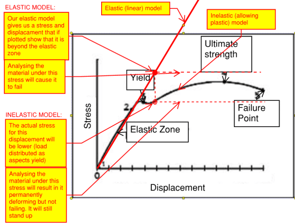
- EQUAL DISPLACEMENT RULE. (total displacement of an element is roughly the same whether you treat it as fully elastic or non-linear) – proven empirically but the theory is that energy is dissipated when a material yields and therefore the demand on the element is reduced.
Graph:
 Process:
Elastic Model (or elastic calcs) – FORCE BASED DESIGN (what we are used to):
- Input: Apply seismic loading
- Output: Displacements and stresses
- Compare displacements to SLS criteria (eg inter storey drift max = 0.015 x storey height)
- Check materials can withstand the stresses (in the example in the graph, it will fail)
- However the results may not be truthful to how the material/structure will actually behave – you may be in the plastic zone and as a result, overestimating the stress in the material. There are factors you can apply to bring the stress down but a more accurate approach is to use DIRECT DISPLACEMENT BASED DESIGN
Inelastic model (or non-linear calc iterations) – DISPLACEMENT BASED DESIGN:
- Input: Displacement – input the displacement our elastic model gave us (equal displacement rule). (if you are designing a new build then set your target displacement and start here). The target displacement is then sub divided to create start and end points for each stage of analysis.
- Iterations must be conducted in order to find the critical mode of deformation.
- Output: Stresses
- Check materials can withstand the stresses (in the example above, it will now pass (permanent damage but no collapse))
Other:
- When setting up the model, applying high levels of fixity at connections is conservative (the opposite to what I think is intuitive) because:
Summary:
- Force based design does not allow an accurate estimation of stresses within a structure for material that is beyond yield. Direct displacement based design allows for a more accurate estimate because displacements are more proportional to non-linear behaviour/energy dissipation?
Categories: Uncategorized

Nice, Load goes to stiffness but if you form a hinge then redistribution occurs (you will recall a concrete framed office block example). If you are going to exceed yield then yield line analysis for slabs and something a little simpler for frames is one way forward.
Don’t really understand displacement method
I assume you permit a ‘code allowable’ displacement and work backwards to the forces within the displaced frame?
But I believe this will give structural requirements of (particularly the connections in) the frame will be rididulous
This is because if you try to keep the frame in the elastic range under these displacements the whole structure would be way over designed
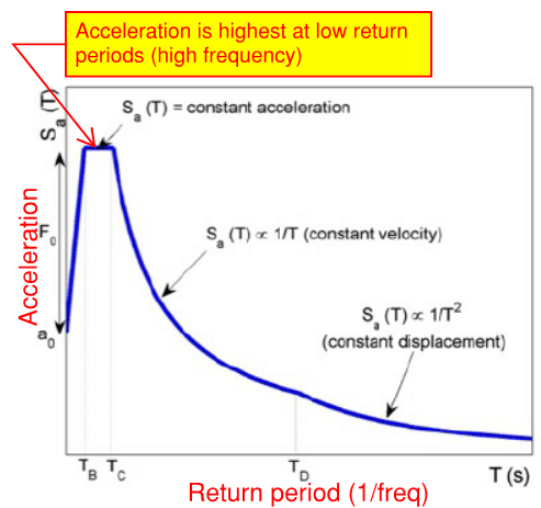
We think of a seismic event not as a direct loading but an inertial loading. This is because the ground acceleration is very rapid and the building has to ‘catch up’. Since the superstructure has mass the catch up acceleration gives the ‘equivalent’ applied force ( this is the basis of the equivalent lateral load method
The force implied by the impalement is the work done (the energy input)
This energy has to be dissipated before getting to the structure and/or absorbed by the structure
The reason an elastic design will not practically work is in your graphs. The energy absorbed is the area under the stress-strain curve
If structure components can be designed to yield then the stresses are kept on your BLACK line the energy (per unit volume) is the area under the curve so instead of going up the RED line.
However this demands the ability in the frame to go plastic and this is a particulr issue at the joints. Here’s a £million quid idea…. use stainless steel joints in a steel frames structure- why?