Drainage tanks in slopes
My latest Ph3 task is to coordinate the design of a reinforced slope with a surface water attenuation tank buried inside the embankment. Every part of my engineering judgement makes me think this is a bad idea – the challenge is to now engineer a solution that will work.
Background
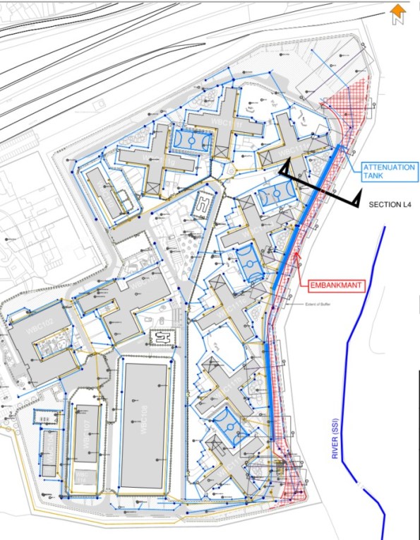
The site lies on hill adjacent to SSI (a river and marshland). Two major risks with the sloping site;
- Excessive surface water run-off.
All surface water drainage requires attenuation to limit the discharge into the river. The redevelopment work will increase the capacity and size of the facility by 4-times the original.
- Major cut and fill exercise.
Project design specifies split levels and requires major cut and fill exercise to create plateaus for several large buildings.
Initial Design
Initial storm drainage design located attenuation tanks under sports pitches. This is an ideal scheme; large areas with minimal loading permits shallow excavations for large capacity tanks.
The Construction Phase Plan could not be achieved in unison with this scheme. Large laydown areas were required to facilitate the erection of multiple pre-cast concrete buildings simultaneously. Freedom of movement for heavy crawler cranes was integral to critical path activity. Any buried attenuation tanks would not have been able to handle these loads and the scale of temporary works to mitigate damage was not cost effective.
A large (350m-long, 6.0m high) retaining structure is necessary along the Eastern edge of the site to achieve level ground. Initial design concepts sought to utilise excavated Oadby Till (Clay) to produce a cement stabilised embankment.
Issues
Boundaries – Need to move the location of the attenuation tanks. The only available space where the tank could be buried deep enough to handle heavy construction traffic was adjacent to embankment.
Properties – Contractor is keen to use materials won on site to reduce costs (and claim some sustainability benefit). The clay alone does not have the capacity to achieve the 40-degree slope required. Confirmation of material strength following cement stabilisation can take 35+ days. This would not work with an already compressed programme.
Ground Water – A second design to reinforce the clay has been proposed but in an undrained state, the tails of geogrid would clash with the only available location of the tank.
Contamination – An underlying mudstone layer has high sulphate levels that are detrimental to cement stabilisation. Some of the boundary layers are ill-defined and risk of sulphates with the clay exists – further justification to reject cement stabilisation.
Options
My role is to understand if the following concept is achievable;
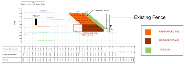
Major demolition works on site have generated a source of granular fill. This screened 6F2 could be used to form a steeper embankment and prevent a geogrid/tank clash due its superior characteristics. Preliminary calculations suggest there is insufficient quantity of this on site to form the entire embankment.
A hybrid embankment could be the solution.
Using drained granular fill to support the lower section of the embankment means shorter geogrid tails can be used next to the tank. The cut and fill clay will form the upper section of the embankment where the geogrid tails can extend above the tank. This maximises the re-use of material won on site.
I know others have looked at earth embankments – any thoughts?

Hi mate, just looking at your site plan the majority of the surface area of the site appears to be buildings (roof space). Is there a solution in attenuating more of this run-off in smaller tanks near the buildings or re-use as grey water within the buildings rather than one large tank in the embankment? I’ve probably missed something, but could be an option.
A nice thought but every inch of space is used up by plant and services. Can’t talk about the details of the project but needless to say, the ‘residents’ need to be kept away from anything live…
The slope design is actually panning out OK. I’m currently trying to place vertical obstructions (manholes) through layers of geogrid. Taken a bit of finding but essentially you splice it in a similar fashion to re-bar detailing around a void in a concrete slab.
Trying to work out if movement in the slope will induce lateral loading on these manhole shafts when the splice geogrid goes into tension.
I have previously used a device called a ‘Garastore’ to attenuate individual property storm water beneath garage floor slabs. I appreciate your residents will not have the freedom to keep a vehicle in any of the wings so no garages, but there might be an underfloor storage solution to be found depending upon the proposed construction details. This can also lend itself to rainwater harvesting, which can be a simple pumped solution to a pressurized untreated supply main.
Recognising your role as being proof of concept not redesign I would suggest that, if the attenuation tank as shown is a fully sealed affair with inlets and outlets, there is no reason why it should not exist in the location shown without introducing water into the soil where it is not wanted. The only question I would have is with regard to the existing design hydrological regime i.e. where’s the ground water and what effect might this have on the tank and vice versa. Will flow be affected/diverted and/or is buoyancy of an empty tank an issue?
Do update with the eventual solution.