Unexpected Depth
I’m currently the Project Engineer overseeing the construction of 2 large pile caps (2 of many pile caps across my scope) for the main bridge crossing the Maribyrnong River in Melbourne, part of the West Gate Tunnel Project. We are aiming to start pile cap construction on completion of piling.
We had an interesting pile refusal I thought I’d share and get some feedback on?
Given the size of these particular pile caps, it should provide a unique experience into the construction process and QA. To give an idea of the pile cap sizes and loads being transferred from superstructure into the ground, each pile cap consists 46 precast piles, each 34m length. Due to the length of these piles, each pile is made of 3 segments, spliced in two places. The bottom segment is 10m long with the middle and upper sections 12m long. Each pile cap will consist 370m3 of concrete (16.6m x 7.2m x 3m deep), 108T of reo and will have post tension bars protruding out the pile cap and up into the precast column – a feat in itself to ensure correct lengths were procured with threads considering elongation lengths (3-6 month lead time required due to fabrication in South Africa) and potential clashing with pile cap reo; we are currently conducting 3D modelling to detect any clashes.
During piling this week, everything was going well until a single pile refused well above the expected depth – piles are driven to a layer of basalt rock approx. 32m deep and are considered end bearing. Each pile is designed to take a geotechnical design load of 2900kN, which is very high for a precast pile. The pile in question can be seen below. The variability of the basalt rock layer can be clearly seen.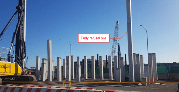
e believe the pile has refused on ‘floating basalt’ (i.e. a large basalt boulder in the upper silt layers). Because it has refused on the basalt, it has the required ultimate geotechnical capacity of 3867kN (note this is the 2900kN with a reduction factor applied – a different approached used under Australian Standards from that used in EC7).
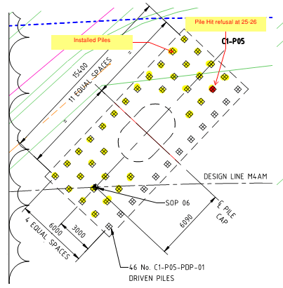
Pile cap Plan
We can’t just crop the pile at the current depth for a couple of reasons. Firstly, the top splice joint is 0.5m below pile cut off. Under VicRoads 605 (Driven Piles) publications, a minimum depth of 5m is required for splices, due to durability (a blanket requirement that doesn’t seem to consider soil properties at individual sites?). Also, I believe this depth ensures bending moments, which are increased near the top of the pile, are not too excessive at spliced joints.
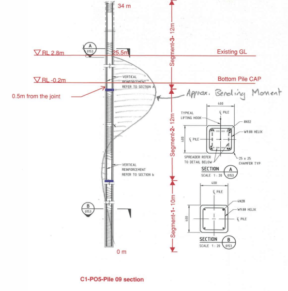
Refusal Depth and Estimated Bending Moment
The other issue is that the steel reo in the middle section pile is not sufficient structurally to transfer load from the pile cap to the pile (top segments have almost twice the reo).
As the pile has reached geotechnical capacity, I believe a replacement pile need only be required to add additional structural support (i.e. shear and bending capacity) – i.e. install a top segment pile as a floating pile next to the refused pile, providing the structural capacity required without carrying any geotechnical load.
However, the decision was taken to install a longer pile (matching the refusal depth) using segments with adequate reo. This, to me, seems slightly more conservative given geotechnical capacity was proved? Either way, the importance of getting a decision signed off quickly was paramount to allow piling to continue and keep on schedule – a decision was made within 24 hours.
I’ll upload a blog once these pile cap begins construction!

So, for the overturning actions the piles in a ‘rivet group’ ae all designed at the same length and that would be the length required for the put piles.
The bending moments induced by the lateral actions being applied at a height above the cap are normally taken in the upper horizons
SO these are in your favour
In the geology you have the issue of early refusal ( on an erratic) was pretty likely so I wonder if the groups had been slightly overdesigned with that risk in mind?
Hi John.
It seems early refusal was likely, but I think the depth in this particular case was not considered very likely, given a borehole was taken in the centre of the pile cap and did not encounter any floating basalt. Either way, variability of the basalt on both the east and west banks of the river has been incredibly profound and frustrating for the contractor – also causing issues for our programme having to wait for RFI/NCR responses.
Given the piles are taking very high loads of of 2900kN (or 3867kN geotechnical design strength after the application of the 0.75 reduction factor) I’m not sure how much risk allowance can be designed into these? That being said, there are a very high number of piles, so maybe the designers have allowed for this risk by upping quantity. They were very keen to ensure a pile be inserted next to the early refusal though.
We are restriking the piles tomorrow so will be able to establish competency of the pile group.
Having read the title in a hurry as “Unexpected Death” this was a little less exciting than I had hoped for! I recall Joe Woods having a similar issue with pie refusal, in his case it turned out the upper layers were made ground and they had hit a piece of old concrete jetty that was in a previous dip at about 8m below the surface. The proximity of other piles all driven to depth makes this appear to be quite a small diameter piece of floating basalt. I look forward to further instalments…
Dan, given your BM diagram – are your piles re-inforced all the way down (along)? The CFA piles we are using on my site are only re-enforced for the upper section (makes sense given where the BMs are) but if you have re-enforcement throughout I can only assume then that this must be due to the driving methodology?
Ash, you are correct in a way. Reinforcement design for bending in the permanent state and for driving are not the only requirements. Bending of the piles during pitching has to be considered too, hence the reo throughout the whole pile – clearly not an issue you have for CFA piles. Bending reo for driving, I think, is not so much a concern as the other two. The concern here is more for shear forces at the pile toe (a shoe has been provided for this) and the pile head from driving forces associated with the hammer impacts.