Design Risk? Perhaps think twice or double-check…
I’ve delayed sharing this post as I was waiting for the completion of the investigation report however it looks like it will continue for some time. The information in blue italic text is taken from the draft incident report summary prepared by the safety team on site. I’ve also interspersed comments and pictures to aid understanding. This incident is a sharp reminder of design responsibility as we look to transition onto Phase 3 next month. At the heart of the incident is the combination of 5 issues:
- Incorrect design/design shortcuts
- “I’ve done this before/This is how we did it last time”
- Short notice change of plan on site
- Lack of communication between the site team
- The interface between unplanned or different activities on site
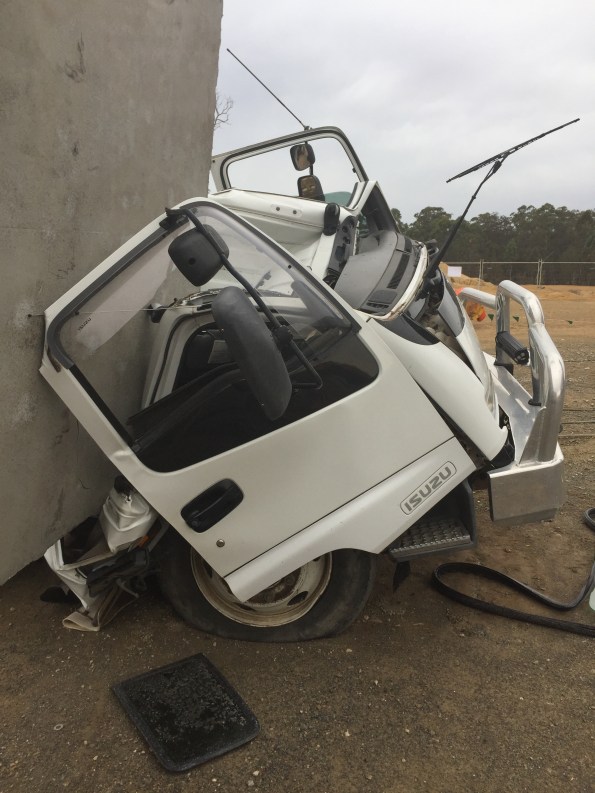
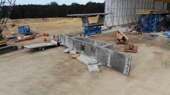
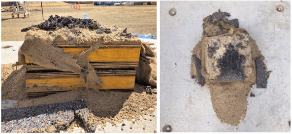
First, a few pictures to whet your appetite to read further…


Now the pictures have got your attention I thought I would share a little bit about the serious incident that happened at the pre-cast yard in September. The incident was classified as a 1P incident under the John Holland system. 1 = most serious (deadly consequence) P = potential (fortunately there were no injuries). The incident cost is valued at A$ 100,000
Executive Summary
John Holland has been engaged by Roads and Maritime Services (RMS) to construct a new bridge on the A1 Princes Highway over the Clyde River at Batemans Bay. The new bridge will improve access to Batemans Bay and surrounding areas, allow access for larger trucks, reduce traffic delays and improve the Kings and Princes Highways intersection
The project involves the upgrade of approximately 1.55km of Princes Highway between North Street and Kings Highway from predominantly two lanes to four lanes, two lanes in each direction. It includes a new 420m long bridge over the Clyde River, located to the north-west of the existing bridge. The bridge consists of a total of 168 segments currently being manufactured at the projects temporary precast facility located approximately six kilometres south of Mogo.
At 09:00 on Friday 20th, September 2019 a 250-tonne crawler crane lifted Segment P5-1U (the segment) off the transfer table and placed the segment on support pads. The segment weighed 95 – tonnes. The support pad arrangement consisted of three support points, two on one side and one on the opposite side, the pad on the single support point taking fifty percent of the load.
A section of the support pad arrangement is shown below: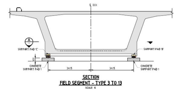
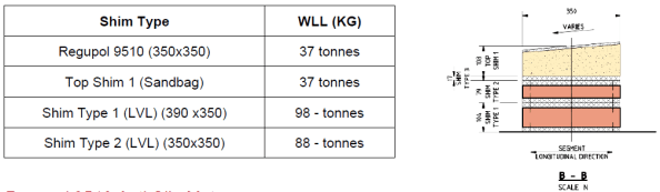
The support pads consisted of a concrete pad with a specified shim arrangement on top; the shims consisted of an anti-slip rubber mat, sandbag, and timber shims made from TRU Form and LVL plywood. Each segment had a specific support pad shim arrangement to suit the segment profile detailed in the Temporary Works 23 design package (TW23).
An example of the shim arrangement is shown below. The WLL table was produced as part of the post-incident analysis and was not available on-site prior to the incident.
Segment P5-1U was one of the larger segments cast to date and as a result, was to be utilised during the Straddle Carrier Crane Safe load test scheduled for Tuesday 26th September. The Straddle Carrier WLL was 110 tonnes. The Crane Safe certification test required a test load of 110% (121 tonnes).
On Saturday 21st September, the Precast Manager instructed the crane crew to place concrete pads next to the segment in preparation for the load test. Later the crew were instructed to load four concrete pads onto the Segment. Between 10:00 – 12:00 four concrete blocks, each weighing 2.2 tonnes, were placed by the crawler crane in predetermined locations on top of the segment to achieve the required weight for the Safe load test.
The following table shows how support pad B was overloaded by 28.4% prior to adding the concrete blocks and 40.3% after adding the blocks.

At approximately 12.30 a truck arrived from the main bridge site, returning a spreader beam. The truck driver was instructed by a rigger to park within the radius of the nearby crawler crane. The crane crew unloaded the spreader beam; the truck driver then proceeded to prepare his truck for departure.
I highlight the interface between concurrent activities on site which contributed to the severity of the incident.
At approximately 12.55, almost 28 hours after placing the segment, the truck driver was standing at the back of his truck and heard a noise. Upon looking up, he saw the segment moving at which point he quickly moved further away from the back of the truck. The segment then fell over, landing on the cab of the truck and concrete pads.
The truck driver had just tightened his last truck ratchet strap and was about to get back into the cab of his truck.
The following picture shows the failed shim. The grey/black material is the Regupol mat.
The Precast Manager immediately attended the incident scene and, having determined no one was injured, secured the area and ceased all works in the precast yard, and made the required notifications.
Key findings:
• The WLL of the anti-slip rubber mat was not checked during design
The design had been used previously on another project in Sydney however the segments on that project had a maximum weight of 70 tonnes.
• There was no technical specification for the sandbag in the design
• The WLL of the anti-slip rubber mat was exceeded by 10.5 tonnes (28.4%) prior to the placement of the concrete blocks (8.8 tonnes) and by 14.9 tonnes (40%) when the additional 8.8 tonnes was added for the Straddle Carrier Safe load test
The issue of the inadequate design was exasperated by a site change to the load test procedure.
• The TW 23 design package was assessed as Low Risk, requiring no independent design certification. Had the risk been rated as “significant” (i.e. by way of Catastrophic consequence and Unlikely frequency, independent design certification would have been required.
• Support Pad inspection on P5-U identified there was not full contact between the various shim layers and the segment. Thus load transfer may not have been evenly distributed across the surface and may have resulted in potential point loading. This may have placed further stress on the anti-slip rubber mats
• The support pad design was not reviewed following initial issues observed with the sandbags during the placement of the segment P5-U
However it was discussed with the Engineers, Precast Manager and TWC.
• Support pad failure was not identified as a risk when planning the Safe load test, therefore no exclusion zone established around the segment.
Hence the truck was directed to park within the crawler crane radius for unloading. This was next to the stored segment.
Actions:
• Establish an exclusion zone around segment P5-U
• Design a temporary support system to secure Segment P5-U, before lifting and reseating on the new temporary support system.
The segment has been quarantined and cannot be used. It will now be crushed for disposal.
• Review Segment Storage Pad (TW23) design and design validation by an independent professional engineer
Works in progress.
• John Holland TEK Team shall conduct a project-wide Temporary Works Audit (3 days)
• Review the Design Management Plan to include the requirements of JH-MPR-DES-003 TEMPORARY WORKS DESIGN AND IMPLEMENTATION
• Review the Temporary Workers Register classifications and ensure design verification and validation is completed in accordance with JH-MPR-DES-003 TEMPORARY WORKS DESIGN AND IMPLEMENTATION
Review and audit of all TW activities and processes conducted by an independent JH team.
• Review [Activity Method Statemet] to include temporary pad installation and segment placement, detail all temporary works design requirements associated with the activity.
• Develop [Task Risk Assessment] specific to the task of pad layout, installation and placement of segments
• Inspection and Test Plan (ITP) check for pad configuration and shim configuration
• Project Wide toolbox discussing the importance of speaking up if you have an issue or concern
• Communicated Change Management requirements to the wider project team
▪ SQE Risk Management
▪ Design Change
▪ Resources (plant, people, equipment)

Interesting and very fortunate for the driver and all associated. I’m intrigued that an applied action probably well within the deign gamma factors lead to a failure. I also worry about sand filled anything used to provide support for more than a very short term temporary situation because I don’t trust wet sand that dries out or damp hessian…
Form the photos it looks like one of the pair of pads that failed not the single one on the opposite side. Was this really a case of applied load exceeded design capacity or more that the item couldn’t take the design loads and it was just an accident waiting to happen?
If I recall, you are match casting so if this segment is now written off there is a need to recall segments in order to case against them. How is this going to work?
Absolutely very glad everyone walked away from this one. I’ve not got access to the design calculations so I have to rely on the tables in the incident report which indicates the regupol mat was overloaded before adding the 8.8t of concrete blocks. I believe the sandbags were selected as the soffit of the segments varies along the bridge and the designer wanted to ensure full contact was made with the supports.
On the aerial photograph the single regupol pad has shredded (shear failure) this is also shown on the close up of the support. The aerial photograph shows the double support pads which have moved off the sandbags but not failed in the same way. My assessment is the sandbag closest to the toppled segment split when the segment overturned due to increased load at that support.
You are correct, we are using the match casting process. The toppled segment was the P5+1 segment – the 1st cantilevered segment from the pier head segment (on the pier 5 bearings). Also the P5+2 segment had been match cast against the P5+1 segment. The casting cells have a fixed bulkhead which is a problem because we cannot cast a new segment with two match cast faces. The current thinking on site is to cast a smaller replacement P5+1 segment using one match cast face and conduct an in-situ stitch against the other segment to overcome the compatibility issues.
Crazy, I’m not convinced there is a need to write off the segment but could well understand concerns so would then reckon recasting 5P+2 as well would be much easier and more cost effective in the long run than messing around with in situ stitching. Lets wait and see!
I think the decision to recast was made on the basis of how difficult it would be to prove to the client that there was no damage to the segment. The client QC requirements and NCR process is already causing difficulties on site over standard works without the challenges of this issue.
We had a incident on my site a month ago that seems to bear striking similarities to this when considering root causes. In short we had a steel splice plate drop 10m from a steel frame member while the main member was being lifted into the frame. Following the investigation the technical failure mechanism was bolt shear failure but the behavioural root causes were identified as:
– A “we’ve done it this way before” attitude applied to a project with much larger forces;
– Failure to address this risk in the temporary works design, and;
– No communication of this risk area through the design process.
Most striking to me was the “we’ve always done it this way” attitude which implies that this same failed practice is in use on other sites just waiting for the same incident to occur. Despite the potential severity of our incident (equivalent of 1P), it falls into the gap between LOLER and RIDDOR* so will not be reported and commercial fears prevent companies sharing their H&S failures.
*Although the incident was while lifting it was not a failure of the lifting equipment (the crane or the slings/chains/shackles), there was no injury and it is not a specified ‘dangerous occurrence’.
Clearly your site has conducted a detailed investigation, as ours did, but have you reported or will you be reporting this to relevant authorities or advertising more widely to industry peers? Perhaps your incident falls into a different category to mine (failure of ground works perhaps??) and there is mandatory reporting? Unless this is the case UK legislation (HSE) doesn’t seem to differentiate between incidents involving a 95t segment vs a 400kg splice plate vs a 50g bolt – a near-miss is a near-miss and unless injury occurs (or you fall into a specific category) there is no mandatory reporting.
Tom,
The incident was reported to senior project alliance (John Holland and VSL) management, to the Client’s representatives as well as externally to Comcare (JH’s workers insurance scheme) and SafeWork NSW (state equivalent of UK HSE). The site was locked down for both Comcare and SafeWork to visit site and conduct their investigations as part of their incident response procedure. There is a requirement to report all significant incidents to Comcare and SafeWork via telephone hotlines and the site is not allowed to disturb the scene of an incident (except for first aid or to make safe) until approval is given by both to do so. Had the incident been fatal or a serious injury occured there would also be a need to report the incident to police and other regulators.
The detailed incident report and analysis was reported to senior management and a one-pager summary is shared across the JH safety network. This alerts all JH Safety Managers to the incident and enables increase awareness of incident risks that could occur on other projects. These trends are then communicated to the workers via pre-start meetings and toolbox talks.
I hope this helps answer your questions?
It does thank you.
I assumed that there would be full internal communication of the event (within JH and project stakeholders) but was really angling for the mandatory reporting to the authorities. Of course there are differences in our recent experiences but, generally speaking, without a specified injury, specified dangerous occurrence, or near-miss involving the public there is no requirement to report to HSE in the UK.
My thoughts would be there should be voluntary sharing of this kind of information between peer contractors, as you say, to increase awareness and prevent similar incidents on other sites.
Tom,
The bodies you are interested in are SCOSS http://www.ukroadsliaisongroup.org/en/UKRLG-and-boards/uk-bridges-board/standing-committee-on-structural-safety-scoss.cfm and CROSS https://www.structural-safety.org/ both of which are concerned with safety issues in structural engineering despite the peculiar hosting address for SCOSS.
There is, however, a recognised issue in engineering, with the notable exception of the offshore industry, in relation to honest reporting of incidents from which all could learn. It is very similar to the military attitude towards reporting unit activities and success.