Archive
Infrastructure Advice
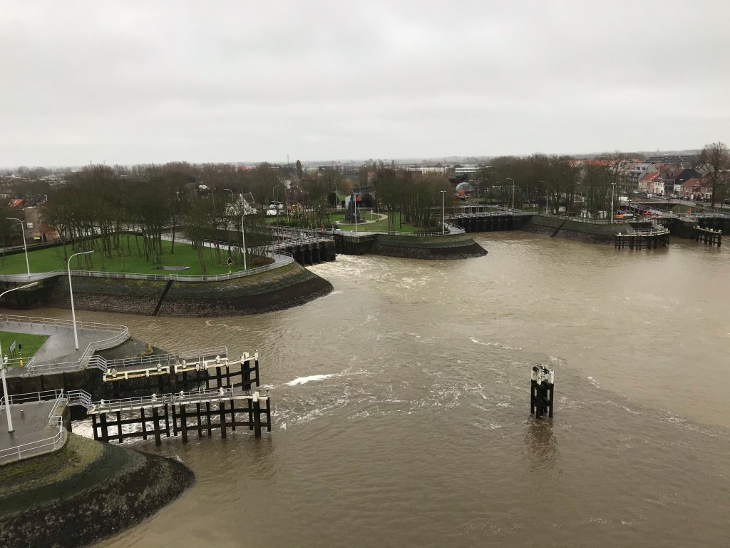
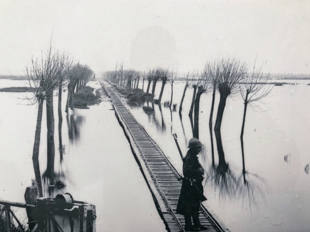
PEW are currently on a WW1 Battlefield Tour, focusing on the area around Ypres. The first stop today was to Nieuweeport, on the Belgian Coast. It was from here that the German advance through Belgium was halted through infrastructure.
The area between Nieuweeport and Ypres is known as the Polder Plain. An area of ground that sits between the sand dunes on the coast and the clay ground around Ypres. In the 17th century the land was artificially drained by the Flemish Engineer Wenceslas Coberghar to enable the land to be farmed. The result is a complex irrigation system which feeds into the River Yser.
During the initial stages of the war, with a Belgium under threat of total German control, King Albert of Belgium made the decision to inundate the Polder plain with sea water. This was done in a controlled fashion over a number of nights. Advice was given by the Belgian engineers who ran the irrigation system; they also oversaw the execution.
The result was that the Germans were halted which assisted the British in the defence of Ypres.
Location, Location, Location!
Location, Location, Location!
I am managing a project which will install additional supports to a flowline on a BP production platform which I think highlights an important factor in pipe design – location of valves.
First a quick bit of background:
Production flowlines connect the surface wellhead with the production equipment, shown in attached image. During well start-up these can suffer “slugging” incidents.
Slug flow can occur due to fluid properties and process conditions (Hydraulic slugging), the system design (Terrain Slugging) or due to a rapid change in pressure (severe slugging). This is a two-phase flow regime characterised by a liquid “slug” followed by a gas bubble (slug and bubble often described as a unit cell).
In hydraulic slugging the flow regime is constant with an associated frequency of slugs with the potential to cause fatigue failure if not correctly designed for; this is like repetitive hydraulic shock/water hammer events. Terrain slugging is a lower frequency slug flow formed by a build-up of liquid in low points of the pipeline with an associated increase in the upstream gas pressure resulting in the held-up liquid forming a slug.
A sever slugging event results from a rapid change in pressure and is the main slugging type seen by production flow lines. From the subsea well the oil and gas is brought to the production platform via a riser pipe which enters the platform through an assembly of valves known as a Christmas Tree. From there the fluid moves through a production flowline to the production equipment.
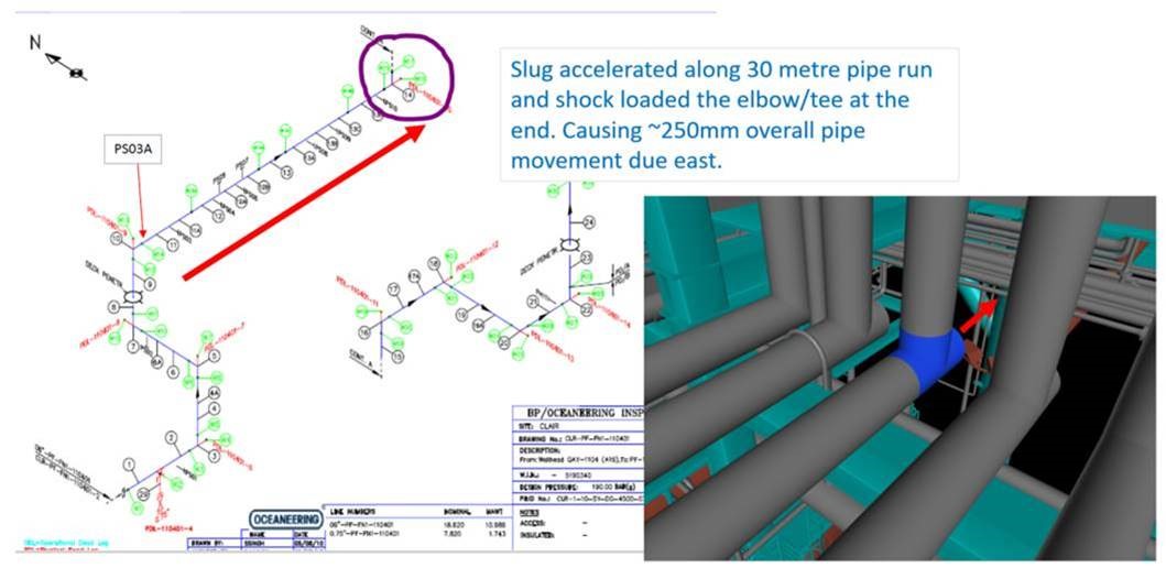
Figure 1. Inspection isometric and 3D model screenshot
The situation:
The pipe run shown in Figure 1 is a production flowline. A choke valve is used to regulate flow and will normally be placed in close proximity to the Christmas tree. On the Clair Phase 1 platform it is at the downstream end of the flowline closer to the production equipment.
When a well is shutdown, gate valves in the Christmas Tree and the choke valve are closed. This traps an inventory of fluid in the production flowline which separates into two separate phases with the gas rising to the top. Similarly, in the riser below the Christmas tree the fluid separates, leaving a gas plug below the Christmas Tree at pressure at a higher pressure, a liquid slug above it and a gas plug above that. On start up the Gate valves are opened, and flow is regulated by the choke valve.
On the system in question the gate valves stick then rapidly open fully, allowing the riser gas plug to accelerate the liquid slug through the flowline. There is a straight, horizontal 30m section of flowline (red arrow in Figure 1), along which the slug can build momentum and subsequently hits the 90-degree bend. This has been found to move the pipe 250mm axially with a potential force of 20 tonnes. If the gate valves didn’t stick and could be opened gradually the effect would be reduced, unfortunately replacing these is not an option.
Now, my first thought was to move the choke and reduce the inventory of fluid between it and the gate valve or replace the gate valve. These options have been rejected in large due to the fact they cannot be completed with the well online and producing oil. This follows, what I see as, the underpinning principle in the oil industry in all projects and decisions: “The Oil Must Flow!”
There is also the issue of the flowline being formed of welded joints throughout its length and so would require hot work to create flanged connections for a new valve. This would need a whole platform production outage to minimise the risk from hot work. The other flowlines on investigation also show movement and so any solution needs to reduce the risk for all.
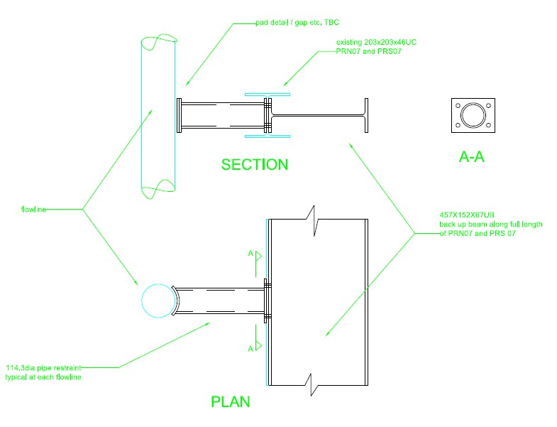
Figure 2. Design for individual pipe supports and required bracing
The solution proposed is to provide bracing to each vertical pipe length, bolted to the web the I beam supporting the horizontal pipe, with an I beam bolted to other side of the web. Additional bracing with then transfer the force through to the main steel work above the pipelines. This set up will provide axial bracing for the flowlines restraining the resultant movement. This was deemed accessible after stress analysis of the pipes showed no areas of concern. Not necessarily elegant but does enable the system to cope with the effects of poor design.
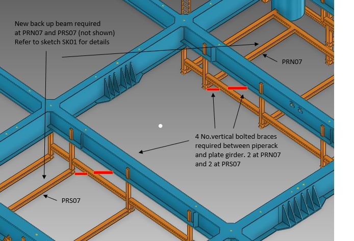
Figure 3. Vertical braces to main steelwork to transfer load
The surprising thing is that this design flaw has appeared on two platforms in the BP North Sea portfolio.
