Archive
Friction connection?
This is interesting. I’m checking a design for a temporary concrete retaining wall. The wall itself is simple enough but the connection is something I haven’t come across.
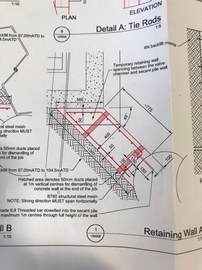
The wall is being held in place with a threaded bar on the right and “friction with the existing wall” on the left. So the designer has said that the angle between the retaining wall and existing wall is enough to restrain the wall. The engineer model I created for it looks like this
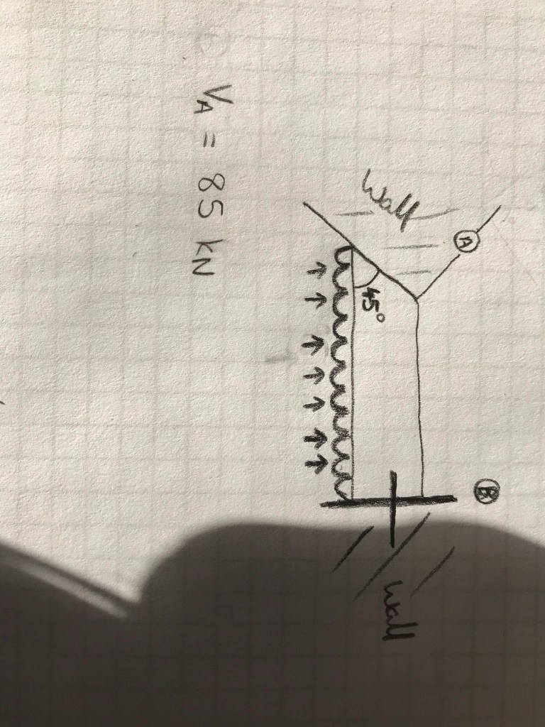
I think as the there is no bond between the two walls that friction alone cannot restrain the 86 kN. I think I should calculate the amount of load that can be taken by the friction (F= u N) away from that end reaction and then treat the B reaction as a reduced cantilever ie increase the shear load in the threaded bar.
Happy for anyone to tell me I’m wrong.
Non-standard Electrical Supplies
I stumbled across an interesting building last week whilst out on a Fire Compliance Survey. Within the Devonport Dockyard, Babcock have a building called the Central Frequency Changing Station (CFCS). This feature is responsible to the provision of “Shore Power” electrical supplies across the dockyard and HMS Drake Naval Base.
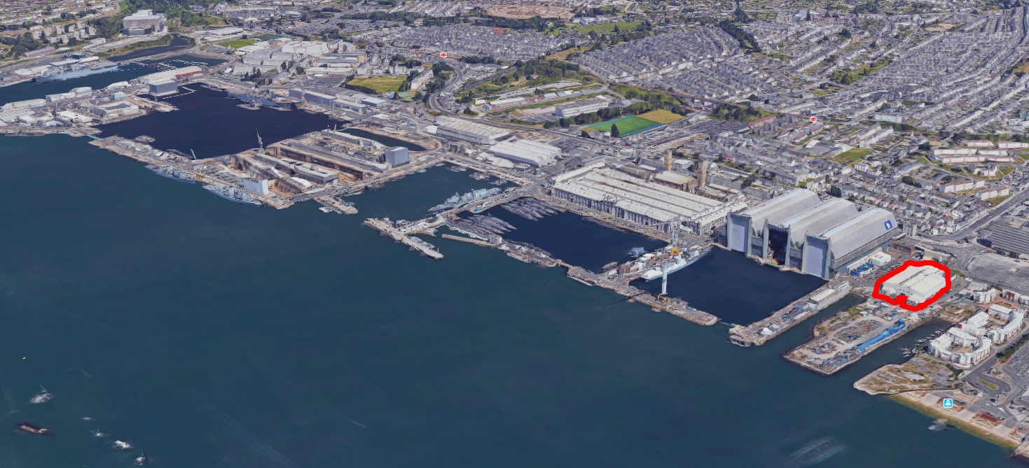
Devonport Dockyard showing CFCS building
Once large ships and subs are docked, there is obviously still a requirement to run auxiliary systems such as HVAC, lighting, battery charging, communications centre, computers and navigation systems. The vessels can provide their own power with their on-board diesel generators, but this results in noise, vibration and emissions as well as driving up running hours and using up vast amounts of fuel. The obvious choice is to just “plug them in” to a “shore supply”.
There is one slight issue; as the vessels make their way from international port to international port; the local power grid supplies can, and do, vary. Most vessels are designed to receive a shore supply of 6600 Volts at a frequency of 60 Hz. “Oh no” I hear the E&Ms cry! Here in the UK we use 50 Hz and generally a HV supply of 11 kV.

World wide electrical frequency standardisation 50 vs 60 Hz
So how do we get around this? Each “Shore Supply” is converted to 6.6kV at 60 Hz by motor-generator units. The CFCS building houses 12 x 10 MVA “common-shaft” synchronous-motor frequency converters.
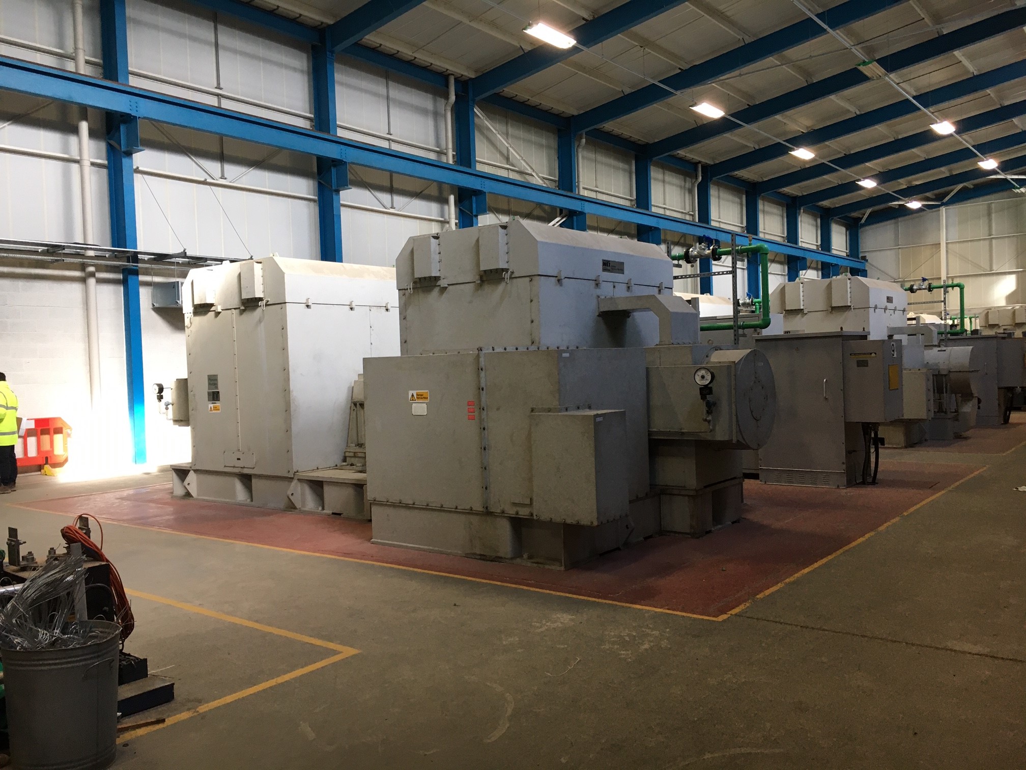
Rotary “Common-shaft” Frequency Converter Units
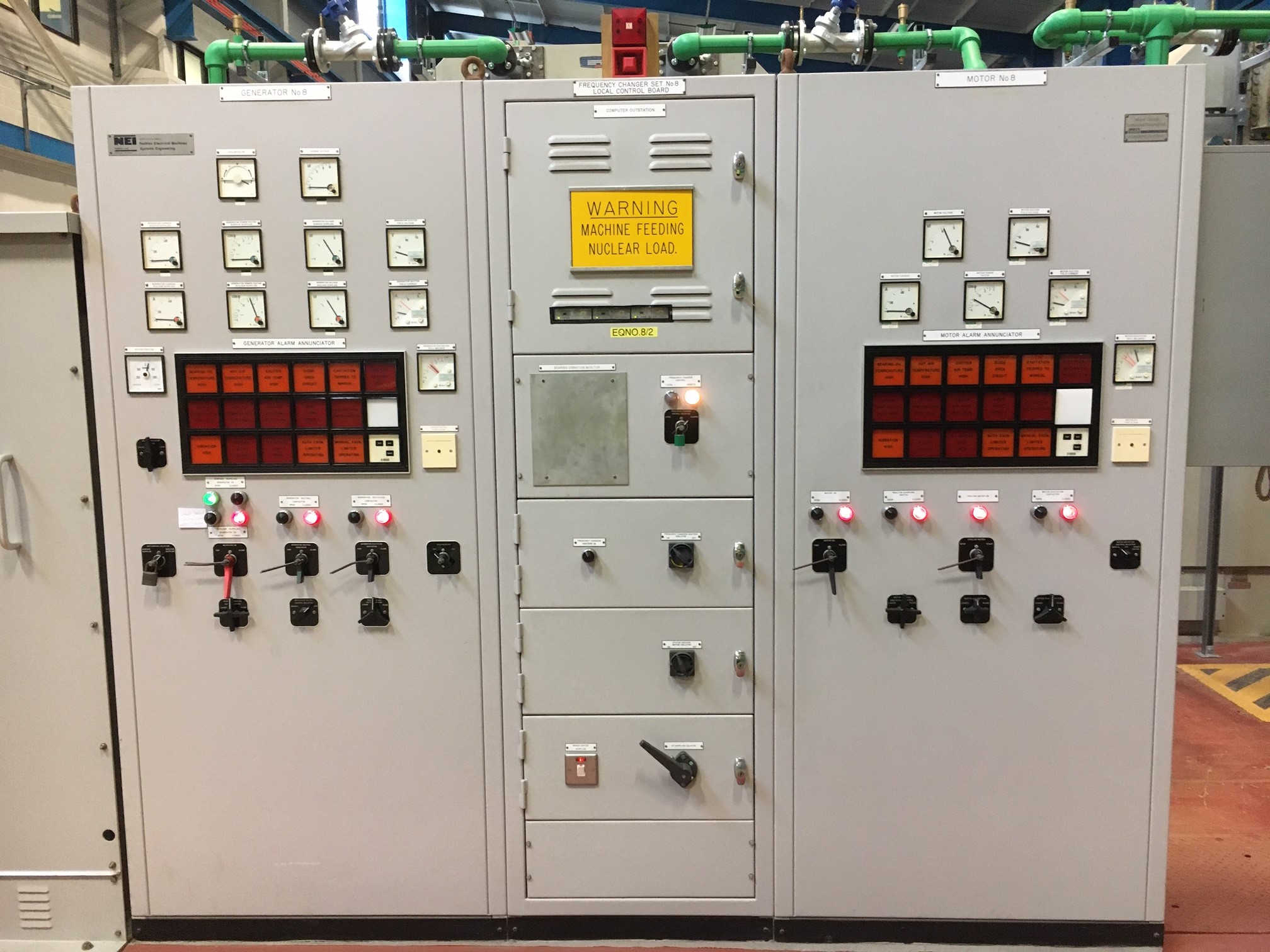
Frequency Converter Front Panel
Each of the sets uses a 50 Hz supply to produce an output of 60 Hz through the use of a “common-shaft” converter. Frequency conversion is achieved by winding the motor with a different number of electrical poles than the generator. A 10-pole motor and 12-pole generator are used to provide the conversion from 50-60 Hz . Using a synchronous drive motor ensures the frequency is maintained at a constant level to ensure power quality. Rotary units are selected as they are more reliable than solid state converters which create a synthesised output voltage and are prone to unwanted harmonics.
The sets give off a lot of heat which means the building requires heavy ventilation and the units themselves are served by a water cooling system which can be seen by the pumps and green pipework shown dotted around the installation.

Circulation pumps for Frequency Converter cooling system
The 60 Hz supplies are then distributed via what I was told is the largest switch-room in Europe (citation needed!).
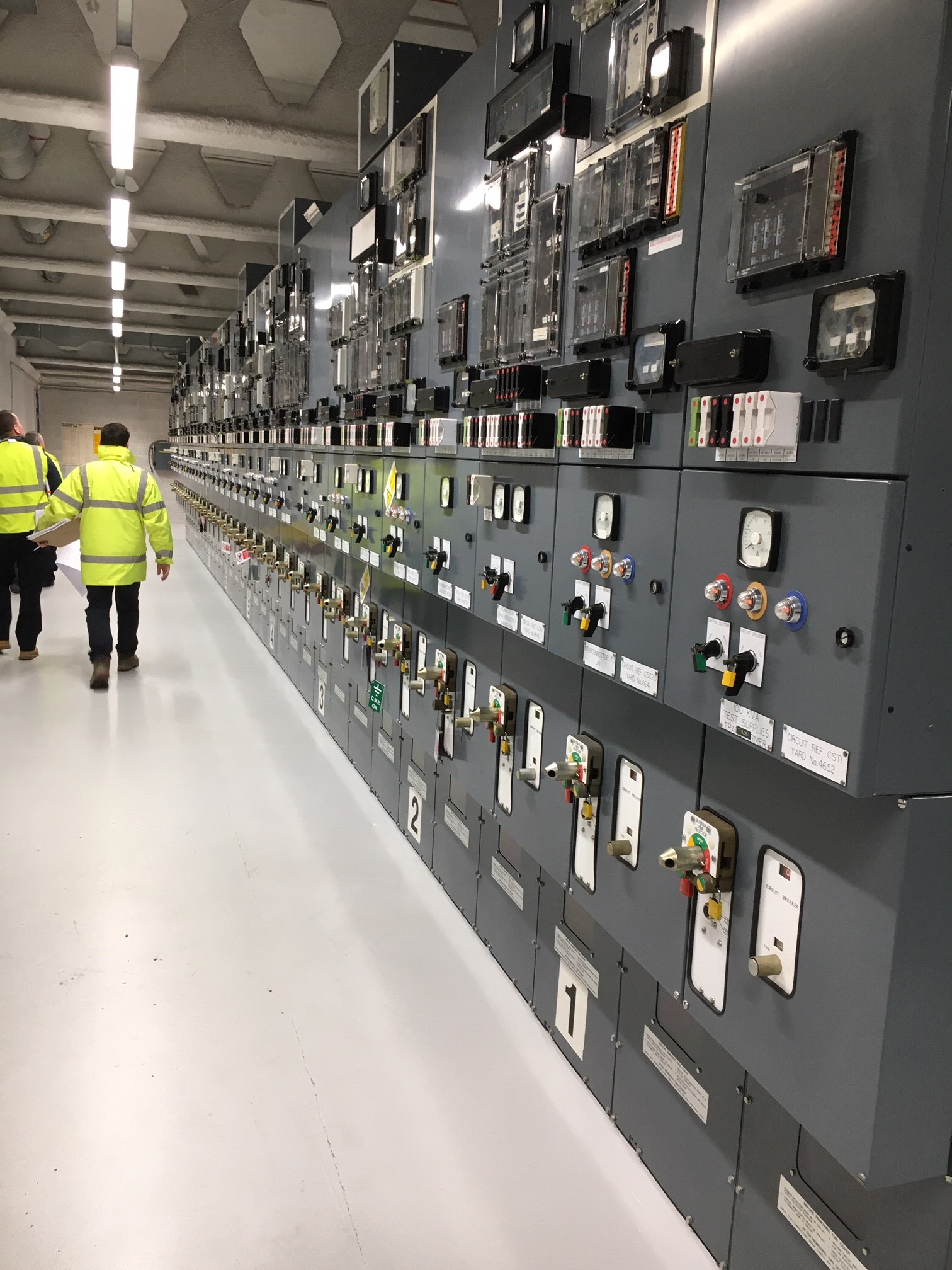
Dockyard Shore-to-Ship Electrical Supply Control Room
Just as a side note – A higher frequency is the preferred choice for many applications as motors and generators which run faster, have a better power to weight/size ratio and therefore take up less space. The same reason is why the aviation industry uses 400 Hz – smaller, lighter components for the same shaft power output.
What other locations or facilities are people aware of that have different supply requirements? Have you seen any “funnies” on your travels so far?
The Great Escape
I’ve been supervising a fun little job on my project in the City and remembering Ash’s CI’s Paper presentation on tunnelling I thought I would share.
The challenge is to connect the new building into the existing sewer which lies 10m beneath the junction of Bishopsgate and Leadenhall Street – two of the busiest roads in the City. The process will be to break through the secant piled basement box and tunnel under the road to find the sewer under the street.
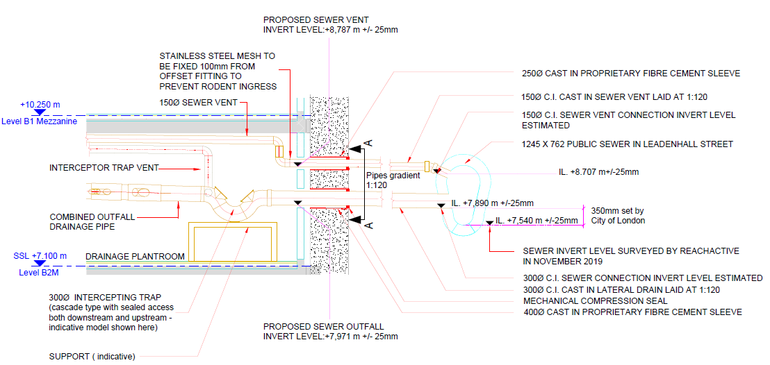
Cross section through proposed connection
There is however no fancy machine option for this job and the solution will be good old fashioned timber heading or mining. This is pretty much the exact process seen in The Great Escape and, judging by some of the characters who do this work, I don’t think H&S attitudes have advanced much since then (see video link at the bottom).
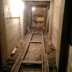
Example timber heading
Timber headings like this one are surprisingly common still, especially in London, so we had a few examples to follow as well as the British Tunnel Society guide “Traditional Timbering in Soft Ground Tunnelling”. What makes our tunnel a bit special is the need to dig through River Terrace deposits rather than the preferred London Clay. The BTS guide makes it very clear that this is seriously sketchy and lays out a load of extra considerations but, in short, it can be done.
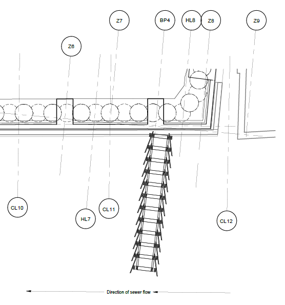
Dig line from the basement box to the sewer
The general method of timber tunnelling is portrayed quite well in this cartoon though our tunnel will need to adopt the Newcastle tucking frame method for use specifically in granular soils.
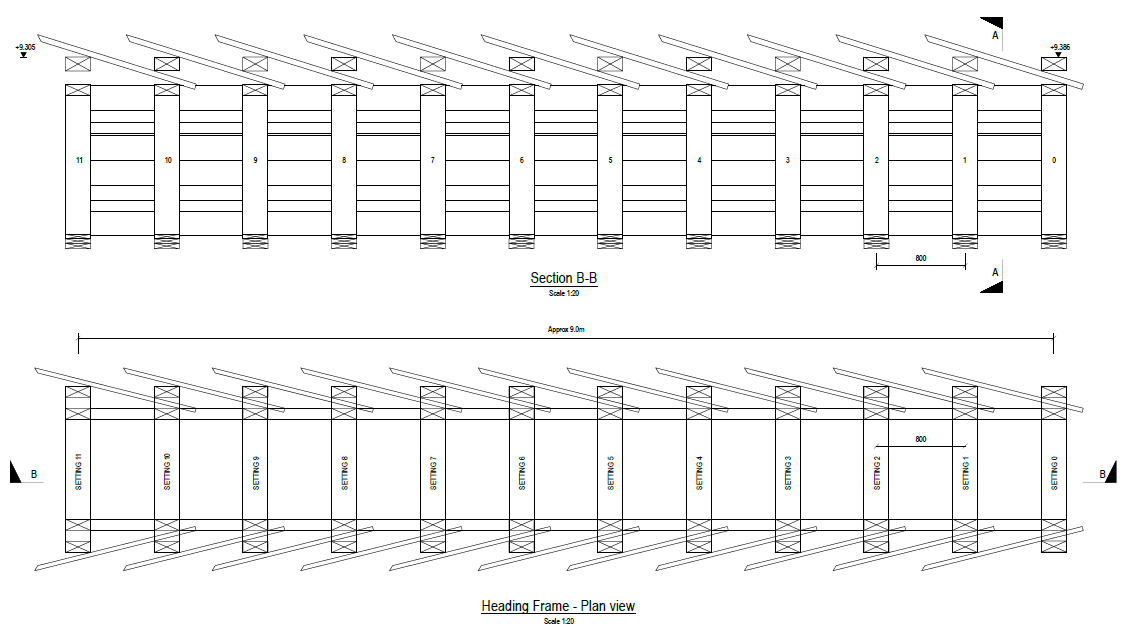
Newcastle tucking frame heading design
For the unmissable, immersive experience check out this time-lapse video of some nutters digging one of these tunnels. It needs sound but is well worth it.
Next year’s PCM exam?…
In Melbourne there is currently a situation straight out of Greg Tripp’s PCM exam…
Project Setting:
The West Gate Tunnel Project is an A$6.7 Bn portfolio of projects to improve East-West journeys through Melbourne with a target completion date of 2022. The project is funded by the Victorian Government who has employed a private company (Transurban) to deliver the project. In the project setting Transurban is acting as the Client. The designers are an Aurecon Jacobs JV (AJJV) and the contractor is a CPB and John Holland JV (CPBJH). AECOM and SMEC have formed a JV (ASJV) to fulfill the Proof Engineering role.
The problem:
The tunnel alignment runs through a site that was previously used as the Country Fire Authority’s Fiskville training college. The site was known to contain soil contaminated by PFAS (Per/Poly-Fluoroalkyl Substances) which was used in legacy firefighting foam. The college closed in 2015 partly due to the PFAS contamination risk.
I understand at the time of signing the contract, the Client and Contractor JV were aware of the presence of the PFAS. However, since signing the contract, the Australian Environment Protection (EPA) Agency has classified soil containing PFAS as contaminated material. Despite determining PFAS as contaminated waste, the EPA has not issued a classification for the waste which means it cannot be transported off-site for disposal. Consequently, the TBMs have sat at the bottom of their entry shafts for 6 months and not moved an inch and over 130 staff have been laid-off.
Although I have not seen the contract, the media is reporting that the Victorian Government’s contract with Transurban transfers the risk of soil contamination onto Transurban. As the issue has not been resolved after 6 months CPBJH has notified Transurban they wish to terminate the contract arguing a ‘Force Majeure Termination Event’ (an event beyond the control of both parties has occurred preventing a party from fulfilling their obligations). Despite the commercial dispute works continue on-site and in the design offices.
The Stand-Off:
CPBJH’s intention is to negotiate a new contract for the completion of the remaining works.
Transurban disputes CPBJH’s notification and is arguing the contract remains valid.
The government is arguing that Transurban and CPBJH must resolve the dispute and the project must still be delivered on schedule.
The workers union is putting a lot of pressure on the Victorian Labour Government due to the number of workers affected by the delayed works.
What do you think?
- Who owns the contamination risk?
- Was the contamination foreseeable to the Contractors?
- Does CPBJH have a right to claim a Force Majeure Termination Event?
- Who should bear the cost of building a new contaminated waste disposal facility for the PFAS contaminated waste material?
- Should the EPA bear more responsibility for the impact on-site?
- How involved in the resolution should the Victorian Government be in the resolution?
- Where do the AJJV and ASJV stand if they conduct design and review work after CPBJH has notified Transurban of their intent to terminate the contract?
- Dan you worked on this project. Any inside thoughts?
Government Warned 6 Months Ago
West Gate Tunnel Builders Seek to Terminate
