Covid-19 Response; Temporary Hospital Design (Exeter)
You will all be familiar with the extraordinary efforts currently going ahead to complete the 4000 bed NHS Nightingale Hospital in London. Although on a smaller scale, my design office has just been stood up en-masse to provide designs for a 500-bed facility in Exeter. Whilst waiting for the URD to be issued, we’ve all been briefed to familiarise ourselves with the requirements specified in the document:
Having reviewed the document and other relevant sources*, I wanted to give a bit of an overview of what is required from an E&M perspective, as I think the design considerations would be of particular interest in the current climate.
All Patients with suspected or confirmed COVID-19 should be placed in single rooms as shown below.

The following design requirement/ considerations are per treatment room;
Medical gases:
- Patients will need continuous medical care using piped medical gases.
- The design must be factored around the source of supply; bulk liquid oxygen plant/mini tanks/portable cylinders.
- Medical oxygen supplies must achieve a flow rate of 10 L/min, per bed (implied task; check and confirm all distribution pipe sizes).
- Distribution systems must alarm if pressure drops below 3.85 bar
- Medical air manufactured using compressors on site. It is required for driving ventilators and is supplied via a dedicated pipeline system. In addition, medical air cylinders are normally used as an independent back-up supply.
Fire:
- The use of ventilators will result in increased oxygen levels with increased risk of combustion, which should be factored into a fire risk assessment.
- Temporary fire-stopping should be provided for any wall or floor penetrations.
- Automatic smoke detection is required
HVAC:
- The density of ventilators may enrich the air with oxygen, increasing the combustion risk. To mitigate this risk the level of air changes through natural and mechanical ventilation must be maximised to lower the oxygen level to <23.5%
- Where locations are considered “early stages” or “high-risk”, patients with COVID-19 should be isolated in “negative-pressure rooms”. The recommendation is to use portable suction units which can be removed and sterilised.
Small power:
- Each treatment room requires –
- 4 x twin 13A switched sockets
- 1 x 13A cleaners socket
- Each room has a number of electronic equipment, including ventilators, for which the combined loads will need to be calculated. Diversity will be minimal as all systems will run at the same time.
Lighting:
- Each treatment room requires –
- 20-20 lux general illuminance for night-time
- 1 x 1000 lux adjustable examination lamp
- Emergency escape route lighting required: In accordance with BS 5266 and HTMs.
Domestic Hot and Coldwater:
- Each treatment room requires a hand wash basin, which should be fed through a mixer tap.
- Max hot temp = 41 dec C
- Max cold water temp , 20 dec C
- Max pipework surface temp = 43 deg C
The above detail is just taken from the one document, but the HTMs go into much more detail and will provide the basis behind any designs.
I’m sure you’ll agree there’s quite a lot to think about there… and I’m looking at 500 beds, not 4000! As a standard project, on standard timelines, all of this would not be too challenging but when considered this is all to be completed within 10 days, you can imagine the challenges with design, supply, installation and commissioning. Not to mention the unprecedented level of collaboration and coordination required.
Although the treatment room designs can be replicated for each room, the distribution and containment networks for small power, lighting, water and medical gases will require careful consideration.
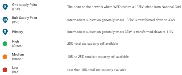
A major consideration will be the availability of supply from the local utilities companies and medical supply chains. The newly appointed site would have a much higher usage of water, electricity and gas. It will be important to calculate the requirements and engage with the utilities companies to ensure that the demand can be met. I know from recent experience that Exeter does not have a great deal of spare capacity in the electrical grid as shown below;

Hopefully, this has been of interest and given you some insight as to what is expected, with what I suspect might be the first few of many of these sites.
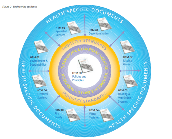
*A list of all relevant Health Technical Memorandums (HTMs) and Health Building Notes (HBNs) can be found on the UK Gov website HERE, but as a rough guide;

It’s probably worth emailing me at Henry.crosby516@mod.gov.uk and I can send you over some reports from other recce teams etc. You will be going into more detail than the STREs so the information will probably flow two ways pretty quickly. My mobile number is 07904105467.
It’ll probably make a good TMR/AER too!
Jamie
A few starters for the Med Gases:
The method and sizes are detailed in HTM 02-01 including diversity although your attachment seems to suggest there is no diversity considered for C-19. If all patients are drawing simultaneously then the HTM guidance may not be extant however I’d be surprised if that was the case.
HTM 02 also details the number of AVSUs and TUs you require (Area valve service units and terminal units). In ITUs its normal to have 2 AVSUs per gas with dual piped supplies. As well as LP alarms you’ll need plant room repeaters and alarm panel in a manned reception area for bottle contents (LP alarms only indicate to clinical staff that there’s a problem and they will be busy with other things).
Compressed air for MA4 and MA7 supply is straightforward, NHS compressor plant rooms are pretty much templated as is Vacuum. See my “typical systems” on the ELE. Cylinder back ups are pretty much useless where so many ventilators will be used but should be in a separate plant room nonetheless.
For all +ve pressure gases pressure drop is no more than 5% with (normally) 4 bar at the outlet.
Pipe sizes should be 12 or 15, 22 in distribution, 28 in branches and 35/42 in risers, standard way to size is to work to those sizes as an assumption (the catch 22) and if it works then leave it.
Hope there some threads there that will help, always at the end of the phone etc.
Easy way of assessing currnet O2 capcity is to look at teh amount of evaporator section connected to the VIE. The standard evaporator gives 500 l/min at full flow.
Thanks Henry, Thanks Mark 🙂
Jambo you legend – just started on the Sydney version of the above. Will be in touch!
The ICE is running a free webinar on the London Nightingale hospital at 1330 on 30 April and apparently they have someone from the Armed Forces down to speak. The link to the ICE is here or just search on the ICE website if you want to sign up:
https://www.ice.org.uk/events/lunch-and-learn-engineering-nightingales-webinar?utm_source=Communicator&utm_medium=email&utm_content=Untitled15&utm_campaign=Pitch+200+update+London++21.04.20&_ccCt=_OJFvFSXdWX5A989VZDzsy_0nl2upASIKRT7u6BjWEA_P4J2i9V0H4BLdDPXGoSX
Might be a stupid Q ..probably is … Does is the power demand associated with the E&M described above easily supplied…in other words is it one of the key selection criteria for a particular site….if not what does drive the selection? If rooms have to be depressurised, for example,, are standard BReg air sealing requirements entirely adequate?
John, as you can imagine there are a number of key criteria, but you’re right to identify the power as a potential show-stopper. Following the HTMS for the technical spec and the HBNs for the overall requirement, there is certainly a bit of a balancing act as to what is the ideal, and what can actually be achieved.
Whatever the approach, the design must allow for maximum resilience, so will require a Primary Electrical Supply (PES) – which is generally the DNO supply, a Secondary Power Supply (SPS) and a tertiary power supply in the form of an Uninterruptable Power Supply (UPS) for all “critical loads”.
In the requirement for the PES, there are a number of desirables to maximise resilience; The site should ideally be fed from two separate supplies from separate parts of the grid, but each one of these supplies must be able to support the demand profile for the site on its own – the HTMs talk of “N+1” e.g.if you’re demand for the site is 2MVA, you’d ideally have 2 separate DNO supplies each cable of providing 2MVA from each. The N+1 principle should then be applied to the distribution and switchgear, SPS and UPS; so 2 x separate transformers capable of taking the full site load each.
What really adds a level of complexity is trying to project the site demand profile, to allow you to work back from N+1. For critical care bed spaces, we’re looking at 12.5 Amp per bed, so 3kVA each (240 x 12.5), with zero discrimination. This will vary depending on the type of ward. Power also needs to be factored in for the VIE controls, compressor plant, mortuary services (read refrigerated ISOs), welfare facilities, ambulance depots, and the next big challenge; HVAC.
Lots of the proposed sites are big open warehouses, that under normal operations use gas-fired radiant heaters. Due to elevated O2 levels, these cant be used due to fire risk, so you would need to generate the building’s heat through another method. In the site’s ventilation strategy, you’re aiming for 10 air change rates (ACRs)/ hour, whilst maintaining 22 deg C. Depending on what the ventilation strategy is, it will be a challenge to meet 10 ACR in such large open spaces, and then difficult maintain the temperature as you’re moving a lot of air through the building. If electrically generated, the heating load will add a lot more to the demand.
In attempting to achieve negative pressure in the ward area for contamination control (minus 8-12 Pascals as per HTM), you can make calculations to have extract fans giving a bit more than the fans feeding the building, but the unknown here is the infiltration rate of the building – probably very “leaky” and not at domestic Building Reg standards. This leakiness means you might not achieve the desired pressure drop, which means cranking up your extract fans until you do… which means more power.
It’s also worth noting that in the instance any clinical spec required under the HTMs cannot be met, this needs to be recorded on a “derogation register” and signed off by the NHS Trust to accept the residual risk. A proactive approach is needed here as any delay could see your proposed design NOT be accepted in the latter stages, with wasted design resource and potential for delay.
All combined… you have a fairly wicked design problem.