Archive
Ground Improvement through Jet Grouting
Jet Grouting
Jet grouting is a construction process which employs a high kinetic energy jet of water to break down a soil formation into suspended particles and mixes the in-situ soil with cement grout. This process of hydrodynamic erosion of the soil and mixing forms a soil-cement mix which has improved properties. There are three distinct phases to the process (see Figure 1):
- Breakdown of soil formation using high-pressure jet. A borehole (90-150mm) is drilled to depth and fluid is pumped at a pressure >450bar to the base of the drilling rods to breakdown the soil formation.
- Introduction of grout. The rods are rotated slowly as they are extracted from the borehole and cement is pumped from the base of the rods simultaneously. This creates a column of soil-cement mix, evenly distributed through the treated volume. This phase of the process uses a computer to control to extraction speed, rotation, grout pressure and grout flow.
- Displacing of excess material. All excess soil-cement mix exits freely to the top of the borehole and removed. The pressure is stopped 500mm below ground level.

Figure 1 Jet Grouting Technique
Requirement at Australia 108
The scope of works for the Australia 108 project was to provide a jet grout plug from RL -7.0m to RL -8.0m to act as a strut against the core retaining wall and reduce estimated deflection during excavation. This would enable a 6m deep excavation from RL -1.0m to RL -7.0m without the requirement for walers and struts. It would also serve as a plug to reduce water ingress into the excavation. In total 106 jet grout plugs were placed varying in diameter from 1.4m to 2.2m, (see Figure 2). The ground conditions from RL 0m to RL – 17.0m is Coode Island Silt which is soft to very soft silty clay with high plasticity. The GWL sits at RL 0m. Menard Bachy secured the contract for these works.

Figure 2 Jet Grout Column Arrangement
Trial Works
The strength of the grout mix will be tested to confirm that 2MPa has been achieved at 28 days based on cubes sampled daily from the spoil return. It is possible to core the jet grout plug in situ and test but it is preferrable not to. Instead trial works were done prior to production of the core plug. The aim of the trial was to allow commissioning of the grout batching, pumping and drilling equipment and to ensure that the columns are consistent with the design assumptions.
Six jet grout columns were arranged as per Figure 3 to achieve overlaps of 400mm between 1.4m and 2.2m columns, and overlaps of 300mm between 2.0m and 2.2m columns. The trial columns were installed at the same depth approximately 10m away from the permanent location. The overlaps were cored and visually inspected to check for integrity prior to commencing the permanent works (photo of core sample at Figure 4). It was assessed that close to 100% of the Coode Island Silt had been replaced by grout and that the overlaps have been achieved.

Figure 3 Trial Column Arrangement
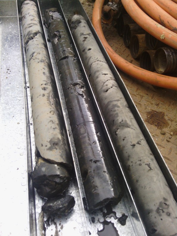
Figure 4 Photo of Trial Column Cores
Risks
The greatest risks with this method are as follows:
- Not achieving required depth.
- Not achieving column depth.
- Incorrect drill location resulting in insufficient overlap between columns.
- Damage to near-by structures and uplift due to the high pressure and flow rate.
To mitigate these risks, the jet grouters rely heavily on computer control and monitoring. The operators are given design parameters from the engineers and they ensure the equipment is calibrated and they adhere to these parameters; they provide a drilling record for every column as part of the QA process. They also drill approximately 100mm above and below the target depths to ensure there is a consistent band at the required depth. They also use GPS and surveyors to locate the boreholes pre drilling and provide an as built post drilling record. If a column is installed in the incorrect location or depth, the process can be repeated in the correct location as the pressure is sufficient to erode the soil-cement mix.
Method Statement and photographs
I have included below a simplified method statement to demonstrate the how the jet grout plug is installed prior to the core raft, as well as numerous photos so you can see how the actual construction process looks. In practice, it took a lot of co-ordination on site as the site set-up and trenches to remove the fluid spoil were a considerable laydown. Interestingly though, one thing I couldn’t capture well on photo was how much the ground bubbled due to the sub-surface pressures created by the process.


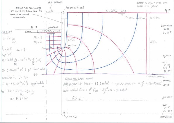
Flow Net

Flow Net Take 2
SIMPLE SOLUTION TO A SEEMINGLY SIMPLE PROBLEM?
So drilling through a basalt extrusion proves rather problematic when the drilling arm to your rig snaps off and you are unable to recover it. You are essentially left with a snapped arm 20m deep in what should be a 1500mm pile which is now unusable.
The piling subcontractors are on a design and build contract; they caused the problem, they will fix the problem at their cost. The solution, endorsed by the Multiplex team overseeing this part of the programme, is to concrete the original pile borehole (BP38) and construct two further piles (BP38-1 & BP38-2) either side of BP38, designed to carry the same loads. Simples!!
What risk did they fail to see?
The position of BP38 is close to a secant pile retaining wall which is approximately 3.5m from the site boundary. There is a heritage façade which sits on strip foundations on the site boundary which is already in a pretty ropey condition and only supported laterally. The northern retaining wall enables excavation down to Basement Level 1. The construction of BP38-1 & BP38-2 was designed by the subcontractor’s engineer; construction went without a hitch and the two 1200mm bored piles have sufficient resistance equal to the original pile.
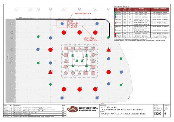
Position of BP38 in relation to site boundary and façade, and the northern retaining wall
Problem: It turns out that when you adjust the position and number of piles beneath a pile cap it alters the pile cap design. Funny that! The structural engineer (a consultant) produced a new design for a 1.6m x 5.4m x 3m deep pile cap to ensure the load (37MN ULS axial load) could be safely transferred to the piles. This means that an excavation of >3m is now required to construct the new pile cap. This is a >3m excavation in soft Coode Island Silt within 1.5m of the heritage façade.
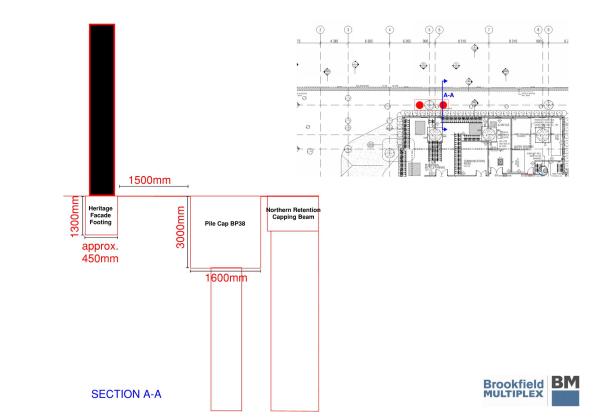
Cross section detailing the parameters of the problem
Unidentified risk: This is an obvious example of unidentified risk, which could easily have been identified. Two subcontractors responsible for two areas of design and construct have not communicated before adjusting construction plans due to a foreseeable problem – everyone knew the basalt was in that location. The geotechnical subcontractors have simply fixed the problem they caused, thereby fulfilling the terms of their contractual obligations, without due consideration for the next phase of the programme, i.e. the construction of the pile caps. Multiplex have ratified the change because, I would argue, the people overseeing the construction have not understood and/ or identified the second order effects of the change.
Discussions: The first time I was enlightened to the problem was when the co-ordinator (construction manager) overseeing this phase of the programme sat getting rather stressed at how he was going to solve it. After two hours of ‘it will be fine’ and ringing round for advice he sent me the specifics when requested to have a look at. Two heads are better than one.
Options on the table:
- It is obvious that the excavation cannot be conducted to that depth without retaining the ground which supports the façade. But the question was how? My recommendations:
- a) Stiff retaining wall functioning as a cantilever capable of withstanding lateral earth pressures and deflections (combi wall perhaps?). This would give clear space in which to excavate at the front of the wall but would require greater efforts to construct such a substantial retaining wall. Also very risky due to the absolute necessity that the façade cannot move.
- b) Prop a sheet pile wall using ground anchors so the load is transferred to the ground behind the wall. Due to the proximity of the boundary (<1.5m) I deemed this infeasible; there would not be sufficient space within the boundary to fix the anchors behind potential slip surfaces.
- c) Prop in front of a sheet pile wall bracing against the northern retaining wall. This is very feasible ensuring that sufficient space is retained to permit excavation.
- Review the pile cap design with the intent of reducing the depth of the pile cap and subsequent depth of the excavation. This may have been an option prior to the construction of the two piles, but unlikely to be feasible now the location of the piles is fixed. A retaining wall would still be required but to a potentially shallower depth.
The solution: I recommended Option 1c as the way to go, pushing the piles where possible rather than vibro. The piling subcontractors are responsible for the design and construction of any temporary works to enable the excavation but were holding off to receive direction from Multiplex. Multiplex in turn has sent the problem direct to the geotechnical engineer consultants for their advice. Their recommendation: Option 1c.
Timing: The problem was first identified by the groundwork subcontractor on receipt of the new design drawings of the pile caps. This was on Friday, nearly three weeks after the failure to construct the original piles. Construction of the pile cap was due to commence on Tuesday giving 1 working day to come up with a solution and have the designs authorised. Needless to say, it is now Thursday and the team are still waiting on the design from the piling subcontractors and work is yet to commence on the retaining wall.
Lessons learnt?
- Communication is vital when the work being conducted by one subcontractor affects another.
- Second + order effects must be considered prior to making any amendments.
- Identifying risk early and consider this risk in re-mediation plans.
Additional remarks: In this case, the solution would likely have still been the same had the problem been identified when the original pile was deemed unusable. The upshot of early identification was that a retaining wall could be have been designed early and constructed immediately after the piles, thereby causing no delay to the construction of the pile caps.
CLOUD BREAKING DESIGN – AUSTRALIA 108
‘Australia 108 is a highly sculptural residential tower unlike any other in Australia. Its slender form is highlighted at the Cloud Residences levels by a golden star burst expression and then morphs into a curvaceous profile against the sky. The star burst which contains the resident facilities is inspired by the Commonwealth Star on the Australian flag and is an obvious celebration of the sense of community within the building’ – Fender Katsalidis Architects
This is what it looks like now….

This is what it will look like in 2020…

Project Overview: Australia 108 will be a 319m, 100 story residential building in Melbourne. When complete, it will be the tallest residential building by roof line in the Southern Hemisphere.
It is a design and build, fixed-sum contract to the value of $500m AUS. There is one basement level, one level of retail, 10 podium levels for car parking and the remaining floors to level 100 will be residential and amenities. To note the penthouse has sold for $25m AUS (equivalent to £12.5m) to give an indication of the quality and desirability of this build. Site preliminaries commenced in late May 15 and the foundations in Oct 15. The basement structure is due to finish in Sep 16 when construction of the superstructure should commence. If all goes to plan, the project should be reaching the soaring heights of level 10 by Christmas.
The 60 x 45m site is located on Southbank Boulevard approximately 300m from the Yarra River. It is situated on poor quality river deposits of soft silt and river gravels down to circa 35m where a medium – slightly weathered siltstone with good engineering properties is located. All high rise buildings in this area, bar one, have been constructed with podium levels above ground to house the car parks and to minimise the depth of excavation; this building is no different. There will be an excavation to a depth of one basement floor under the building footprint with a lift overrun under the core to a depth of two basement floors. Due to the available space on site, the majority of the excavation is being conducted by battering back the ground. Secant piling is being used for the core excavation and to protect a heritage façade from settlement. The groundwater was identified at a depth of 3.25m (RL -1.15m) during the site investigation but it is anticipated it could reach RL 0.0m from historical records.
The foundations are being constructed from replacement piles. The bored piles range in size from 2100mm to 1200mm dia. A polymer fluid has been used to support the bore holes until concrete pour. The remainder are CFA piles of either 900mm or 600mm dia. The only major issue encountered has been reduced boring rates due a narrow band of basalt in one corner of the site; this was factored into the programme and the subcontractors are on track to finish on time. Due to the poor engineering quality of the upper ground horizons, the piles rely heavily on base resistance and are designed with a socket length into the rock. This socket length is calculated to ensure that settlement of the pile is within tolerance under SLS loads, and is sufficient to resist any tensile force acting on the pile. Quality assurance is high to ensure that the design resistance is fully mobilised.
My Roles
1. Jet Grouting. I have arrived close to completion of the piling and the excavation commences next week. A geotechnical specialist, Menard Bachy, arrived on site today to do ground improvement works prior to the excavation. They are providing two functions: the first to place the soft piles in the secant walls by jet grouting columns between the hard piles; the second to jet grout a 1m thick water-reduction plug at the base of the core excavation. While this will not completely water proof the excavation it will significantly reduce the inflow of water to negligible levels. The ground slab will be poured on top of the grout plug. I have been tasked to work with the sub-contractors and provide the co-ordination, progress tracking and QA for this part of the project. It appears to be quite an interesting method having done some back ground reading on the subject, so I will maybe do a separate blog on the topic once I’ve spent a bit more time with the sub-contractors.
2. Starburst Co-ordinator. The starburst is the yellow clad star at levels 69-71. This will house plant at level 69 and residence amenities, including infinity pool, at levels 70 & 71. It will cantilever approximately 8m from the superstructure. At present this is a preliminary cost and has yet to be designed. A little headway has been made on the permanent structure by the Structural Engineers and a method statement has been drafted by a senior site manager. The two do not correlate and the initial work was only produced in order to submit a bid for the project. It is expected that the current proposal will radically change. I have been assigned the task of Starburst Co-ordinator, much to the relief of the other graduates. My role is to co-ordinate the ‘meeting of minds’ including those belonging to the structural engineers, steel consultants, concrete sub-contractor and the ‘brain’ from Multiplex’s Engineering Innovation Group (EIG) who is a world leader in high load structural connection design (James Murray-Parkes – google him). The aim is work out how this starburst is actually going to be built, produce the method statements, track progress and keep momentum on this part of the project and ultimately work with the commercial team to put the construction of it to tender. It will be a fantastic challenge although I will be long gone by the time construction actually commences on this part of the structure.


Particular notes I have found of interest from week one:
1. For a record breaking construction project, there are no engineers in the Multiplex team working on this project. The graduates are all project co-ordinators who all have construction management degrees. I will be working closely with the ground co-ordinator and the structure co-ordinator. They understand a lot about construction, obviously, but their technical knowledge is somewhat limited. I am waiting for a meeting with the structural engineer consultants next week to ask some questions which to date have gone unanswered.
2. The influence of the unions. The strength of the unions in Melbourne is staggering and they have significant influence over the execution of projects. If it hits 35 degree – work stops. If it rains (and I mean light rain) – work stops. If there is even a minor breach in H&S – the senior union representative can close the site (the project office remains open though so I don’t get an early knock off). It is a very interesting dynamic between the management team and the union reps, one which I will watch with interest.
I’ll keep you all posted 🙂
