Archive
In my last blog I talked about the use of the top down construction methodology in the construction of high rise towers. It presents a number of considerable structural challenges which have resulted in a quite unusual and, so I’m told, unique construction sequence on our project. A senior design consultant from Sydney, Australia who is now working in the London structural engineers office confirmed that view of Friday morning when he described the 100BG basement as engineering insanity. Therefore, as it’s a Wednesday and because pictures are far more interesting than my boring text, see below some images outlining current progress.

Fig1: The concrete core, allegedly one of the largest currently under construction in Europe, is paused at a temporary hold point on floor 8.

Fig2: The full vertical load of this core is carried through steel plunge columns which are cast 5m into large load bearing concrete piles just below dredge depth. Interestingly we were able to excavate the Tower basement to 2.0m OD from 15.0m OD without use of any temporary internal propping regime.

Fig3: Sheet piles have been installed around the edge of the plunge columns to allow further excavation of the core pile cap to a depth of 0.0m OD. The Tosa pushes 6m long steel sheet piles in at a rate of approximately 24 per day. The 4m embedment seems more than sufficient to me considering they are in stiff London clay and are for the temporary condition only.

Fig4: Pile Cap excavated to depth in stiff london clay material. The water table is approximately 6m above dredge depth but ground water has not presented any issue during any stage of this excavation.

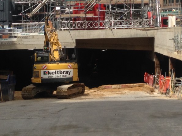
Fig5: Machinery breaking out the top of the core concrete piles in preperation for construction of the core pile cap. In the back right of the image you can see a column where the process of pouring the concrete caused the rebar cage in the column to rise in the pile shaft.

Fig6: Tower secant pile wall restraint
Project Update: A Relentless Pursuit for Cost, Quality and Time
Now TMR1 and Thesis Form A’s are out the way I thought I’d provide an update on placement progress and a few of the issues we have encountered along the way. As my title suggests many of these are occuring because of the relentless pressure on the construction team to deliver the project as quickly, cheaply and to uncompromisingly high quality . As we know from phase 1 something probably should be prioritised, unfortunately that doesn’t appear to be a well received strategy on site.
As you may recall (probably not) from my first blog we are using a top down methodology on the main Tower structure. Underneath the large Ground Floor (GF)slab we have unleashed the earth work contractors to crack on with the bulk excavation, taking our basement level from 9.0m OD to around 2.0m OD at its greatest point. This is a twelve week programme based on a target of moving 100 spoil vehicles away from site each day. The largest obstacle to this operation is not the digging or site movement of spoil, it is actually getting enough vehicles to and from site despite the constant challenge of breaking through London traffic. As such much of the earth is moved away at night which is probably proving a delight to our few local residents. To the sub-contractors credit they are doing well; they have their own exclusion zone so everyone else is able to keep out the way, which is useful considering the large number of excavators and dump trucks rattling around below our feet. Now they are underway tempo is impressively frenetic and as a result the ‘Bat Cave’ is taking shape nicely.
![IMG_0246[1]](https://pewpetblog.com/wp-content/uploads/2016/06/img_02461.jpg?w=595)
![IMG_0241[1]](https://pewpetblog.com/wp-content/uploads/2016/06/img_02411.jpg?w=595) The challenge of starting this process did throw up a nice on site leadership issue. After four weeks of hard work thrashing themselves to get the basement ready for commencement of this excavation , which they achieved, the junior construction team got a harsh email from a senior manager criticising quite a few trivial things on site. This inspired a near mutiny and, for a few days, a very inharmonious working environment. It was remedied by an honest, open conversation between various levels of management. One of the junior managers (not me I should add) fluctuated between near tears and incandescent rage when explaining his disapproval of the heavy criticism the on-site construction team was consistently receiving from, in his words, ‘Office bound desk jockeys’. Add a few favourite Aussie expletives in there behind the word jockey and you get the gist of his point. Everyone is now friends again, for the moment, but the unrelenting pressure applied by the project management team is starting to take its toll on morale. We shall see how long the current truce lasts.
The challenge of starting this process did throw up a nice on site leadership issue. After four weeks of hard work thrashing themselves to get the basement ready for commencement of this excavation , which they achieved, the junior construction team got a harsh email from a senior manager criticising quite a few trivial things on site. This inspired a near mutiny and, for a few days, a very inharmonious working environment. It was remedied by an honest, open conversation between various levels of management. One of the junior managers (not me I should add) fluctuated between near tears and incandescent rage when explaining his disapproval of the heavy criticism the on-site construction team was consistently receiving from, in his words, ‘Office bound desk jockeys’. Add a few favourite Aussie expletives in there behind the word jockey and you get the gist of his point. Everyone is now friends again, for the moment, but the unrelenting pressure applied by the project management team is starting to take its toll on morale. We shall see how long the current truce lasts.
Above the GF slab we have commenced structural steelwork on the main Tower, another key milestone. On Saturday six 20 Tonne steel columns were erected with a mobile crane. This was all going well until they realised that the lifting plates, temporary steel lifting connections attached to the head of each column, were fabricated in the wrong orientation. Fortunately, with use of a heavy duty steel drill and an extra few hours the issue got fixed and the columns were placed upright in the correct position. Drilling extra holes into precision fabricated steel elements on site isn’t an elegant solution but it worked. Now the columns are in place steel beams are starting to fly in (not literally of course) and the skeleton of the ground floor structure is rapidly taking shape. The steel erection is surprisingly quick and they are clearly a well-rehearsed team. Floor one will hopefully be complete in a few weeks, at which point we will have only 39 more storeys to go!


Above the steelwork the east slip form rig of the large central concrete core has begun to rise once again. Its currently at floor 8 and will pause at a pre-determined hold point on floor 10, allowing the western component of this core to catch up. We will not be able to progress the core beyond floor 10 until the pile cap is constructed in the basement. This controls the vertical load through the exposed plunge columns in the basement, primarily required to prevent them buckling which is obviously bad when you have 10 storey’s of reinforced concrete suspended on them. Once the pile cap is constructed the effective length of these columns is gradually reduced which allows us to increase the axial loads and continue the progress of the slip form.
We have also increased the Tower Cranes on site from 1 to 3. To make things more challenging we selected self-climbing cranes, one suspended inside each core. These effectively hang off the walls of the cores and climb up the lift shafts behind the slip form rig. Unfortunately this is reasonably new technology in the UK and nobody really understands the process for each climb or how long it will take. We really are making much of it up as we go along. What we do know is that if we don’t figure it out soon then the slip form rig will catch up with and hit the crane. This is problematic. The other excellent news is that our three cranes are all pretty much aligned on the same axis and therefore clash frequently. Trying to figure out which crane can do which task without impeding other works is like a giant Crystal Maze puzzle with no solution. This problem has an impressive number of intelligent people very confused for most hours of the day.

And in final news we had a very serious accident on site. A scaffold contractor fell roughly seven metres through a hole in the GF slab and into the basement excavation. I’m told that’s far enough to know you are falling before hitting the ground, which is obviously a long way. The investigation is ongoing so I can’t really add anything else other than that his injuries are, luckily, fairly minor considering the distance he fell. He landed on soft, loose soil which was very fortunate indeed. Had he hit the large item of plant located close by it probably would have been a different outcome. Without going into the details it looks like a freak accident, that said it proves the point that if something can go wrong, give it enough time and it probably will. Be careful out there folks!
In summary, tempo is relentless in order to maintain programme, quality cannot be compromised and the cost must be controlled. This all adds up to a very challenging construction project with lots at stake. More to follow once the excavation hits the pile cap OD.
Design of Structural Elements Against Explosive Blast
I mentioned in my first blog that the construction of the ground floor slab is considered a critical milestone. With that for context you would assume that everything possible is being done to ensure the concrete pours on this slab are completed on programme. This brings me nicely on to the topic of this blog.
Early last week, only 60 mins before a significant concrete pour (50m³) was ready to begin on a key part of this slab, an issue was identified during final reinforcement inspections. This caused a fair amount of aggravation and stress on site between the consultant engineers and concrete package sub-contractors .
The issue relates to the column in Fig 1.1 and in particular the depth of fillet welds between the web and flanges. The column protrudes through the GF slab and was scheduled to be encased in concrete up to GF level as part of this pour. The engineer consultant, during his final check of the slab reinforcement bar, identified an issue with the welds on the column that stopped work until the senior structural engineers at the design office could be consulted.

Fig 1.1 – Incorrect Weld Configuration on Column L8
As I know the audience reading this blog adore explosives, and in particular blowing up military bridges on exercise, I thought they might be interested to hear that many of the structural elements have been designed to resist an explosive blast detonated at very close proximity.
Robustness in a building is usually achieved through one of a number of approaches. The most common is to design alternative load paths in case a structural element fails. On this project however, due to a late notice client dictated design change, this was not a viable approach. Robustness is therefore only provided through the alternative ‘protected element’ method. By this I mean key structural elements are designed with adequate individual robustness and additional protective measures (i.e. encased in sacrificial concrete or steel) to ensure they do not fail even when exposed to the designed worst case load condition.
In this particular column the weld design has been specified for this worst case condition. Unfortunately the column was not constructed in accordance with the design drawings. To provide suitable shear resistance in this element, the Blast Engineering Consultants specified a 70mm multi run fillet weld along the full length of the column to the base of the ground floor slab. As Fig 1.1 shows, the steel contractors only installed the fillet weld from the top of the column to the first web stiffener, leaving a considerable length of this column with minimal 15mm deep fillet welds. To try and understand the magnitude and context of the site engineers concern I tried to conduct some very basic analysis of this section.
In the first instance I modelled this problem as simply as possible and effectively considered the column as an I beam bending in one axis with an 8.6MN worst case vertical shear reaction force. To be clear from the outset, it will become apparent later in the blog that this model is far to simple for the complexities encountered in this problem.
Students on the civil stream will fondly remember the “Say It” equation which allows calculation of shear stress along a particular plane at any point in a bending beam. One of the key components in this formula is the thickness (b) of material providing longitudinal shear resistance along the assessed shear plane. The greater the (b) the smaller the shear stress. In steel plate sections a fillet weld exists to simply transfer the shear stresses from the flanges to the web so that the top and bottom flange can work together as a single beam (ie they know about each other). It’s worth noting that because these columns are steel plate girders, there is no monolithic connection between the web and flanges to provide an additional contribution towards this shear resistance. I have simplified the diagram to sum this up and illustrate why the reduction of this weld from 70mm to 15mm might be a problem.

Fig 1.2 – Simplified Column Section Model
Diagram A shows the steel column, as installed, below the web stiffener. Along this length the fillet weld installed is only 15mm in width each side of the web, this provides a total (b) of only 30mm. Diagram B shows the steel column where the fillet weld has been correctly installed. This weld, 70mm on each side of the web, provides a total (b) of 140mm of resistance along this shear plane.
In accordance with BSEN 93-1-8 Para 4.5.2 you actually need to use the effective Throat thickness (a) of each weld in this calculation (This provides a conservative estimate) which can be acquired with some simple trigonometry. I calculated weld throat values of 10.6mm and 49.5mm for case A and B respectively. These figures are then doubled through most of the calculations because we have a weld on both sides of the web.
I then plugged these dimensions and the known constants into the “Say It” equation, with the two different welds considered, to analyse the varying shear stresses induced as a result of the designed maximum blast load occurring on the column:
Calculation Details:
Max Vertical Shear Force on Section Vz = 8.6 MN
Second Moment of Area = 32.77 x 10⁴ mm⁴
Distance from NA to Centroid of Area above shear plane = 200mm
Area above Shear Plane = 38400mm²
Width of Material under shear (Weld Throat): Case A = 21.2mm
Width of Material under shear (Weld Throat) : Case B = 99mm
After I’d run the calcs through using the information above I got the following shear stress values through the welds in each case:
Shear Stress in Weld:
Case A: 950.7 N/mm²
Case B: 203.6 N/mm²
I also calculated the greatest shear stress likely to be seen in the I section for both examples in order to allow further comparison. We know this appears along the NA where the web in this case is 60mm. I ended up with shear stress values as below.
Shear Stress along NA – Web:
Case A: 371.1 N/mm²
Case B: 398.78 N/mm²
When you look at this logically, it raises a few interesting points. In Case A the shear stress expected in the weld is over 2.5 x greater than that seen in the web on the NA. Therefore, when affected by the blast load, the weld is likely to fail long before the web of this section.
In Case B however the weld sees an expected stress that is approximately half the shear stress seen along the NA in the web. In this case it is likely the web would fail before the weld. This suggests the 70mm weld is therefore larger than actually required. Generally a design throat thickness of an I section, doubled to account for both sides of the weld, should be a similar depth as the web thickness on that section. Any additional weld depth is most often unnecessary because the failure risk is transferred to the web.
Using BSEN I then checked the actual permissible shear stress in each weld. In both cases I calculated this to be 230.9 N/mm². When you compare this to the expected stresses, it is clear that the fillet weld in case B is capable of carrying the design stress of 203.6 N/mm² but not the 950 N/mm² of case A; clear indication that the 15mm weld is grossly under strength for the worst case load condition assumed in this model.
I mentioned that my first model kept this analysis as simple as possible. In reality the problem is considerably more complex for a number of reasons. Firstly, I assumed the blast occurred directly perpendicular to top flange. Blasts occurring at different angles to the section would undoubtedly affect the results. In addition to the 8.6MN vertical shear reaction load I considered on the section there is also a 9.5MN axial load from the weight of the building applying a compressive pre stress through the column. Furthermore, the complex nature of the dynamic/impulsive blast load on the section is also far more challenging to categorise; it is affected by numerous variables including charge size and type, stand off, ambient pressure and charge proximity to the ground, amongst others. The response of a steel column to a blast load is also influenced by stiffness, its dimensions, vibration period and strain-rate. The point being, this is far too complex to analyse with such a simple model.
What is very clear is that no one in the project team seems to understand the science or engineering behind the blast design analysis. All we know is that there is a specified design explosion and the consultants tell us the size of elements required to provide robustness. If I can learn about the science and engineering models applied in the space and time between the immediate explosion and its impact on the column I will probably know more than most of my immediate colleagues and have a potentially interesting thesis topic. Fortunately I have managed to arrange a visit to the blast design consultants test facility in the coming weeks to see first hand how they model their problems to produce the design output. With any luck they will also let me blow up some steel columns in the name of thesis or TMR research.
In practical management terms the project team on site got irritated by this problem because the column had been in position for three weeks before the issue was spotted. Had we employed more thorough quality assurance inspections, it is likely this issue would have been picked up earlier.
This incident is also a potential indication of a more commonplace issue. From a brief investigation I am certain that the column was inspected and signed off imediately after installation. The likely problem therefore, I’m speculating only, is that the individual who inspected and signed off the steel either didn’t do it thoroughly, made a mistake or potentially didn’t know the detail of what they were looking for when completing this process. Which raises the question of how to best ensure QA inspections of completed work are only conducted by individuals capable of understanding the technical importance of the details contained on drawings and specifications.
Once I have got more information on the modelling methods used by the blast consultants I will attempt to publish another blog on the subject and its affect on my own analysis of the issue identified.
Is one crane enough?
The Problem
In a skyline full of Tower Cranes (TC) and rapidly rising high end residential and commercial projects, I confidently assumed that the ability to move construction resources around each of the capitals many project sites was a well-managed logistical challenge. Unfortunately, one of the seemingly obvious issues currently causing some contention on my site is the limited availability of heavy lifting equipment. You would think that providing enough lift capacity for a large construction task is a simple thing to get right but as it currently stands, the project has only one TC supporting all construction activities. That comprises a lot of lifting operations; particularly when you consider it includes support to permanent works on three different buildings, temporary works, scaffolding movement, routine site support tasks such as waste removal and welfare setup, concrete placement, unloading of frequent deliveries and support to a MOLA (Museum of London Archaeology) investigation ongoing in one isolated corner. It is clear that almost all work activities on site requires lift support in one capacity or other.
From a project management and commercial perspective this creates an interesting working environment. As a direct result of the apparent shortfall, the subcontractors are now competing for the limited available crane support on a daily basis. In many cases these same contractors are subsequently struggling to achieve progress in line with their own ambitious build schedule because, according to every daily progress summary I have attended so far, the TC is unavailable to move equipment and resources across our very constrained site.
Issue Mitigation
To attempt to mitigate this issue, the principle contractor have temporarily allocated control of TC1 to the sub-contractor completing the essential works on the critical path. As it presently stands that priority lies with the slip form construction of the central concrete shear core in the main tower, currently up to level 2. This core is being constructed in two sections due to its size. For context, each half of the slip form requires approximately 50 crane lifts per day to feed a 50 man gang with all of the steel, formwork and resources required to maintain the scheduled form rise of 1.4m per day. This estimate only includes lifting the resources from the storage area up to the formwork and does not also include unloading upwards of ten lorry deliveries of resources each day. Movement of scaffolding, concrete decking formwork, and the lifting of structural steel frame elements into position are all in competition with the slip form for crane time.
The project management team are also now considering options to reduce the impact of this crane issue on the works programme. These include the installation of a temporary crane (Limited capacity of only 3 Tonnes) in addition to weekend and night works, both of which will increase the overall cost of the works in the short term.
Cost Implications
In numerous situations many of the contractors have brought in labour and resources to complete tasks, only to find that the crane has been allocated in support of other activities. As a result there are frequent occasions where a contractor has workers and resources on site yet is unable to complete scheduled work, at significant cost to both the main contractor and sub-contractor. The resultant effect is that other structural elements and less critical works are now falling weeks behind the original build schedule. This inevitably causes dispute between various sub -contractors which requires careful management and the occasional element of low level dispute resolution.
I suspect this will remain a considerable project management issue until TC2 and TC3, self-climbing cranes suspended from the main shear core, are installed once it reaches floor 10. In the long term it also has potentially significant contractual and commercial implications. Brookfield Multiplex almost exclusively use sub-contractors for all construction aspects on their projects. The only element that they seem to provide themselves is the provision of the Tower Cranes. When the sub-contractors designed their own programme and tendered for the works package they considered availability of lift in accordance with the main contractors lifting plan.
Who is to Blame?
As you would expect on a project of this scale (£460m), identifying and apportioning responsibility for the issue is an ongoing priority. On this project there appears to be an underlying discrepancy regarding the understanding of crane availability during the early stages of project procurement. The Project Managers (PM) formal position is that all the sub-contractors were informed that there would only be TC1 on site at this stage of the project. He is therefore of the view that they costed and programmed the work on that information and therefore responsibility for delays and subsequent costs lie solely with each sub-contractor. The sub-contractors by comparison have stated that during the initial tender process they were told there would be a second TC available by this stage, effectively placing responsibility for delays at the door of the main contractor.
Though all parties on site are working hard and compromising for the benefit of this project, it will be interesting to see where overall responsibility for delay costs fall should elements of work continue to fall behind schedule. As a result, the sub-contractors complain regularly about the lack of crane time (every meeting), I assume to record the issue from their perspective before it leads to an expensive compensation claim further down the line. Likewise, the project management team appear to be strengthening their own position on this issue to allow easy apportion of responsibility elsewhere in order to protect the interests of their own profit margin.At the moment the lack of adequate crane support is not impacting on the critical path, but with weekly site running costs in the region of 300k, further long term delays arising from this simple problem are likely to have expensive consequences into the future.
100 Bishopsgate – Understanding The Project
Project Background
On the 23 Feb 16 I started work with Brookfield Multiplex (BM) Construction Europe Ltd on the 100 Bishopsgate Project in central London. The completed project aims to provide approximately 950,000 Sq ft of high quality office and retail accommodation across two buildings, as well as a newly created half-acre public square. In general terms, the project has been broken down into three clear components; the Tower is a 40 story commercial office building which is designed to provide 32 office floors of highly efficient column-free accommodation, each measuring approximately 20,000 ft2. The Podium, which connects into the tower, offers five podium floors of 44,000 square ft each. Two basement levels under both of these structures provides room for services and car parking. 15 St Helens Place is designed as a 7 story steel frame and concrete slab structure which will be tied in to an existing retained stone facade and will feature a restaurant opening onto a public plaza and five office floors of 8,000 ft2 each. The project value is in the region of £460 Million and is scheduled to run for another 3 years.

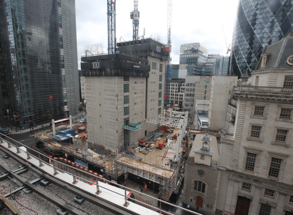
Fig 1.1 – Plan view of 100 Bishopsgate Project as at 0900 01/03/16
Structural Design
In my first few days the site engineer who was also involved in the full design process of this building kept saying the same two things to me, both of which will be familiar to PET (C) students after phase 1. These were 1) ‘It’s all about stiffness. Stiffness is everything’ and 2) ‘Follow the load path, it’s as simple as that’. I’m not convinced it’s quite that easy, but based on his advice and a vague memory of our lecturers saying something similar in class I thought it wise to spend the first week trying to increase my understanding of the way in which each structural element has been designed to behave, both in the short term temporary condition and in the long term permanent state. In the most basic description I can muster, this is as far as I have got:
Below ground level, two basement floor walls are supported laterally, in the temporary and permanent state, by concrete slabs (GL, BL1 and BL2) acting as permanent propping between a perimeter secant pile wall. Vertically, these slabs are supported by shear connections to steel plunge columns and additional reinforced concrete columns.
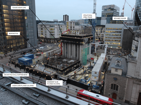
Fig 1.2 – Shear core progress imagery as at 1600 01/03/16
The Tower – Shear Core
Tower 1, as you would expect, is being constructed from a glass clad steel frame and composite concrete deck structure connected to a large central concrete shear core. This shear core, in the permanent state, is designed to carry roughly half of the Towers self-weight vertical load. It also transfers all of the high lateral wind loads (Max load of 32 MN in one pile) to ground through a series of very large reinforced concrete piles (Up to 1800mm dia) positioned directly under the core pile cap. They are therefore designed for the compressive and tensile forces resulting from combinations of self-weight and various wind loading conditions.
The Tower – Steel Frame
In addition to the shear core, the structural steel frame transfers self-weight load through large steel plunge columns located outside the shear core footprint or directly into large concrete piles outside the secant pile perimeter. The plunge columns have been cast into large diameter concrete piles (Up to 2400mm) that run to a depth of approximately 60m below ground level. This plunge column and pile system is designed to carry approximately half of the vertical load of the steel frame tower structure (Max load of 45.4 MN in each column), with the other half transferred down the shear core itself. Though the steel frame and plunge pile system provides additional lateral stability to the concrete core as it increases in height, in both the short term and long term condition all lateral wind loads are designed to be transferred through the core pile cap only.
In certain positions the design uses raked external columns that rise to a height of four floors. In the permanent state the load transferred from the self-weight of the completed tower induces a lateral, outward stress at the base of this column. In order to counteract this stress a large beam at ground floor level has been designed to resist these high temsile loads. The architects design (of course it does!) limits the size of the structural beam available, as a result specialist high tensile steel Gewi Bars have been selected to increase the tensile capacity of the concrete beam without increasing the amount of reinforcement bar required. With a quick google search I found 50mm Gewi Bars that can provide a yield capacity the region of 1MN each. There are 12 bars designed into the concrete beam and as a result are clearly critical beams behaviour in the permanent condition. At the moment there is an issue with resourcing these bars which has the potential to delay the critical path of this project by 7 weeks. This site runs at approximately £300k each week so the prospect of such a delay has got the Project Manager reasonably upset. I’ll cover this issue and my opinion on the project teams inital approach to mitigation in a more detailed subsequent blog.
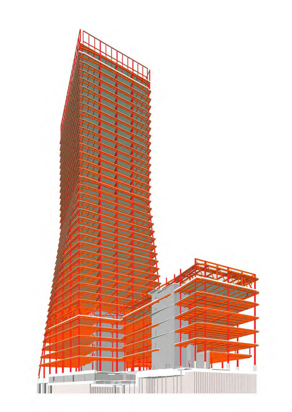
Fig 1.3 – Structural Frame Design
Podium and 15 St Helens Place
The Podium structure contains two smaller concrete shear cores surrounded by the same steel framed system used on the Tower. Over on the 15 St Helens site, a further two concrete shear cores will also be surrounded by a new steel frame and composite concrete deck structure. This new building will tie into an existing stone façade which must be retained in accordance with local conservation regulations. Currently this façade is restrained by a temporary steel frame structure on the front face. Other than self-load, this stone facade will not carry any additional vertical or lateral load imposed by the new steel frame structure emplaced behind it.
The Tower Load Path
The following diagram outlines my first attempt at a load path diagram for the tower component of the structure once complete. You’ll note I have indicated that the lower slabs are in compression from the total horizontal stress caused by the pore water pressure and effective stress behind the secant pile wall. The ground level slab on this diagram represents the position of the beam where the Gewi bars are required to provide increased tensile capacity.
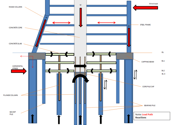
Fig 1.4 – Initial Load Path Analysis
Construction Method in General
The construction method of this project is a reasonably interesting aspect. Where resources allow, work on the three structures is being undertaken concurrently. In very general terms, my current understanding of the build sequence for the Tower component is as follows:
1. Secant Pile Wall and External Bearing Pile Installation
2. Perimeter Capping Beam
3. Internal bearing piles and plunge column installation
4. Excavation to BL1 (Exposing plunge columns)
5. Install Tower Crane 1
6. Commence Shear Core East Slip Form and St Helens Place foundation
8. Shear Core West and East Slip Form to level 6 – Install bracing steel work
9. Construct GL slab (Permanent Prop)
10. Emplace lower level steel frame (Minimum of five floors behind west core level)
11. Continue Shear Core to Level 10
12. Excavate to pile cap level
13. Construct 15 St Helens Place Steel Frame
14. Construct pile cap/BL2 slab (Permanent prop) and connect shear core concrete walls down to pile cap
15. Recommence core build beyond floor 10 and install BL2 concrete columns
16. Construct BL1 slab (permanent prop) and supporting columns
17. Install Tower Crane 2 and Tower Crane 3 (Both self-climbing cranes loaded onto the shear core)
18. Continue to Install structural steel frame for lower floors – Min of 5 floors between slip core and steel level
19. Install concrete decking – Min of 2 clear floors behind steel work
20. Install glass cladding on lower floors – Min of 8 floors below concrete decking
21. E&M fit out – Min of 4 floors behind façade cladding
22. Continue process to top out
This build programme involves top down and bottom up construction at the same time. It is designed to allow the structure on the lower levels to be completed, including fit out, as the building above it continues to rise to the point of top out.
At present state the site is excavated to BL1 and the concrete sub-contractor has started slip forming the west component of the main core. As soon as the Ground floor slab is in place (Gewi bar dependent) excavation of the basement will commence whilst the core continues to rise. Currently, the concrete core (East) up to level 6 is only supported vertically by a series of steel plunge columns that are cast below BL2 into large concrete piles. The bearing capacity of these steel plunge columns is designed for a maximum vertical load when the core is at floor 10, steel work is at floor 5 and concrete decking is at floor 1. Once the structure gets to this position these steel columns will be at the SLS design limit. Therefore construction of the lower basement concrete shear core and connection to the pile cap at BL3 is essential before further floors can be added beyond this point. As a result the progress of the concrete core upwards beyond level 10 (Critical path activity), is completely dependent on the top down construction of the basement levels.
As it stands there are a number of obvious issues which threaten delivery of the project along the critical path, I hope these will make good TMR submissions in the near future and I will try to update on how these are resolved and mitigated as the project team work through them.
