Archive
Back online! Blog No. 4.
I’m now back! After a reasonable period of time offline in the blogging world here is blog no 4.
My work has continued at breakneck speed along C620, hence the lack of blogs, and for those who can recollect blog 3 I had just finished the piling and had started the excavation of the foundations.
So here is a shopping list of what I have facilitated or directly completed over the last couple of months:
17 piling platforms excavated, backfilled and CBR tested.
170 PC RC piles, positioned, driven, tested and cut.
8 Steel H-Section piles, positioned, driven, tested and cut.
28 permits to dig completed.
Excavations set out.
1000m3+ of material excavated.
Heights checked.
22 service ducts and water mains positioned, excavated and placed.
136m3 of blinding poured.
Heights checked.
170 PC RC piles marked and cropped to expose rebar.
8 Steel H-Sections cut and modified for a deep foundation in tension.
Over 200m3 of groundwater pumped out of excavations.
Over 200 nails positioned for setting out.
Reinforcement steel fixed, positioned and checked against RC drawings.
Heights checked.
56 earthing cables set out and welded.
Over 1kM of shuttering placed.
Height, vertical and horizontal cover checked.
Foundations blown out.
69 individual bolt pads positioned.
Heights checked.
500m+ of chamfer filet set.
Heights checked.
11 notification to pour forms completed.
581m3 of C32/40 concrete poured.
60 sets of cubes taken.
Heights checked.
Shuttering struck.
Excavations backfilled.
1 large QA folder still to be completed!
The last base was poured today and I now have over a week’s worth of QA paperwork to complete for the whole section. 3 of the steel trestles have been constructed onto the early bases and they all fitted perfectly onto the bolt pads – so far, so good – fingers crossed for the rest!
So what have I learnt? Loads of stuff! But for now ill conclude the piling episode with a few remarks as I know those who followed my previous episodes cannot wait for the conclusion?!
As you will remember many PC RC piles broke, steel H-Sections were used as replacements. This was the focus of TMR1 and as some of you won’t be lucky enough to read that particular gem so I will expand on my observations.
Risk.
The risk within the piling sub contract was shared reasonably effectively between Graham Construction and Balfour Beatty Ground Engineering (BBGE) and reads ‘‘The subcontractor has not allowed for overcoming man-made or naturally occurring obstructions (whether they are below ground, surface or overhead) which impede, or deflect the Works, or result in them failing to achieve the design and/or specification requirements. Any additional time and costs associated with overcoming or attempting to overcome such conditions (including but not limited to set ups, displaced and/or damaged works, replacement and/or additional works, lost consumables, and damaged plant) shall be in variation. The subcontractor however has allowed for the cost of 30 replacement piles on this occasion. Any further replacements will be a variation in accordance with this clause. Should less than 30 replacements be used the cost saving shall be shared by both parties’. This figure of 30 piles was agreed by negotiation as initially BBGE would only accept 10 breakages as part of their standard contract. It still proved an underestimation as these replacements had been consumed during the first stages of the operation whilst piling for the RC storage silos. Subsequent replacements were charge at the agreed original pile cost calculated by the length required: 18m and below at £450 per pile, 18m and above £620 and driven via a variation order. All the piles for C620 were 18m and above and therefore the replacements were charged at £620 per pile with the additional cost of pile testing at £120 per pile (1 in 10 tested). This risk of breakages had been identified by the Graham design team from studying the borehole data and hence the 30 pile float had been negotiated. This risk and associated cost was covered by Graham Construction.
However BBGE also took a risk within the contract. The calculations conducted by BBGE detailed the design depth for the piles to achieve the specified working loads across the various areas of the site; the price was quoted from these calculations. However the piles were installed to a dynamic resistance, or set, calculated using the Hylie formula (less than 25mm per 10 blows) and therefore the actual length varied from those suggested by the static calculation. The additional sections required to achieve the extra depth and set, beyond the calculated and quoted for depth, were at a cost to BBGE. In addition, BBGE priced the contract on the number of piles driven at the calculated length, not on site time. The re-organisation of the piling during and after the breakages resulted in an amount of standing time charged at a set rate, higher for the first hour and then reducing for subsequent hours. This time whilst at a cost to Graham, was at a greater cost to BBGE as the greater profit for them is in the driving of piles succinctly and quickly. Whilst the rigs are standing the BBGE profit is reducing and it also delays the rigs from moving on to other sites where the more profitable piling can continue. When looking at the number of breakages across the whole site coupled with the additional lengths required on a significant number of occasions, it is quite possible to envisage a reduced profit margin for BBGE.
I feel that the risk was actually well shared by both parties. On the surface it appears that the majority of the risk was held by Graham with the low number of potential breakages (30) written into the contract but on closer inspection of the ground investigation data it was clear that deeper piles would likely be required and hence a risk to BBGE.
Ground Investigation.
A large amount of ground investigation data was available to both the designers (HBPW) and BBGE as the pile designers from a series of surveys conducted at various times across the site from when it was reclaimed from the sea in the 1990’s. From the vast amount of data available BBGE took the unusal step of not using a design borehole to design the piles but used the actual borehole data. Whilst not particularly risky the boreholes used where not, in my opinion, the ‘worst case’ boreholes that in my logical mind would choose. In addition not all of the data was referenced by the main designers for BBGE to use to design the piles and this missing data contained the worst case boreholes, including the one closest to the area where I broke all the piles that had a 2m deep layer of chalk made ground. Has all the information been thoroughly considered it is likely that the piles may have been redesigned at a deeper depth, costing BBGE less and invariably saving on the number of breakages. This in turn would have led to a reduced cost to Graham and the steel section solution being reached earlier, if not from the outset.
The ground is a risk. The importance of GI cannot be underestimated and whilst in this case the problems were not from the lack of information, as is often the case, but from a lack of exploitation of the available data.
Apologies for the long blog and the lack of pictures. My iphone slipped out of my pocket on Thurs afternoon, and as is always the case with sods law, got immediately run over by a dumper with all my exciting photos. Happy with that.
Conveyor 620 continues.
Blog No.3
My work continues along conveyor 620 and I am now following a fairly set process to complete the different foundations.
My last blog concluded with the piling almost complete (6x steel still to be driven) and preparation for the next stage of the foundation construction. So if I explain what I have done for Transfer Tower (TT)615 the process for all the other bases is more or less the same.
So initially I set the pile cut off point at 50mm (cover) below the finished top of concrete (TOC) level and cut the piles.
By extrapolating the information from the foundation GA drawing I set the level of the shallowest element (the 300mm main slab) included 50mm for the blinding, and excavated the entire base to that depth. This included 800mm of additional horizontal space around the outer edges for the shuttering to be subsequently placed. Once this initial excavation depth had been dug I then set out the slab ground beam locations and services that required further excavation (usually 500mm – 1000mm depth from TOC) , again including 50mm for the blinding. Once excavated the bases look something like this.
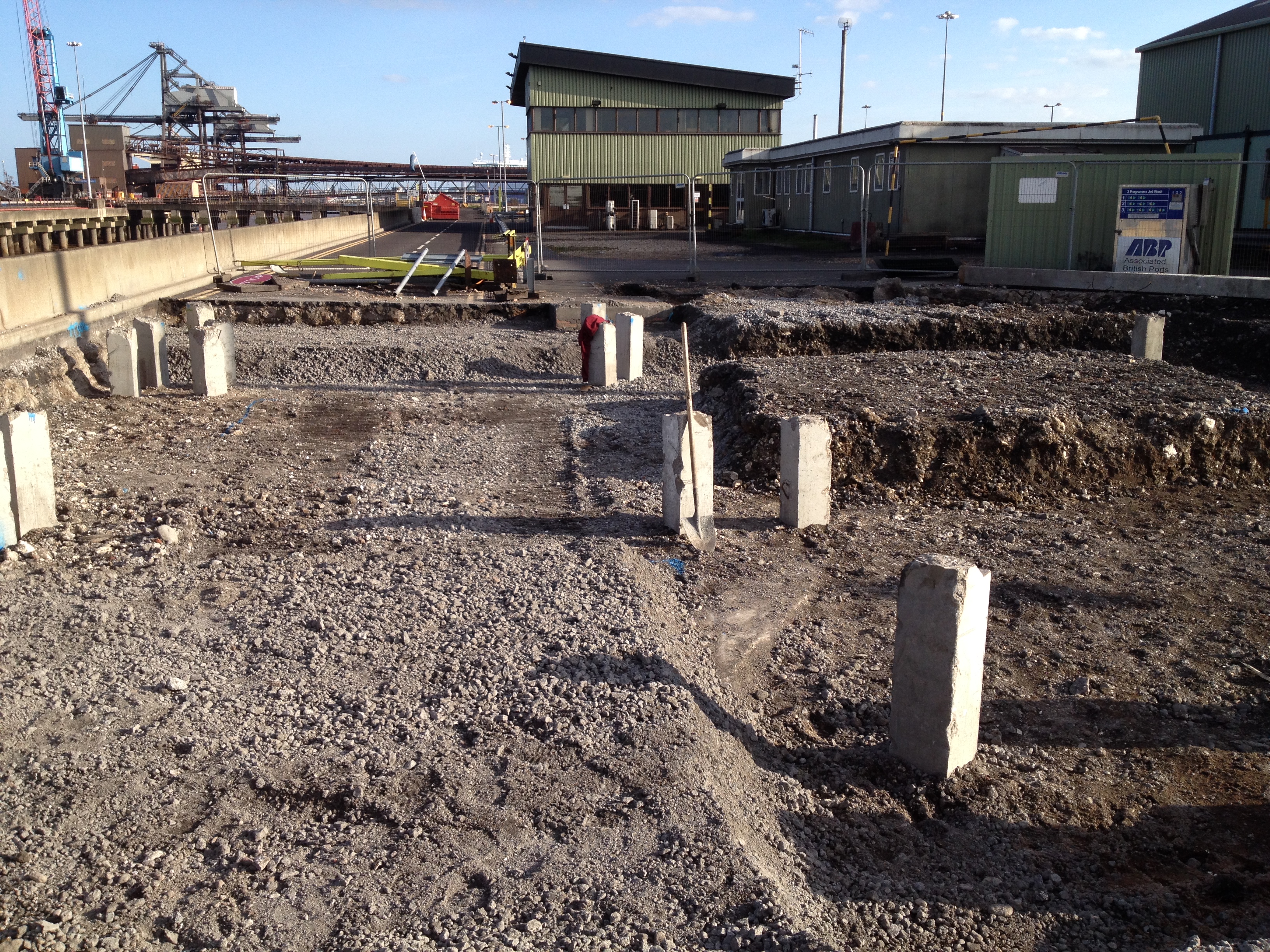
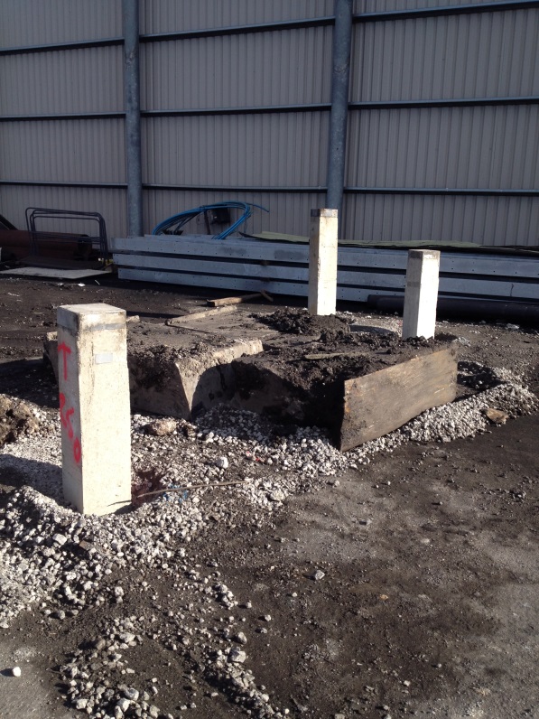
TT535 piles cut 50mm below TOC, excavation complete for slabs and beams.
I then cubed up the foundation, ordered and placed the 50mm blinding layer. Semi dry concrete was used to grade the slopes from the ground beams to the slab locations.
Once the blinding cured I set the level for the piles to be crunched and the steel exposed (usually 75mm above the blinding as the bottom cover is 75mm) and the rebar was then broken out. Once the steel was exposed the electrical subcontractor came in and placed all the earthing cables, welded to the pile rebar.
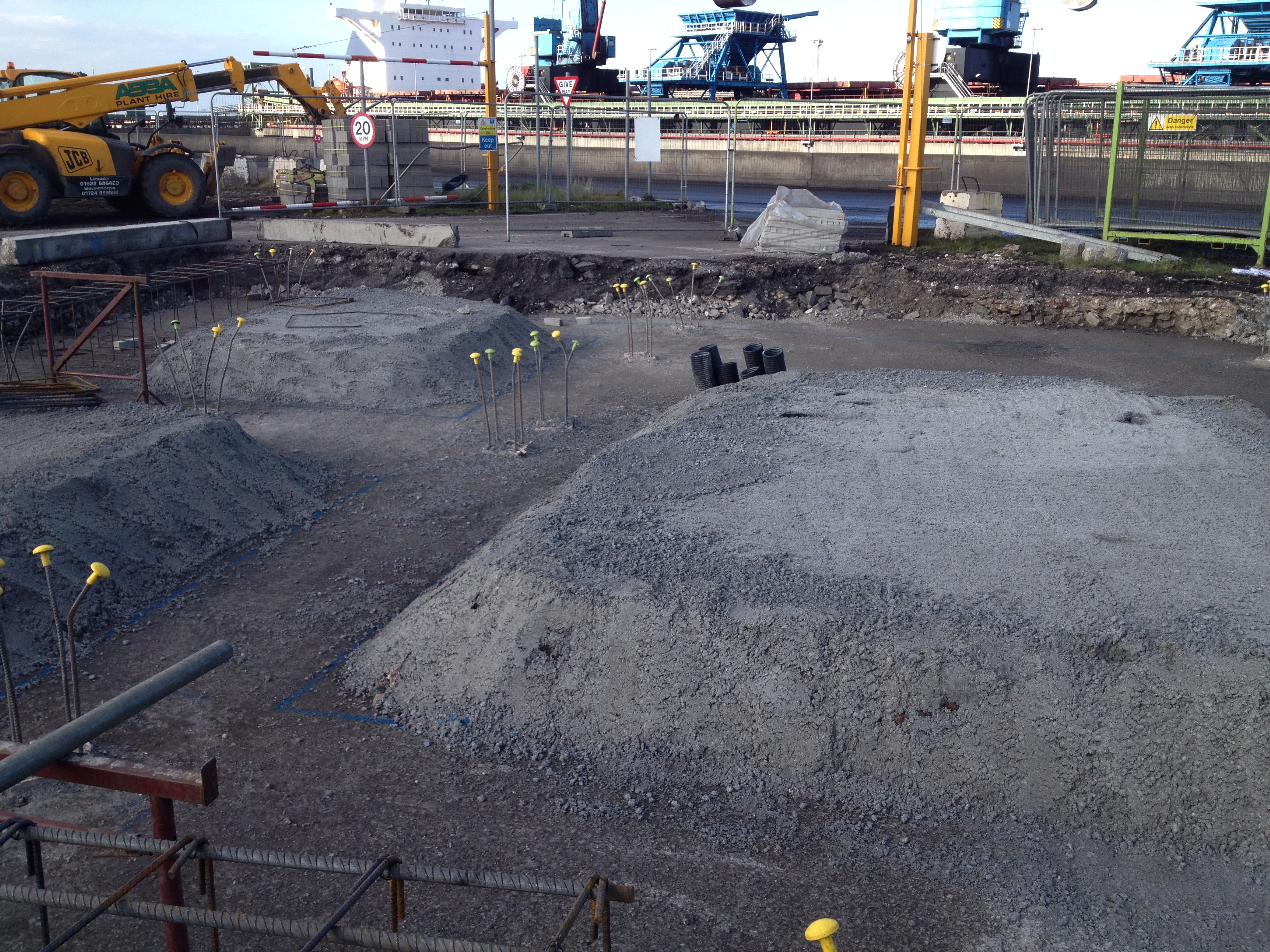
TT615 service pipes placed, blinding poured, slopes graded, piles crunched to expose rebar.
Using a total station I set out the extremities of the foundation, placed the nails, strung out the edges and sprayed the lines for the steel fixers.
The fixers then arrived and started positioning the steel reinforcing and I was checking the configuration, cover and heights.
The joiners placed the shuttering around the steel and again I checked the alignment and cover. Once the main body of the steel was completed I set out the positions for the starter bars for the various upstands and walls that come out of the foundation. These starter bars still need to be placed and the next stage will be to place the bolts for the structural steel, prior to pouring.
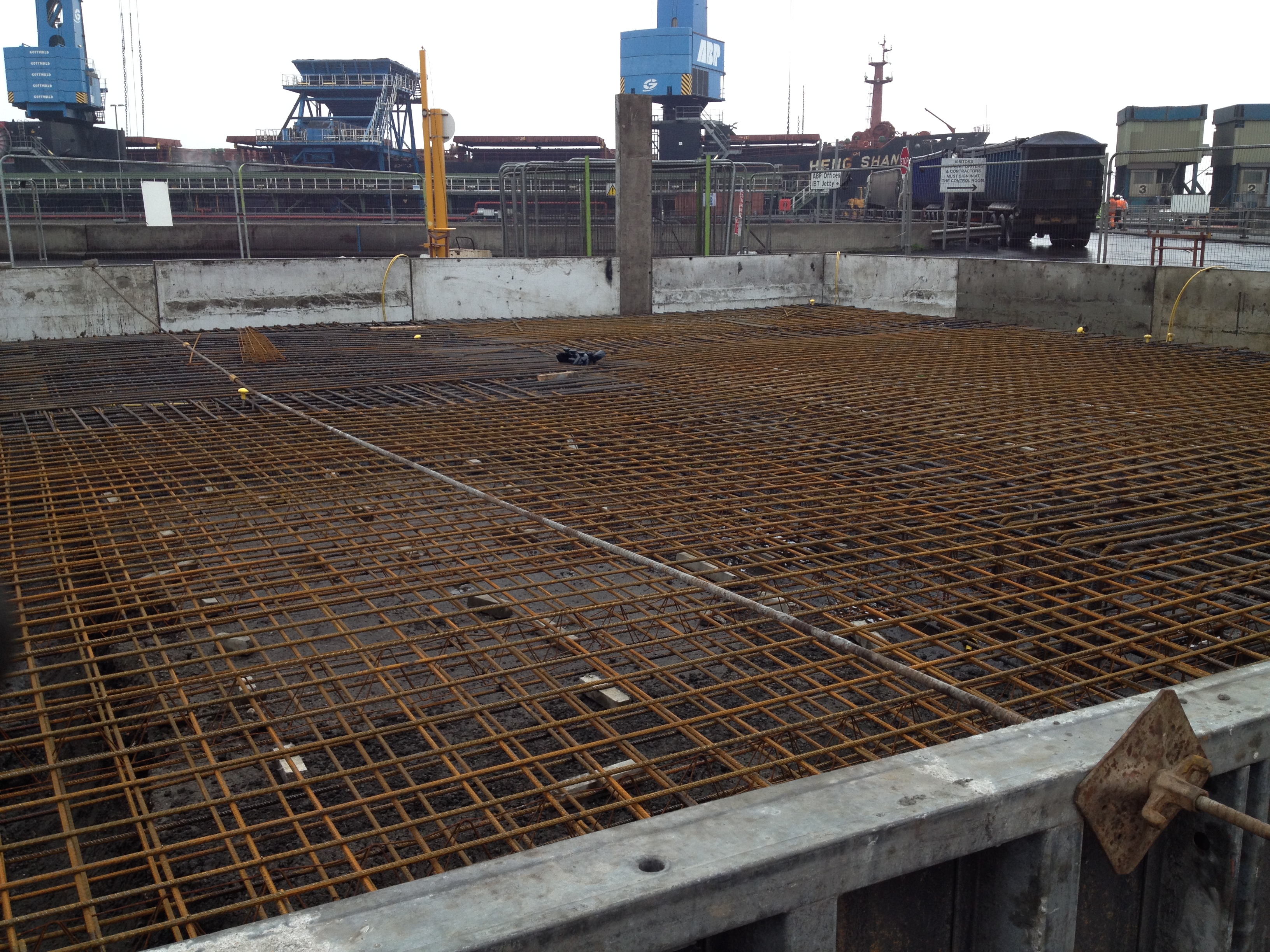
TT615 steel and shuttering in place. Starter bar locations for upstands and walls marked out.
This was the process I conducted for TT615. TT535 is awaiting the steel fixers and I am overseeing the excavation of Trestle 2-4 and the GTU as I write. It’s now a case of keeping the process up and ensuring I am 1-2 days ahead of the various teams of labourers, fixers and joiners spread across my section of work.
Reflections.
Services. The drawings do not include all of the services that may need to go into the foundation. I have only been caught short once where 6 service ducts needed to be placed into one of the bases and were not included in the GA. Luckily this did not require much remedial action and I discovered the omission before the blinding was poured (just). I did lose one of the smaller pads I had left for the construction of the slabs as the services went through it, but the fixers managed to make some steel chairs to support the slab steel as it was only a small area. Cleary this has a small cost implication as the ‘void’ will now have to be filled with structural concrete but as we are talking probably 1m3 I’m sure it will not be a problem when we come to pour.
Even when I found the drawing for the service ducts and was about to start the excavation I double checked with the electrical sub-contractor that it was in the right place. He agreed it was coming through the slab in the right place but the proposed alignment was incorrect. He then produced version A of the GA drawing (I was on G) and asked me to realign the proposed route as the electrical services had been designed to his drawing. On this occasion it did not significantly alter things but apparently this has happened on several occasions, with different drawing versions creating confusion and additional work. I now ensure that I communicate with all the service stakeholders prior to any excavation.
Speed and Accuracy. It surprised me just how quickly on completion of the blinding the steel fixers were all over the first base I had prepared. Having managed to place the blinding a day ahead of schedule I thought I had bought myself a little breathing time but I think everyone else thought the same. I set the nails and sprayed the extremities of the foundation and the fixers were on the slab before the paint was dry! I had a concern about 2 of the points appearing to be not quite square (on confirmation of the positions with a tape) and so queried the off sets on the GA. By the time the error was confirmed and I had the opportunity to re-shoot the positions the steel had been placed and the shuttering was being positioned. I spoke to the foreman in charge of the joiners and pointed out the adjustment required but as a couple of the holes for the shuttering had already been drilled in the blinding they simply ignored the new position and cracked on anyway.
Shuttering and steel out of position.
This left an approx 30mm extension in the base. I was not overly concerned as the cover was still sufficient, the alignment still straight and the edge did not tie into another structure. I highlighted the issue to the section manager who agreed with me and did not see it as an issue. What did surprise me was the lack of care shown by the joiners. The issue was highlighted in good time for them to only have to conduct 5-10mins remedial work. By the time the section manager had seen it, if he had decided that it needed changing the amount of remedial work required had significantly increased as all the shuttering was in place. Perhaps the joiners experience led them to know what would need changing and what wouldn’t but I’m not sure they have ever heard of the phrase ‘a stitch in time saves nine’. The experience has led me to be extra cautious when studying the GA’s. In this case it was difficult to see the error prior to them being set out and due to the speed of the follow up activities after marking out the foundation it proved difficult to actually prevent the subsequent errors. It subsequently took me half a day to set out the dozen or so nails for TT535 as I wanted to be 100% confident in the positioning after this experience.
Responsibility. The original section manager I was working to has moved to another site. This has prompted a reshuffle in the section, where the previous section engineer has moved up to section manager and one of the site engineers has moved up to section engineer. That has left 2 site engineers responsible for all the work across the site (bar the silos). Last week the other site engineer was covering a night shift as the steel subcontractor is significantly behind schedule and having to make up the time. This quickly left me as the only engineer in the section and although the section engineer was mucking in I found a lot of extra work on my plate and have now been overseeing the construction of another substation that I may blog about in the future.
It has been several weeks since my first blog but in that time I have been on a steep learning curve and very busy.
Most of what I am about to mention I had actually written in a draft blog but I failed to finalise and publish it before the writing of AER 1. To be fair most of what I did draft went into AER 1 so if you’re likely to read AER 1, I wouldn’t bother continuing from this point!
After my first real on site experience with the rail load out silo steel roof I quickly graduated from working as a site engineers assistant to being given a section of work to really get my teeth into. As such I have spent the last 3 weeks piling and resolving the 535, 615, Trestle (T) 2,3,4,5,6,7,8,9,10 and C620 Gravity Take Up Conveyor 620 (GTU C620). It is proving to be a great opportunity as I various issues that has thrown up.
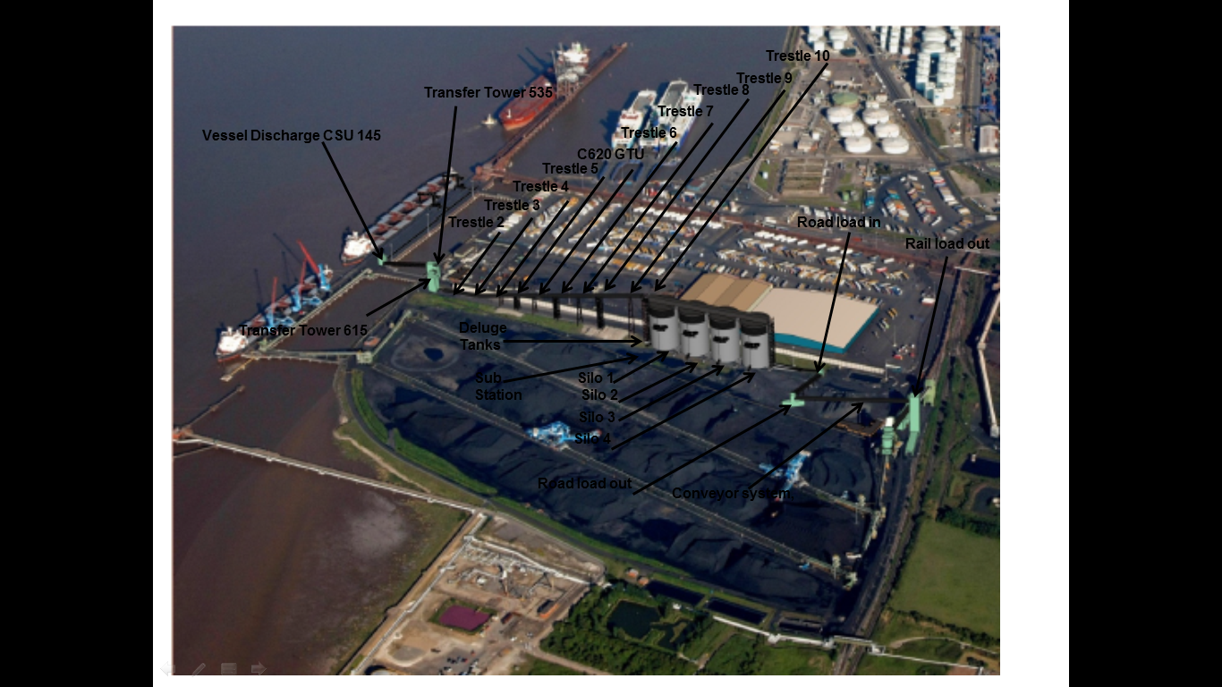
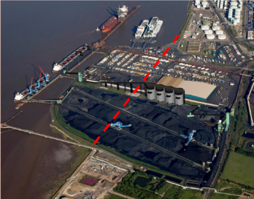
The following picture I prepared for AER 1 and highlights the area of the site I will be working on, effectively Transfer Tower (TT) am now able to work on this element of the project from the ground upwards and see the entire element through from clearance of the site to turning the conveyors on.
The first part of the work has been driving 163 x 27m (13m and 14m sections) 0.27m2 pre-cast RC displacement piles for the foundations of all the previously mentioned elements of the section. To start I was using the GPS equipment to mark out the extremities of the piling area for the plant to break out and prepare a suitable surface. This involves breaking through the 400mm concrete slab that was previously one of the main routes in and out of the complex for the HGVs (hence the thickness), clearing it away, backfilling with a suitable aggregate and compacting. Once the area had been prepared I marked out the exact locations of the piles for the rig to drive them through the next day. I was working 1-2 days ahead of the piling rig to ensure that it was continually piling, trying to minimise the amount of expensive standing time. All Royal Engineer Troop Commander bread and butter stuff up to that stage.
The main issue I had was pile refusal and breakages.
There were 25 breakages, 10 refusals and 2 where the final rake was too large and therefore required replacing. These issues were largely in a couple of the foundation bases.
From the surface it is difficult to establish whether the pile is broken or not and I naturally questioned what the driver was telling me when they started to break one after another. To that end I sat in the cab, with the driver, to see the breakages for myself. The driver was under the impression that the piles were breaking at around 5-8m. Once in the cab it was clear to see that obstructions were being encountered at about 5m due to the number of blows per 0.25m driven length significantly increasing (30-50 where normally 5-20, 5T hammer, 250mm drop) and this would continue through till approx. 8m. This band was where the breaks were suspected to be occurring as the piles were ‘kicking away’ from the driven course. This could be proven when compared to the penetration record of successfully driven piles where an increased stiffness (significantly increased blow count 50 -100) was seen at around 20m+ demonstrating that the toe of the pile had reached the correct depth. If the pile had broken around 5-8m this increased stiffness was not encountered as the upper section would shear off from the lower and simply slide passed it, thus not achieving the correct depth. This was not always the case but as a general rule it indicated a broken pile.
The procedure for a broken pile was initially simple as I would contact the designer with either a recommended location (predicted from the broken pile and 2D off set estimation) or request new co-ordinates. Within a few hours I would receive a confirmed new location to re-plot and drive. At times this new location would drive successfully but not as a general rule. A few of the piles in a couple of the trestle bases required 3 or even 4 replacement positions and the pads were extended in 2 directions to accommodate the new positions. In fact the increased slab dimensions negated the requirement for 6 piles in one location, reducing it to 5, due to the increased capacity of the shallow foundation. On 2 of the pads I decided to stop driving the piles due to the fact that any viable solution was becoming more difficult with the area quickly becoming an underground forest of RC.
The nearest borehole sample I could find was from approx. 100m away and confirmed this obstacle belt of made ground to a depth of 7.4m which included chunks of RC, railway sleepers and large rubber fenders!
3 x rubber fenders dug out at 3M!
Various solutions were discussed from deep excavations to drilling and eventually the use of steel H-section piles. We managed to ‘find’ a 9.5m 206x206mm steel section to use as probe and drove it right through the middle of the most troublesome base. For my part this was a confidence boosting moment as a number of the management watched the pile being driven (having not been completely content with the number of piles breaking) and it demonstrated behaviour exactly as I had been describing. The number of blows increased at 4m as it entered the obstructions and the pile virtually stopped dead at 6m requiring an increased hammer drop of 850mm to persuade it through the obstruction. This it did and after 8m the number of blows reduced significantly as it had driven through the obstruction and continued normally.
I spent all day Monday consolidating all the paperwork and sending all the info (including the steel results) to the designers for a redesign of 2 of the foundations where a total of 6 piles still require to be driven. I await the outcome and if I have time I will have a bash myself to compare to the actual design that comes back – all good TMR 1 stuff. However things move apace and today we received the RC details for TT535 and 615, so the steel has been ordered and I have been back out marking pile cut off points for crunching and the base ground beam positions for excavation and blinding by the end of the week. As I type this the section manager has just handed me the remaining RC details for the trestle bases – no rest for the wicked.
Blog time.
Graham Construction are currently undertaking the design and construction of a renewable fuels terminal for Associated British Ports’ (ABP) in sunny Immingham. The port facility will give ABP the capability to import, store and onward transfer wood pellets primarily to the Selby based Drax power station , as they transform 3 of their 6 coal-fired power generating units to biomass fuelled units.
Once completed, the 11.5-acre facility will be a fully automated bulk-handling terminal that will handle biomass for the region’s power generating industry. The terminal will have the capability of handling around three million tonnes each year, and be able to store up to 100,000 tonnes of wood pellets. Four storage silos will have a total capacity of 168,000m3; equivalent to over 60 Olympic-sized swimming pools. The design and construction project comprises:
• Provision of continuous ship unloaders for offloading the wood pellets from ships
• Conveyor systems – circa 1.2km of conveyors
• Storage facilities – capable of storing 100,000 tonnes of wood pellets
• Road vehicle loading facility
• Rail load-out facility
• Extensive safety systems required to ensure safe handling of wood pellets
The Graham team includes Ramboll, local consultant HBPW Consulting; materials handling contractors Whitwick Engineering; and local electrical firm Lectec Services.
In essence the wood pellets are taken from the ships and placed onto a conveyor system that fills the large silos from the top for storage. When needed they are vibrated through a central hopper onto another conveyor system running underneath the silos in a tunnel to the lorry or rail load out point as required.
The four main silo walls had been completed prior to my arrival with the Graham team working 24hr shifts from 07 Nov – 11 Dec 13, fixing 2400tonnes of rebar into place and pouring 10800m3of concrete during the slipform process. The 56m high, 36.5m diameter silos were poured utilising 2 sets of slipform equipment to maintain the construction speed of around 3m per 12 hour period.
This week has seen the silo section completing an as built survey at the top to ascertain the position of the bolts for the fabrication of the steel roof trusses and conveyor systems that will be craned into place in the spring. The floors of the silos are currently being graded to a slope of 10degrees towards the central hopper that drops the pellets down onto the conveyor system in the central tunnel running underneath the length of the silos. These floors will then have a 300mm slab cast on top and vibrating panels constructed to move the pellets.
The foundations and slabs are already in place for much of the conveyor system from the silos to the rail load out point and the steel superstructure is being erected.
In addition the smaller load out silo over the rail head itself has also been completed and it is being capped by a 37t steel cupola lifted by a 1000t crane this morning.
On arrival I was allocated to the silo section but after a quick rethink by the project manager I was reallocated to the section responsible for ‘everything else’, as that is where the majority of the work now sits. To that end I have been working with one of the site engineers on a number of tasks from setting out of various foundations, formwork and services to preparation of the previously mentioned steel cupola. After a couple of weeks to get my head around the site the Section Manager is going to put me in charge of a section, likely to be the piling and slab foundation construction for the conveyor system from the quayside to the large silos. Can’t wait.
One observation that I have made immediately is the lack of preparation that has occurred prior to the lifting of this steel cupola. The rail load out silo was completed some time ago (slip form video at the following link https://www.youtube.com/watch?v=0_EehR17JVg), with the initial bolt layout for the steel cupola being set into the structure along its 0.45m top ring. Once complete, the as-built survey was conducted and the steel designers noticed that the bolts were 120degrees out of position. The bolts were cut out where required and new ones drilled and grouted into position followed by another as-built survey. This data was sent to the fabricators who built the steel structure and assembled it on site. Once constructed, measurements were taken between the bolt holes in the column base plates of the cupola and checked with the bolts on the top of the silo and they still did not match. This was noticed some time ago but came to a head on Tuesday when the very expensive 1000t crane turned up to lift it into position. A significant amount of standing around and head scratching resulted in nothing being done. The high winds on Tue – Thu resulted in the crane being sat idle until a window presented itself to manage the lift (this morning). On the weds I went up with the Section Engineer to take some further measurements, to again confirm that the bolts would not line up with the column base plate holes, and when I was up there I was astonished to see that there were bolts everywhere. Not all of the previous bolts had been removed and as we moved around to take the measurements the Section Engineer had to continually check which bolts were the ones that were to be used. It was also quite clear that the scaffolding hand rail for the walkway on the inside on the silo was protruding past the silo edge and the cupola would not be able to drop down past it without catching.
In my mind the bad weather provided an ideal opportunity to prepare everything for the lift to be as smooth as possible in what would likely be a small lift window. This would also reduce the risk of a failed lift and potentially greater cost to Graham as the crane would have to be rehired for another day. I suggested simple things to the Section Engineer such as spraying the bolts that were to be used for easier identification on the lift day, measuring the scaffolding handrail and adjusting it as required and removing the unrequired bolts prior to the lift. As the new kid on the block, not responsible for anything to do with the lift, I did not push any of these points again…
The lift happened this morning . Problem No1. The cupola would not drop past the scaffolding handrail. Queue frantic stripping out of the scaffolding handrail. Problem No2. The plate holes would not position over the bolts due to the unrequired bolts. Queue frantic action with the grinder to remove unwanted bolts. Problem No3. Only 5 of the 22 column plates actually fitted over the bolts correctly. Queue frantic hole enlarging and plate cutting of the remaining plates. The lift was completed and it took 6 hours. A bit of simple foresight and preparation could have reduced the whole operation to at least half that time reducing the risk of a failed lift. The weather is now howling once again and it has been completed literally at the last safe moment. No cuff too tuff I suppose?
On reflection I’m not trying to pat myself on the back for making some very simple observations, that should have been made, but it has surprised me how little thought goes into the conduct of reasonably significant costly procedures. In defence of the operation the surveying on the top of the silos is very difficult at best. The working platforms are 50m up on the inside of the silos and the initial location positions are shot from the ground in almost continuously high winds, making setting out and surveying extremely difficult. In addition, apart from the obvious preparation issues that I have mentioned, I think the design is fundamentally flawed. The bolts along the top edge of the silo are fixed into position, meaning there is absolutely no play in the positioning of the cupola column plates that could have taken up the small surveying errors. I have asked on several occasions why the bolts are cast in situ like this and not placed into cones as every other column foundation on this site is, but have just been told ‘that was the design’. A cone would seem all the more pertinent as the designers forecast an element of outward deflection of the cupola during the lift meaning the column plates would naturally flex past the fixed bolts. There is ample space along the 0.45m rim for the cones but the same design has been used for the larger silos and I foresee the same problems come the time for their roof structures to be lifted into position.
That’s all I have for this week.
