Archive
Bouncy Bridge
Good news! If you are a person who takes to train to Luton airport and have to deal with the shuttle bus to the airport terminal, worry no more. The owners of the airport have realised that the fact you need to take a bus to the terminal is putting off people travelling to their lovely airport and are doing something about it.
Arup have been working on the design for an automatic shuttle system (MPT – Mass Public Transit); think North to South Terminal at Gatwick Airport. Which will whisk you from the National rail platform up an escalator to a footbridge and into the Airport terminal in 4 minutes.
You may have seen an article in the press/ NCE magazine.
https://www.newcivilengineer.com/latest/115m-luton-airport-rail-link-tender-out/10017758.article
https://www.newcivilengineer.com/latest/details-revealed-for-luton-gateway-bridge/10017973.article
Network Rail Footbridge
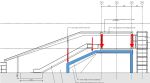
As part of this project, over the last 3 weeks I have been working on the design of a steel footbridge structure which will span over the rail tracks at Luton Parkway Station. The bridge will connect into two lifts (which are self-supporting) and five escalators supported by bridge superstructure.


The bridge itself is a continuous steel vierendeel truss (I had to look into vierendeel trusses to realise that a vierendeel truss isn’t actually a truss, but this point is probably for another blog). The bridge is supported on three pairs of portal frames that sit on the station platform supported by piled foundations. All sections are welded rectangular steel sections. The shape of the portal frame is unconventional and is driven by the architects to maintain as much clear space under the bridge to increase sightlines. It is this shape which is starting to cause problems.
There a number of loads and combinations acting on the portal frames however the main variable loads are from the bridge and the escalators. Which act to destabilise the portal frame. Its easy to realise that the shape isnt the best for a portal frame. As the frame is loaded at mid-span the horizontal members want to straighten an overturning moment is generated to topple over the tallest column.
-
- Main Variable Actions on the Portal Frame
-
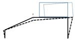
- Deflection of the Portal Frame
3D modelling
I have generated a model of the bridge in GSA (design programme written by Arup) to compare against my hand calcs and to model the 3D element of the structure. the age old problem of whether to model the frame with pin supports or moment connections raised its ugly head.
Modelled with pin supports deflections at the top of the escalator are about 40mm. Although no one can tell me what the allowable deflection for an escalator is I am assuming this this is too high. Does anyone have any experience with deflection in escalators? If I fix the column supports I can reduce the deflection to what I think is a more manageable 15mm however this generates a 2MNm moment which needs to be restrained. Meanwhile, I am looking to shorten the span from 18m though this requires negotiation with the architects.
Dynamic modelling
Arup’s experience with ‘bouncy bridges’ is quite developed following from history that people are happy to talk about. Arup are responsible for the millennium bridge fiasco though I am reliably informed by tony that the engineer responsible no longer work with Arup and works at Tony’s placement.
The dynamic response of bridges has been an interesting learning curve. Eurocode 1991-1-4 states that if the wind response frequency is above 1Hz then a dynamic check need to be conducted anyway. I have conducted a dynamic analysis of 10 modes which only considers the dead and superimposed dead loads. Unfortunately most modes have frequency between 2Hz and 7.5Hz, which puts it at risk of user induced oscillations.
These are videos of two of the dynamic modes of failure. In both the deflections are severely exaggerated but they are interesting and show the movement. You can also see that the deflection is largely as a result of the portal frame. Hopefully the videos work.
The second largest movement is due to the articulation of the bridge. The bridge is fixed to the portal frame at the centre on a pin bearing which means that all lateral forces are resisted in a rather small portal frame (2.75m wide) acting in the minor axis of the section.
Next Step
The design is still developing so there is still further to go. I initially left out the floor plate from the model as I wanted to be conservative. However by including it should stiffen up the lateral movement. I have also arranged a meeting with the architects to see how we can reduce the span or even the angle of the portal frame.
Watch this space.
Site Update, many activities
No major problems on site but I thought that a more general site update might be due (especially in light of a potential placement for next year).
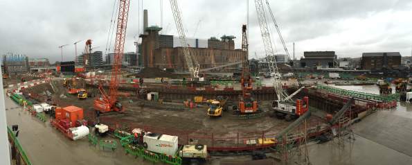
Recently in the last few weeks the activity has steadily increased as the TBM parts have been delivered on site and the SCL (spray concrete lining) team are setting up. Many robotic tracked vehicles driving around. This has all come as the primary works in the Crossover box come to an end. Construction of the box is as far as it will go until the TBMs have finished tunnelling. So there is a oncoming shift in focus of the main civils team from the Crossover Box to the Station Box. The work force on site has also ballooned 3 times what it has been for the last year.
Crossover Box
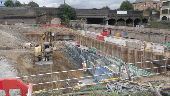
Excavation. The excavation has now been completed. All the props strain gauges are showing that they are behaving as they are expected and shape arrays in the d-walls are showing expected deflection. Now that the excavation has finished the monitoring will be reduced and shape arrays and relocated to the Station Box.
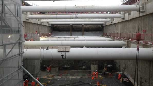
Crossover Box from B-02 level
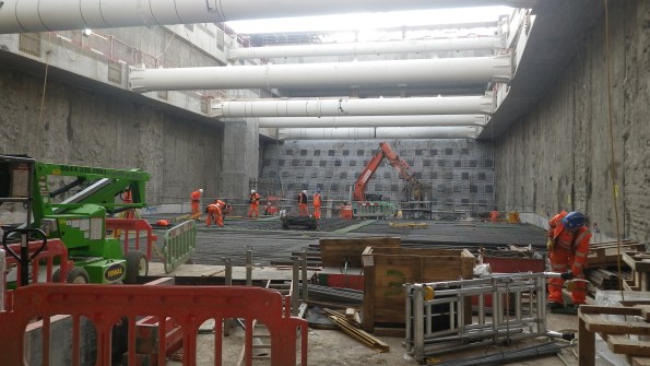
Crossover Box from B-04 level
Soil Nailing. The last of the excavation has been possible due to the soil nailing. Over the last week BAM Nuttal has been sub contracted to install six rows of soil nails to stabilise the clay at a 70° slope. This required 24hr working to excavate 1.2m high benches into the clay at night, so that nailing could take place during the day. This is a semi-temporary condition, for up to a year. The London Clay was holding well, but for how long… no one knows squared.
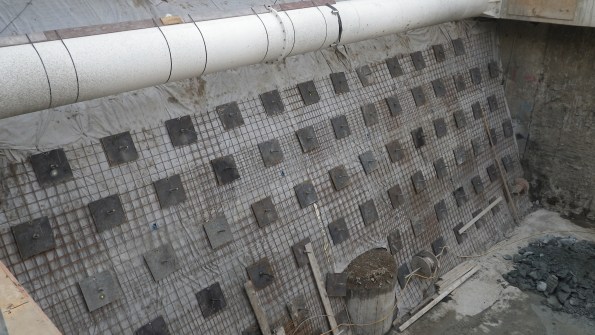
6 rows of soil nails
Base Slab. A third of the base slab (pour 1 & 2) 1.5m deep, has been completed with the middle third pour (pours 3 and 4) planned for Thursday. This has gone largely without incident… surprisingly.
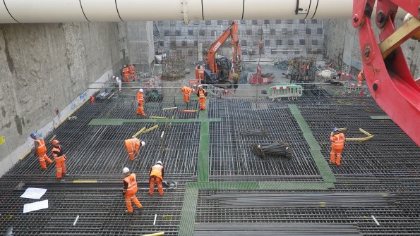
Steel fixing base slab pour 3 and 4.
Headwalls. The stage 1 headwalls are being cast today. They are essentially columns cast against the d-wall. These increase the stiffness of the box and provide additional load capacity to allow two 6m diameter holes to be removed via stitch drilling. The headwalls are 6.7m high and are being poured through guillotines in the formwork under pressure. This has required a lot of planning, much more than usual. It’s the first time such a high pour has been done for most on site, its going smoothly so far.

Temporary Bridge. In addition DAM structures are about to finish the erecting of a steel bridge over part of the primary structure. This will provide access across the site once the excavation has started on the station box side. The steel has just been finished. The RC deck is not being constructed (you can see some of the falsework in place at the far side.
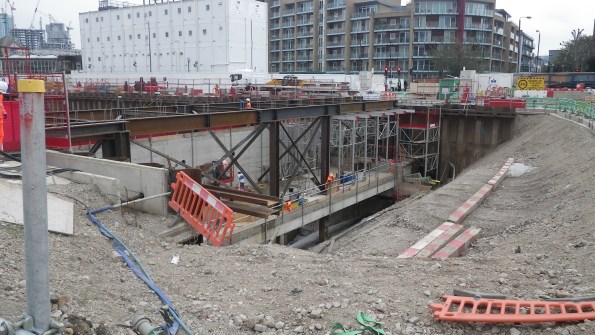
Steel Bridge complete – RC deck under construction
Station Box
Piling and D-walling. Rotary bored piles have 5 weeks left on site which will provide quite a bit of relief as the ancillaries (casings, augers etc) for 4 sizes of piles and the polymer plant are de-mobilised.
D-wall panels are currently 39% complete. This is a delay of 4 weeks so as to reduce the impact to the FLO works, my time has been largely taken up negotiating a phased handover ahead of the completion. As expected this is highly contentious. Lots of commercial discussions but we now have a solution that should keep FLO on their programme to built target and CSL with enough room to actually complete the piles.
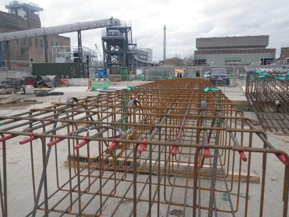
Capping Beam Construction. Lastly, following the handover of the first 4 gridlines (24m long) FLO have started to break down the d-walls and have started the construction of the capping beam.
First section of Station Box Capping Beam.
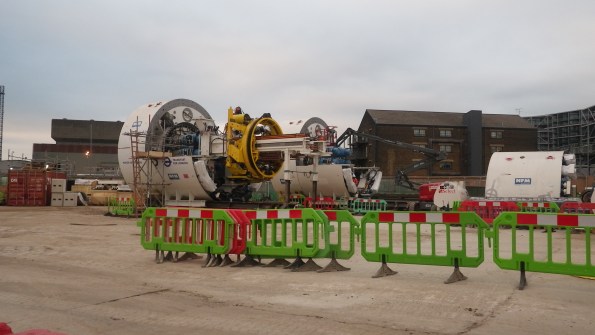
Semi assembled TBMs
“Erm, the Grab is stuck!”
I was in the process on drafting a general update on the progress on site but late on Friday the piling sub-contractor’s world started caving in and it dragged me in. On Friday at 1900 (perfect timing like all great catastrophes) I, with the Project managers for FLO and Cementation Skanska were scratching our helmets, one of the diaphragm wall grabs was stuck at 60m. The situation worked itself out in the end but at the time, all options seemed bleak.
The background
The grab first got stuck at a depth of 60.5m depth around 1300. This meant it had 0.5m left to dig before the sub contractor long weekend. Either before or in the process of trying to release the grab, the rig had a hydraulic failure and lost 50 litres of hydraulic fluid. At this point it was hoped that the hydraulic failure was the reason it was stuck.
Unfortunately after the endless calls to Germany, diagnostic and repair the grab was still stuck. Shock loading and constant load of 42 tonnes for 3 hours didn’t work. The rig is about 160 tonnes on crawler tracks. The grab itself weighs 20 tonnes and is about 10m long. The lifting cables are rated to 100 tonnes.
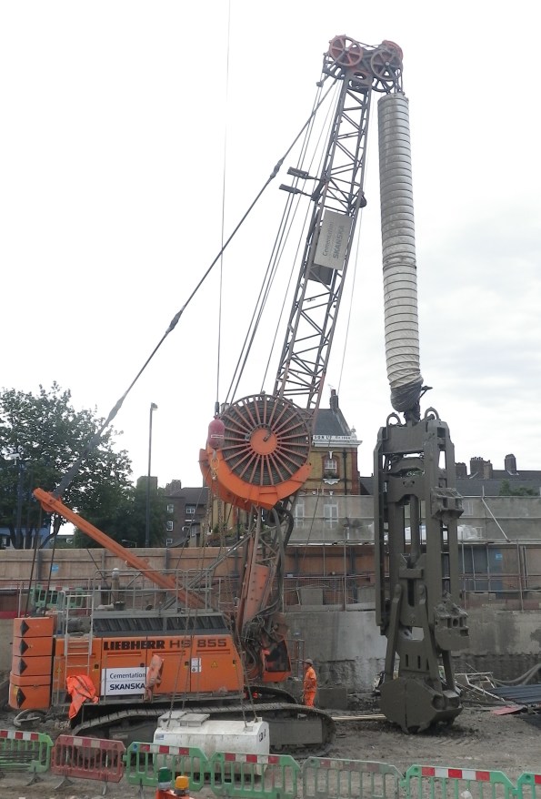
The diaphragm wall rig and grab unstuck
Options
As we stood around the rig in the quiet site we discussed three options.
1/ Use a 100t crawler crane and get it as close as possible. Then wrap a lifting chain around the cable and use both to lift together. This should add about 15t in addition to the rig.
Risks: very high risk activity using a crane to do something it isn’t designed for. Requires lift plans, method statements. The connection of chains to cables isn’t normal practice (shackles were not an option). Any slip in the cable could cause a potential collapse onto Battersea Park Road.
Impact to project: Least impact on rig if recoverable.
2/ Pay out as much cable as possible and cut all the cables and hydraulic lines from the grab. Then fix the cables through an anchor block to two100t cranes. Use both cranes to lift in tandem to get the grab unstuck, and in turns bring the grab to the surface.
Risks: very similar high risk activity using a crane to do something it isn’t designed for. Requires lift plans, method statements. Additionally
Impact to project: It would take a week or two to re-condition the grab and reconnect with new cables and lines. Lost time to project.
3/ If all else fails, cut the cables and hydraulic lines and bury the grab.
Risks: Safest in terms of H+S.
Impact to project: Despite the significant cost (£350,000) more critically it would take a long time (months) to find another grab. This would have massive effects on the project.
As we left it on Friday evening, the plan was to spend Saturday completing the necessary paper work and risk assessments to prep for option 1 and if not attempt option 2. The site was open on Sunday which suited as it would be quiet. In the end on Saturday morning the sub-contractor re-programmed or ‘re-baselined’ the software on the rig essentially telling it that it had a shorter jib allowing it to pull harder. It worked…
Why?
Now that the storm has passed there doesn’t seem to be any effort into working out why this happened. I calculated that at the depth that the grab was at, that the bottom 5m was in Thanet Sands. These are fine granular sands that are very hard (SPT tests gave an N value above 50, during some borehole testing we did across the site). I assumed that if stuck in the sands that the ground would tighten with time. or that continued pulls would only make the situation worse.
Has anyone seen anything like this before? We were lucky in this case as all the options presented significant risks. I never got to review the method statement or see the lift plan but if something had gone wrong I don’t know if the measures would have justified the risks.
Apparently Skanska got a grab stuck whilst in the Netherlands. Apparently the Belgian PC was preparing to send divers into the bentonite!!!
On a different note. The first bit of TBM has started arriving onsite.
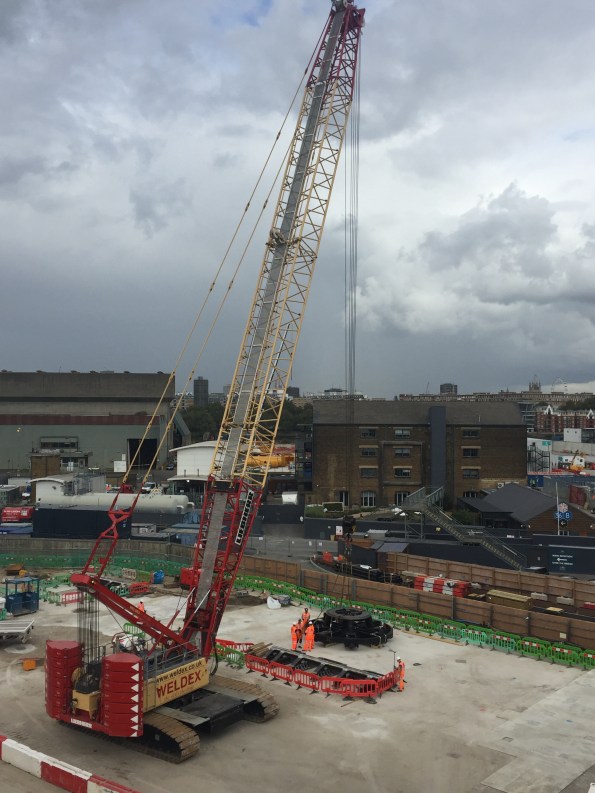
Cutter head number 1 and the 250t crawler crane to unload the TBM bits as they arrive
Pile 61 Cage Failure
A recent issue with our piling sub contractor (Skanska) has been taking up the majority of my time this week. On Friday last week whilst lifting in the top part (3 of 3) of a pile cage (Pile 61) a weld on the lifting band failed, causing three other welds to fail and the lifting band to deform. The Skanska project manager informed us that he had to stop the pile from being concreted. The lifting band is on part of the sacrificial cage that will later be removed but it there to lift and hold the cage at the right height. All good there. A good decision made on a safety and quality issue.
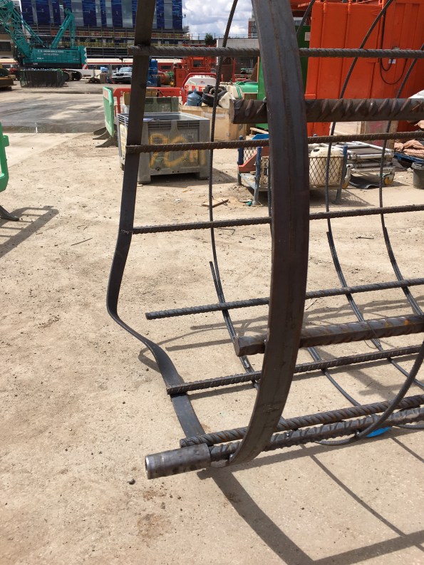
Pile 61 Sacrificial Cage Deformation
Pile 61: Diameter – 2.1m, Depth- 61m, with a plunge column.
Well, that is what we were initially told on Friday. As the investigatory wheels started turning it soon developed that not only had the lifting band deformed but that in ‘trying to make best of a bad situation’ they had taken the decision to cut off the top 2m of the sacrificial cage and tried to lift the cage from the bracing band 2m lower. This however also failed and deformed.
The decision to cut the top section and try again was not in the method statement and therefore not planned works (not authorised). The lifting and bracing bands are the same but the lifting bands have two welds where as the bracing bands only have one.
On investigation of the failed weld it is evident that there is only one weld (one side) instead of two sides, but more importantly that there seems to be no connection to the actual longitudinal bar. Very poor quality! Apparently the welder misread the drawing.

Weld seems not to have have had contact with band and not full width.
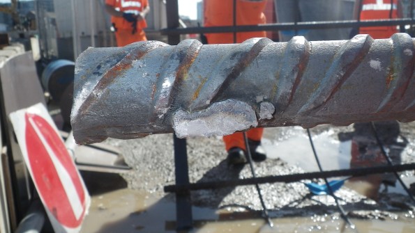
One of the failed welds, It should be 60mm (bar is 40mm diameter)
The proverbial grave got deeper as we found out that as of last week, although the cages are being produced still by the same fabricator (Express) the fabrication yard has moved from Neath (S Wales) to Newcastle. Neath went through a pretty serious quality assurance audit by both FLO and London Underground at the start of the contract. At no point was this communicated to us (the main contractor). Skanska have an engineer permanently based in Neath to quality check manufacture however do not have the same in Newcastle. Which has raised the question, how can Skanska provide quality assurance to us?
The result of all this is that we have issued an instruction to stop works until this has been resolved. This is at their (Skanska’s) cost which is evidently starting to hurt them (prelims alone are just over £10,000 a day). This morning I issued a communication (on behalf of the Project Manager) to the effect that following the site investigation diaphragm walling operations can continue however piling will be stopped until they (Skanska or Express) can provide the welding procedure, a witness statement from the welder, a CAT II check certificate for the temp wks re-bar cage remediation, revised H+S documentation and a joint inspection of the cages we have on site.
Regardless they will need to issue a Non Conformance Report as we have a 24 hour limitation for an open pile (i.e only supported with polymer fluid). But the pressure is currently on Skanska to prove the above. Funnily enough they aren’t too many smiles on their side of the office today.

The Backfill Problem
My role within the NLE project has changed somewhat over the last week. After 4 months focusing on the construction and excavation of the Crossover Box I am now the package manager for our piling subcontractor. A great opportunity to sign off some key commercial ICE attributes.
But no less than a day in the chair and I was already trying to problem solve a potentially costly issue.
The Issue
On one gridline, the diaphragm wall cut-off level is 10.4m below ground level. This wall lies between the escalator access and will form the ticket hall. It affects 135m of diaphragm wall. The question is, what do we backfill the excavation with once we have completed concreting?
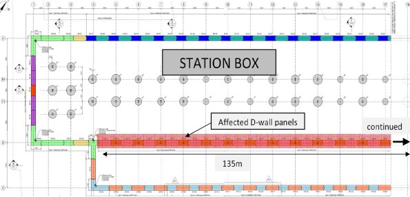
D-wall panels with lower cut-off level
The usual practice would be to backfill the excavation to ground level by concreting above the cut-off level. However not only is this a large volume of concrete (can be expensive) but it will add untold days onto the programme in breaking out C50/60 (cube strengths have been achieving 80 N/mm2 @ 28 days a.k.a. rock solid) concrete. The situation is made slightly more complex as 16 of the 45 panels contain plunge columns.
The key issue is the stability of the piling platform, this needs to be maintained whilst backfilling with a solution that will self support, won’t be too difficult to remove and can be used throughout.
What are our options?
Gravel – This wouldn’t compact enough and apparently can induce a moment on the column whilst the concrete is still green.
Self compacting gravel (pea shingle) – Wouldn’t self support and would all flow out when the stop end was removed for the excavation of the adjacent panel.
Grout – Too expensive to be a viable solution, it would require 1685m3 (135m x 10.4m x 1.2m)
Soft mix (around C10) – An option but would still require breaking out.
The proposal 1
Considering that the difference in level requires a sacrificial cage that is used to hold the reinforcement at the right level we do have a framework to work on. The initial thought was if we could concrete just the end next to the stop end. This would need to be tied as once the stop end was removed there would be very little holding back this column of concrete.
The plan so far is to install a ‘sock’ or geotextile to the sacrificial cage. Self compacting gravel will then be filled inside and outside the sock. When the stop end is removed some of the gravel will fall into the excavation but the majority will be held by the sock.
The proposal 2
The addition to this option is to concrete the end. Some sort of loop or tie is then required to stop the column of concrete from toppling over or slipping out.

Options for Backfill Support.
These are just developing options which will hopefully lead to a trial before being implemented in August. If it fails we’ll revert to the concrete soft mix option. The amount of effort being put into this leads me to think we might be trying too hard to over engineer a solution and it might be better just committing to the soft concrete option.
Has anyone has come across an issue like this before?
On a different note
The progress in the crossover box has developed quite a bit. The first two props have been installed along with the monitoring measures (strain gauges and shape arrays) which has allowed us to start excavating.


What do you do when you pour the wrong concrete?
Well, apparently nothing. A recent issue we have had at the NLE involves a situation where we “accidentally” poured the wrong concrete. Of course there were processes in place that should have prevented this but it still happened.
The pour in question was for a 2m x 2m section of capping beam 8m long. The design requires a C50/60 concrete strength (C50/60 20mm CIIIA+SR DC-3). Unfortunately the last 13m3 poured was a C32/40 20mm CIIIIA WRA Pump Mix (a Temporary Works concrete mix). Not great for the 150 year life span required by the client.
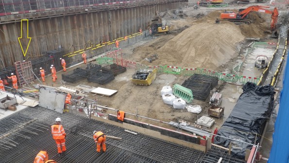
Pour 5 – South side of Capping Beam (yellow arrow)
This particular section started pouring at 1715 (a slab was also poured earlier in the day). And whilst the concrete was only just going warm and the pump was still being cleaned out the site engineer at 8pm then realised the issue. The fact that almost the entire workforce had already left the immediate call was to leave it in. The next morning, once we understood the full picture, again the decision was made to leave it in. Of course if you are going to strip it out you want to do that as soon as possible before the concrete gains any significant strength. So what was the perfect storm that led to this problem happening in the first place?
Supply
The concrete is being supplied by London Concrete, and although only one mix was ordered that day the supplier changed the mix after 8 loads (62m3) for the last 2 loads (13m3). London Concretes reason for this is that a computer crash required the staff to re-input the mix design which they got wrong. Crucially the delivery ticket did show C32/40 mix.
Checking
The site if using a sub-contractor (ESG) to conduct testing of concrete. Flow tests are taken on every load and cubes every 50m3. Incidentally they are meant to also check the mix design. The C50/60 concrete is designed to have a 600mm flow where as the C32/40 concrete is a much stiffer mix and designed to have a 170mm slump. When tested the C32/40 mix achieved 560mm flow! – so the load passed and was accepted. Quite luckily 4 cubes were taken for this load.
Pre-pour checks
Finally the site engineers are meant to check the delivery tickets, test and accept the load. Whilst they do this they fill out a pre-pour inspection sheet. Unfortunately the practice that has crept in is that the Site Engineers collect the tickets and fill out the inspection sheet later after the pour in the office. Incidentally no one noticed the difference in mix when it was loaded into the pump or when it was placed.


Resolution
Well, once the decision was made not to strip it out early you might as well leave it and see how it goes. 7 day cubes achieved 35kN/m2 so we are pretty confident that the final strength will achieve at least 40kN/m2.
Removal – If we were to remove the offending concrete (about 0.65m from the top) we would need to hydro-dem it off. High pressure water jet that strips concrete (queue much YouTube video research on what this entailed). This is apparently very cool and efficient but expensive and requires a lot of measures to protect people from flying concrete. The estimated cost came in at £200,000 to go down this avenue (not including the cost of additional concrete which would have been negligible in comparison). As the project Manager said “I would rather have to paint the beam in gold than have to strip it out”.
Re-analysis – The principle designers were good and very quick at giving their assessment within hours of being told the next morning. Their assessment is that a reduction in concrete strength reduces the bending capacity, bond strength and shear capacity. The bond strength is the most significant. However in another stroke of luck we changed the top and bottom laps to couplers to assist the construction programme which laps only in the side reinforcement. A review of the beam calculated as if it was all C32/40 and it showed that the section had adequate capacity.
The only concern Motts has is over the durability, the C32/40 design mix complies with DC-2 chemical class where as DC-1 is required. This means that we need to ensure that our backfill material is tested for sulphate content – this is an easy fix.(having had a look though Eurocode 2, I can’t see any reference to DC chemical classes. I will ask next time I see Motts but does anyone know where this reference comes from?)
Outcome
London underground have now officially received this information during a joint client/contractor/designer meeting yesterday and they are reviewing. Hopefully they should accept it but they are within their rights to ask for it to be replaced. This is a target price contract (50:50) but being a defect the cost would fall all on FLO.
In chatting with the structural engineering team they say that the reduction on concrete grade has little effect on the section capacity. I am not sure on the loads but I certainly remember quite a high sensitivity of concrete strength on the capacity of a section. Which implies that there is plenty of “fat” in the design. Additionally the impact I have noticed with the operatives is the impression that mistakes like this are ok to make which really is the wrong message. We have amended the processes on site. It was a close call which we just got away with. Had circumstances been slightly differently, we might be coating the beam in gold!
Battersea Power Station and NLE Update
Battersea Power Station
In the last few days I managed to get on a visit to the actual Battersea Power Station (part of phase 2 within the wider Battersea project) after I hosted some of the Phase 2 engineers around the NLE site. I took some pictures and thought they might be interesting.
The Power Station itself will become home to a whole myriad of things, from multi million pound apartments, roof top gardens, a hotel, cinema, restaurants, office space and event space.
I floated the idea of a fly through drone video sequence of our site to the Project Manager but he didn’t seem to interested.


NLE Update
Project milestone achieved, on the completion of diaphragm wall piling within the Crossover Box. Other than the release of funds to have a beer or two on the project it means that we can hand over some space and start the excavation. We dont the whole box as rotary bored piles still have 4 weeks left to finish so we are chasing them out of the box as we continue to excavate.
Having excavated from 101m ATD to 97m ATD the diaphragm wall need breaking out to expose the starter bars. Maximum effort to break concrete as quickly as possible without bending any bars. We are quite content with the lack of bent bars so far.


The sheet piles have started springing a few leaks. They did not have any bitumen in the clutches before they were driven. We now have a problem to either construct a small sump into the blinding layer at 97m ATD or try and seal them (very difficult to do). So far we think welding might be an option but will then require digging back out to break the weld before the piles are pulled out. Not a massive issue, but interested if anyone knows how to plug a dam? water level is at 100m ATD so no more than 3m of head.
Thermal Integrity Profiling
In a recent email conversation with John Moran, he asked me how we at the NLE were quality assuring the large diameter bored piles (2.4m diameter). Good question I said, see my next blog. Actually it applies to both the diaphragm walls as well as the rotary bored piles.
The walls of the Battersea Station boxes are constructed with diaphragm walls. For those who don’t know (because I didn’t really until I got here) how they are constructed here’s a brief explanation.
Diaphragm Wall Construction
The piling rig looks similar to a rotary rig except that it has a massive set of jaws, instead of a rotary auger. I believe a diaphragm wall works like a secant pile wall though I am open to being told that I am wrong on this one.


The rig can cut a panel 1.2m deep, 2.6m wide (or wider) and almost as deep as you want. Each panel is dug under a bentonite slurry to support the excavation during the dig. A deep dig can take up to 7 days to excavate. Once excavated a reinforcement cage is dropped in and it is then concreted using a tremmie pipe.


In TIP, a fibre optic cable is tied to the side of the cage. The technology uses a laser to shine a light through the fibre. Temperature is recorded by measuring the scatter backlight down the fibre at 1cm intervals. The system is accurate to 0.5°C.
The Bottom Cage showing the Fibre Optic Cable already laid out and two reels ready to extend to next cage.
The instrumentation starts logging as soon as it goes in the ground and records for 48 hours after that. The output looks like the temperature diagram below.
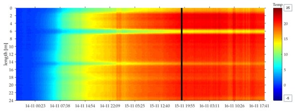
Thermal Profile Over Time
The cold spots around 6 and 14m depth correspond to the boxed out sections where we have rows of couplers that will eventually connect to our floor slabs. The box out in effect shields the concrete from the surrounding soil changing the thermal profile. This also allow us to confirm that the couplers are at the right height.
For comparison, the first three panels were tested with sonic testing and TIP as a comparison. Since it was accepted as a valid method of assurance only TIP testing has been carried out on each panel. As the graphs below on the right show, sonic testing can only verify between the tubes and not outside.
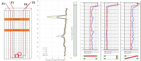
TIP vs Sonic Testing (L-R Lay out of fibre optic cables, TIP testing, Sonic Testing)
In short, this seems like it will be the future of assuring the construction in deep large piles. The advantages of easier installation, testing coverage area and time of recording make it worth the initial cost of the system.
I know that Expanded (Laing O’Rourke piling specialist) use thermo-couplers but I believe that they only record every 30cm and can be quite temperamental.
CFS-N205-2360000-CIV-RPT-00028_Iss1
NLE – Battersea Station
Last time I spoke about the project in general so here is a bit on the detail of the project, specifically the Battersea site of the NLE (Northern Line Extension).
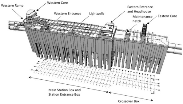
Station and Crossover Boxes
The whole Battersea site simply splits into two boxes. The Station Box is the bigger of the two and is where the majority of the station is going to be situated. The crossover Box is smaller (about a third in length) but still as deep. This box is simply allows the trains to cross from one side of line to the other before it pulls into the station. The Crossover Box is also the launch and access box from where the TBMs will be dropped down and also act as the area to dig out the launch tunnels.
The design for this is essentially Ex Cofferdam on a much bigger scale, just replace sheet pile walls with Diaphragm Walls. Although the D-walls themselves are being constructed inside a 5m sheet pile wall secondary cofferdam. The D-walls vary in panel width (2.6m to 4m) by 1.2m and are saw toothed (see picture), essentially because the shorter ones are as deep as the bottom slab and the longer panels which are 60m long are mostly end bearing onto the layer of Thanet Sands. More on the Thanet Sands another time.
Tunnels
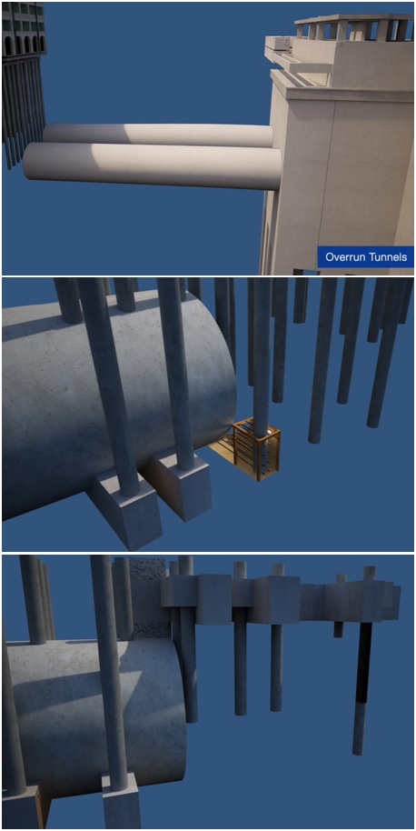
The tunnels are relatively self explanatory except for the bits that won’t be done by TBM. The first 200m on the East side (TBM launch tunnels) and about 200m of over-run tunnel on the West side will be dug manually (well mechanically but not by TBM) and then spray lined with concrete. The over-run tunnels are quite interesting as these are apparently part of TfLs plan to secure a future extension to Clapham Junction (no present funding available). These overrun tunnels will go through the pile foundations that the Battersea Cats and Dogs home.
There is cunning plan to dig up to the piles and prop around them/ tie them together in a move that the NLE Construction Manager admitted to me “will most likely break all the windows in the building”. Though they did get a massive extension that triples their space to keep them happy. The following pictures are a bit of that sequence from a video that shows the process.
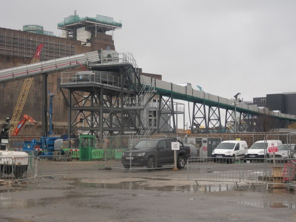
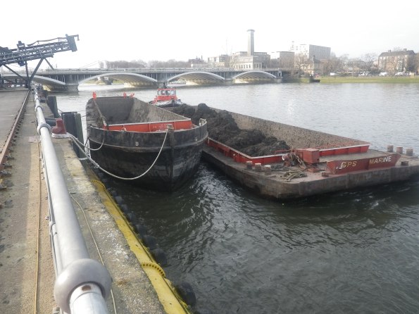
Muck Conveyor
Finally worth mentioning the much conveyor which has been installed to allow muck to be carried away by barge. From a cost point of view it the £16 per tonne compared to around £300 per tonne by road seems an easy decision but when you factor in the £5 million initial cost and maintenance of the conveyor over the length of the project it nearly breaks even. But it does save hundreds of road moves through London which goes a long way to reduce carbon emissions and keep the locals happy. At present the conveyor is loaded from a muck bin and we are moving about 1000t a day. Eventually the conveyor will extend to the bottom of the crossover box and will connect directly to the back end of the TBM running 24/7 (about 4 barges a day).
The project to date
As we speak, Cementation Skanska (principle sub-contractor) are about 2 weeks away from finishing D-wall construction in the crossover box along with a few weeks of rotary bored piles in the centre (1.8m to 2.4m in diameter). Cementation Skanska are very much on the critical path and will be handing over parts of the box to us (FLo). So where as so far the pressure and risk is somewhat on Skanska it will soon shift to us to prep the crossover box for the TBMs. As I have quickly learnt, anything linked to the TBMs are pretty much on the critical path.
NLE Project Introduction

I started on Monday this week on the Northern Line Extension (NLE) at the Battersea Site. The project is a JV between Laing O’Rourke and Ferrovial Agroman known as (FLo).
The project client is London Underground (LU) tho
ugh the extension and stations are heavily integrated into the whole regeneration of the area. So Battersea Development (who are part funding the NLE along with 41 other developers) are leaning quite heavily on London Underground. Phase 3 of the Battersea development will sits on top of the station box. A big change to the structure caused a change to the design of the station which has resulted in an 8 month delay, and the design for the station is still being finished. Regardless, the political pressure (Boris Johnson’s office) would still like the development to be finished for 2020. I believe the commercial teams are still debating who will pay for this. The change to the structure caused the design to be changed delaying and extending the project length.
The Project
The project is a 3.5km extension of the Northern Line which will continue the Northern Line from Kennington with two new Stations at Battersea and Nine Elms. The line will have 100m overrun tunnel (under the cats and dogs home) which will serve to store two trains over night for morning service. That tunnel will eventually connect the line to Clapham Junction. The value of digging just 3.5km with two TBMs is apparently justified. Clapham extension too can’t be done now as there are no funds and apparently Clapham junction cant take the additional capacity just yet.
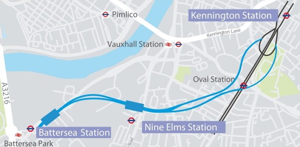
In outline, the project is split into four sites. Two stations at Battersea and Nine Elms and two shafts at Kennington. The box at Battersea will consist of the station box and a crossover box. The crossover box (space for trains to swap sides before they return) will be used as the launch tunnel for two TBMs (Tunnel Boring Machines). The station at Nine Elms is relatively independent other than they must be at depth before the TBMs arrive. The last two sites are the shaft that connect to the existing line at the Kennington Loop where the TMBs will be lifted out. The shafts will then remain as ventilation and emergency escape for the tunnels.
Joint Venture.
I understand that Ferrovial were brought onboard primarily for their tunnelling experience where as Laing are taking the lead on the station boxes and the shafts. Despite this the site office is a 50/50 mix from both companies. I understand there is a slight friction with the Spanish side of the team as they are very commercially savvy but see the role of a site/section engineer in a very different way. Commercially sensitive material is apparently spoken in Spanish which makes by ability to speak the lingo quite helpful.
