Archive
Underpinning, Tea & Railings
It has been a busy and interesting couple of months with Michael Barclay Partnership in London. I’ve committed a couple of weeks to learning AutoDesk’s structural modelling software, Robot, amongst other design work. It has been somewhat frustrating to get the hang of, since the slightest fault in the model can cause the model to terminate the analysis. This means you need to de-construct the model to find the fault. This can be exceptionally wasteful of time. The software also crashes inexplicably so you can lose a lot of work if you don’t save regularly!
Modelling Cabul Road
The key principles when modelling with Robot are therefore to:
- simplify your structure as far as possible
- only model what you need
- verify and mesh the structure as you go
- know what results you need and what they should look like
- save regularly
Progress on the Cabul Road redevelopment project is ongoing, but somewhat slow. Planning permission is still outstanding and it is likely now that changes to the massing of some units will be required. I have completed a prelim structural scheme, outline demolition drawings, temporary works design to retain a terraced gable wall that will be exposed with the demolition of 4 properties. I’ve also designed the two new large roof structures in structural steel. The project also requires significant underpinning to the existing structure and party walls. I have had to research and learn about the Party Wall Act and what the responsibilities of the developer are. I also understand about Demolition Notices and the Planning Procedure. Other interesting points on this project has been to determine the disproportionate collapse class (the fifth floor of the flats is less than 50% of the total area), basement waterproofing strategy, positioning of movement joints and structural floor choice.
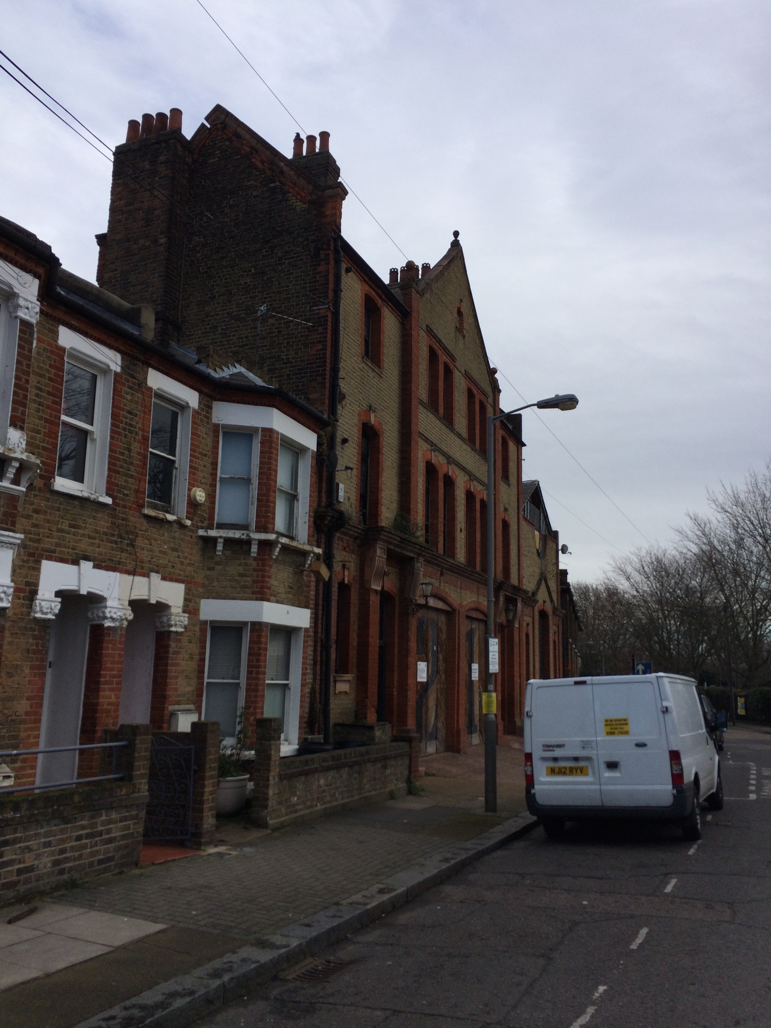
21 Cabul Road
I have also been involved in some other projects. One of these is Albion House, in Woking. It is a disastrously ugly and unsightly 9 floor tower next to the train station. The client’s aspiration is to redevelop the tower and maximise net lettable space, either by removing one of two stairwells, or placing another storey on the roof. The advice that I have been able to provide with MBP is shaping how the clients are costing the alternative business cases. More work is to follow on this one.
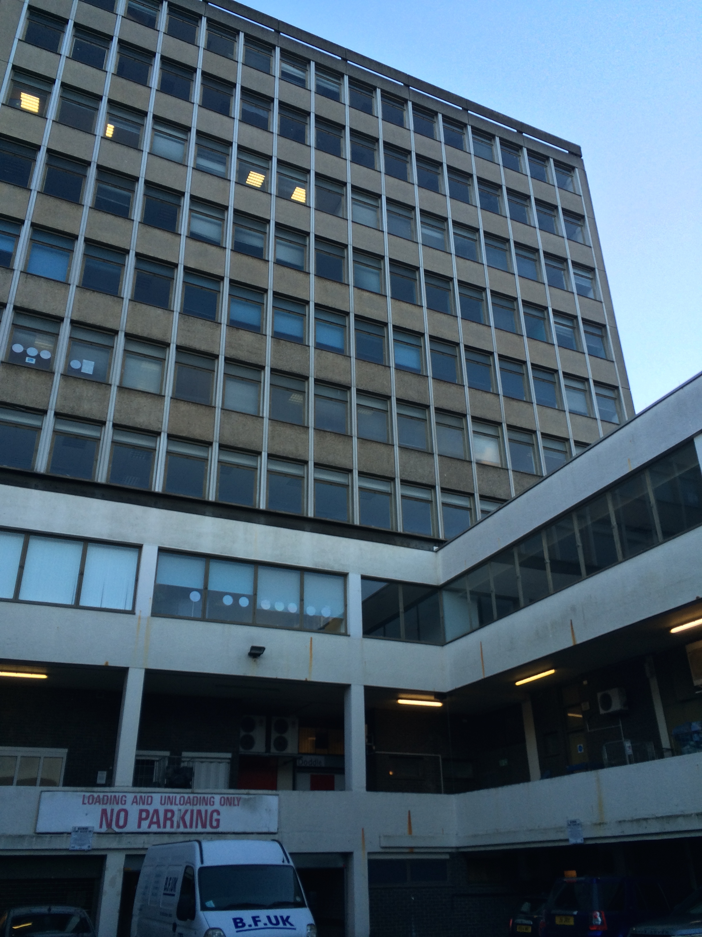
Albion House, Woking
Michael Barclay Partnership support UCL and I’ve become involved in a mentoring scheme. As part of this I am mentoring a 4th year Masters student who is undertaking their design project. It has so far been an interesting and enlightening experience into mentoring.
In other news, I managed to pour a whole mug of hot tea into my lap whilst in a client meeting last Monday. I then had to spend the next 15 minutes drying my trousers under a hand dryer in the loos! And to cap it off when I ran home on Thursday I tripped and impaled my right hand on some spiked railings! I then spent three hours in A&E and the whole of Friday getting surgery. I’m now sat at home with my hand stitched and bandaged like a boxer!
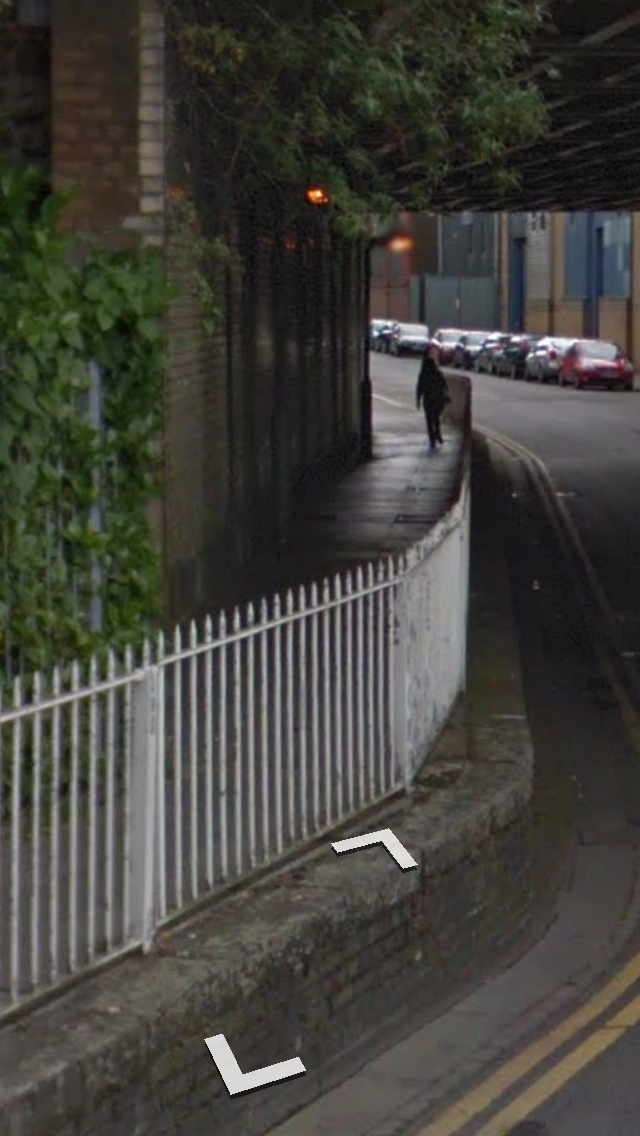
Here are the railings.
The question is, why are there spikes on a guardrail at hand level? It is all rather inexplicable to me! To frustrate me more, having paid PAX personal injury insurance for years since my wound wasn’t from a knife, blast or bullet I don’t get bugger all from them!!! Thanks.

I hope your week was better than mine!
The Queen is not the best landlord
I’m working with a small firm of consulting structural and geotechnical engineers called Michael Barclay Partnership (MBP) Limited Liability Partnership (LLP). They employ roughly thirty engineers, ten CAD operators and some admin staff. We’re based on the Strand, just down from the Savoy Hotel and the building is owned by the Queens personal estate. Sounds great right? Well our office is on the top floor of the building and we’ve had no heating since Christmas!

The firm’s business model is to achieve a high turnover of work on small to medium sized projects in London and the South East of England. Their work is predominantly in domestic/residential structural design of new build (or redevelopment) projects, but they also have public, retail and commercial projects on their books.
The role I have taken up is as a Junior Structural Engineer. I’ve been given responsibility for the design of a residential development in Battersea, which I have been working on full time. The developers budget for the project is approximately £5m. The design fee will be no more than 1.5% of this. In addition to this design work, I have been on a number of site visits around London (or simply the Royal Borough of Kensington & Chelsea) to gain practical experience of basement construction, underpinning and significant structural alteration works.
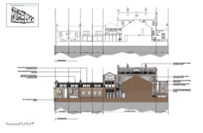
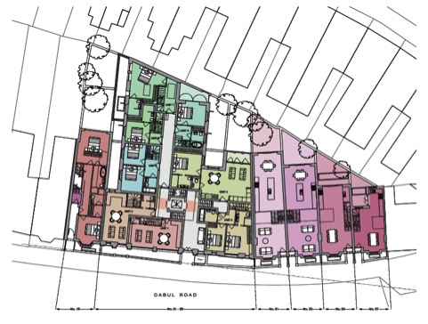
The project in Battersea I am responsible for is the redevelopment of a Baptist Congregational Hall built in 1895. The developer hopes to convert the Hall into thirteen flats. Adjacent to the Hall are five terraced properties. It is hoped to demolish four of these and replace each of them with new 2×2 bed houses (these are the four properties to the east on the below plan).
I completed a Desk Study and Construction Method Statement for the planning application, which was submitted just prior to Christmas. Since then I have worked on the Concept Design of the development. Once my line manager, one of the four principals of the LLP, approved this I moved onto the Developed Design. I am now in the throws of modelling the structure such that I can verify my concept design. After this I will finalise the Detailed/Technical Design.

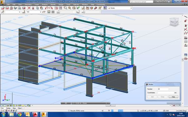
The last five weeks of design office time have gone exceptionally quickly. I feel as though my learner plates are coming off at last. A little like Joe’s office, most people design using British Standards. I’ve opted for EuroCodes and this doesn’t seem to be a problem. The last week, or so, I’ve immersed myself in learning how to model structures using Robot, which is part of the AutoDesk family. Here his a screen grab from one of my models.

It is a pretty powerful tool and I’m now just about getting to grips with it. We also use Tedds which is great for very speedy verification of simple elements, and 2D analysis. Some of the structural challenges ahead of me include retaining the front and side facades of the Congregation Hall, underpinning the retained facades and party walls to dig the basement, erecting new roofs, designing a new core within the building and installing a new steel frame within.
Monitoring the planning application online for the Battersea development a lot of local residents have objected to the fact there is no off-street parking. The developer did commission a parking study but this was done on a Wednesday afternoon in mid December and showed there were plenty of free parking places! The residents are up in arms with this since it is not representative of their parking ‘crisis’. Therefore I won’t hold my breath that planning with get the green light immediately.
All in all it should be a good five months ahead. There is plenty of interesting work coming into the office which I will no doubt be involved with.
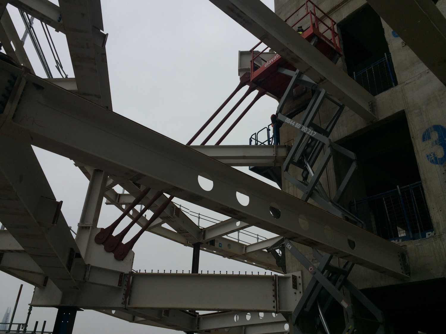
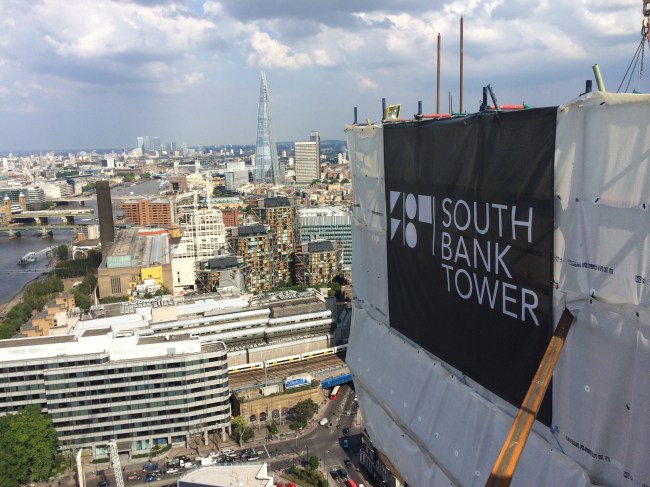
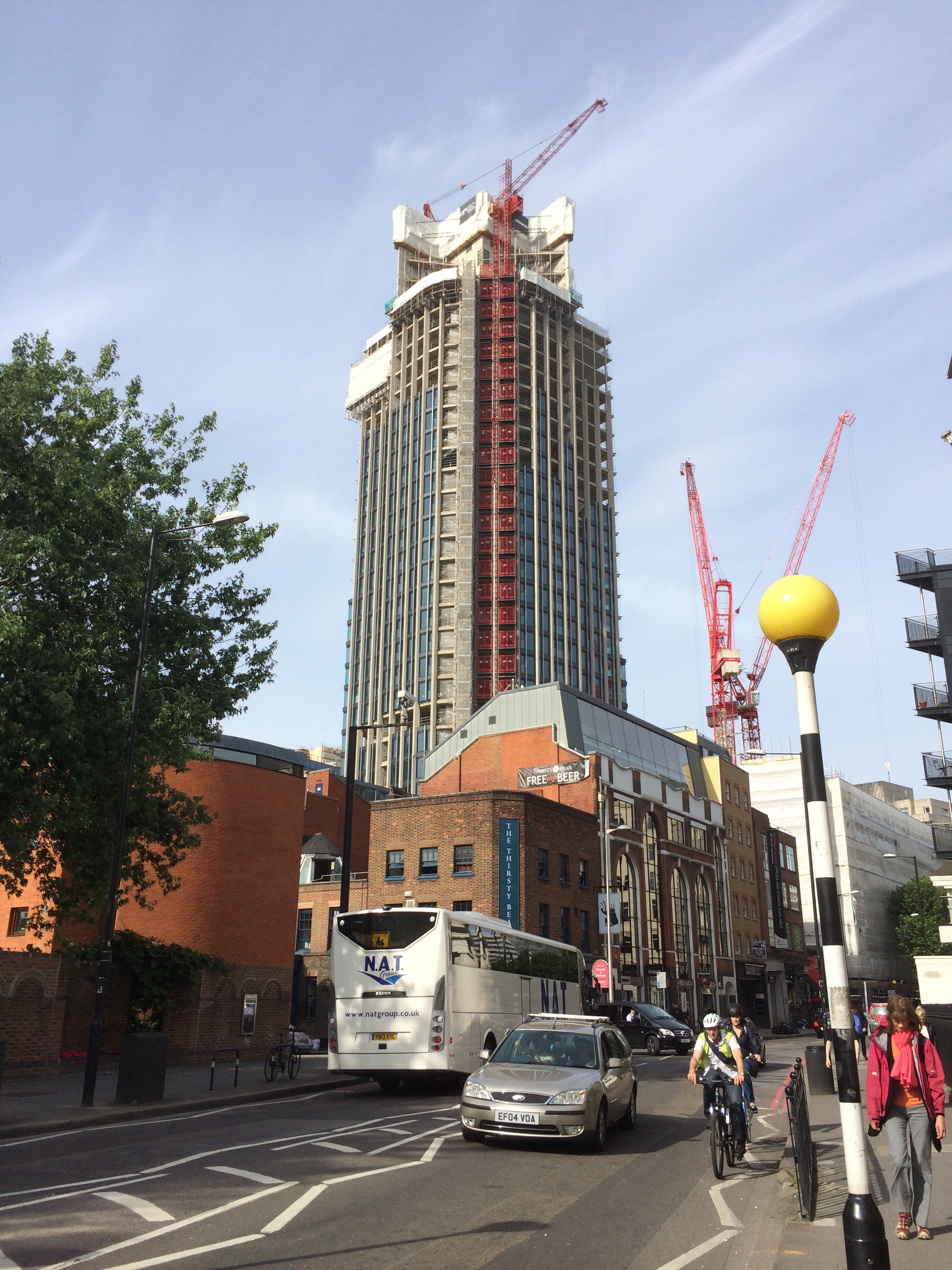
Installation of the six mega embedments at the South Bank
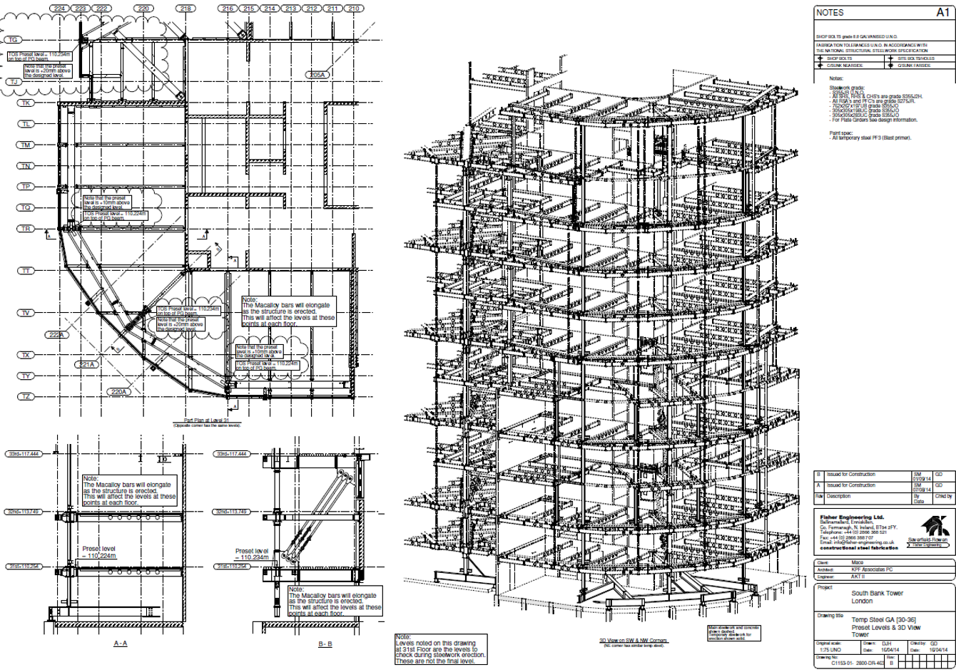
 In an early blog I described how the load path of the new steelwork on the tower extension is pulled up and into the core through Macalloy bars.

This is required since the existing pre cast columns crank inwards towards the bottom of the building, inducing a large moment that cannot be dealt with.
The existing column crank can be mid picture
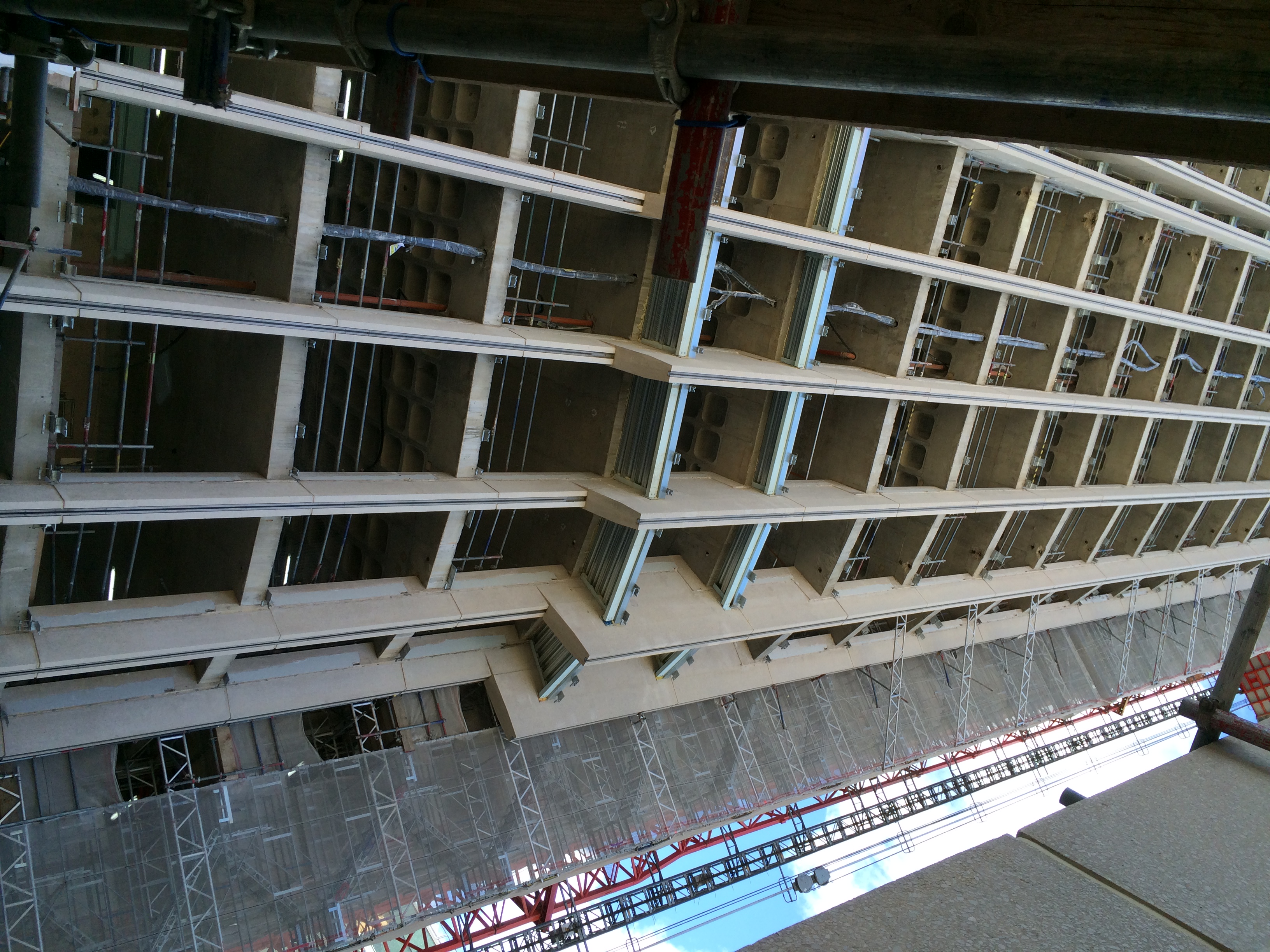
In the temporary construction condition, whilst the diagonal Macalloys are not employed (because we were building them) the weight of the steelwork is propped off level 30.
This load passes down the existing pre-cast perimeter columns and into the foundation.
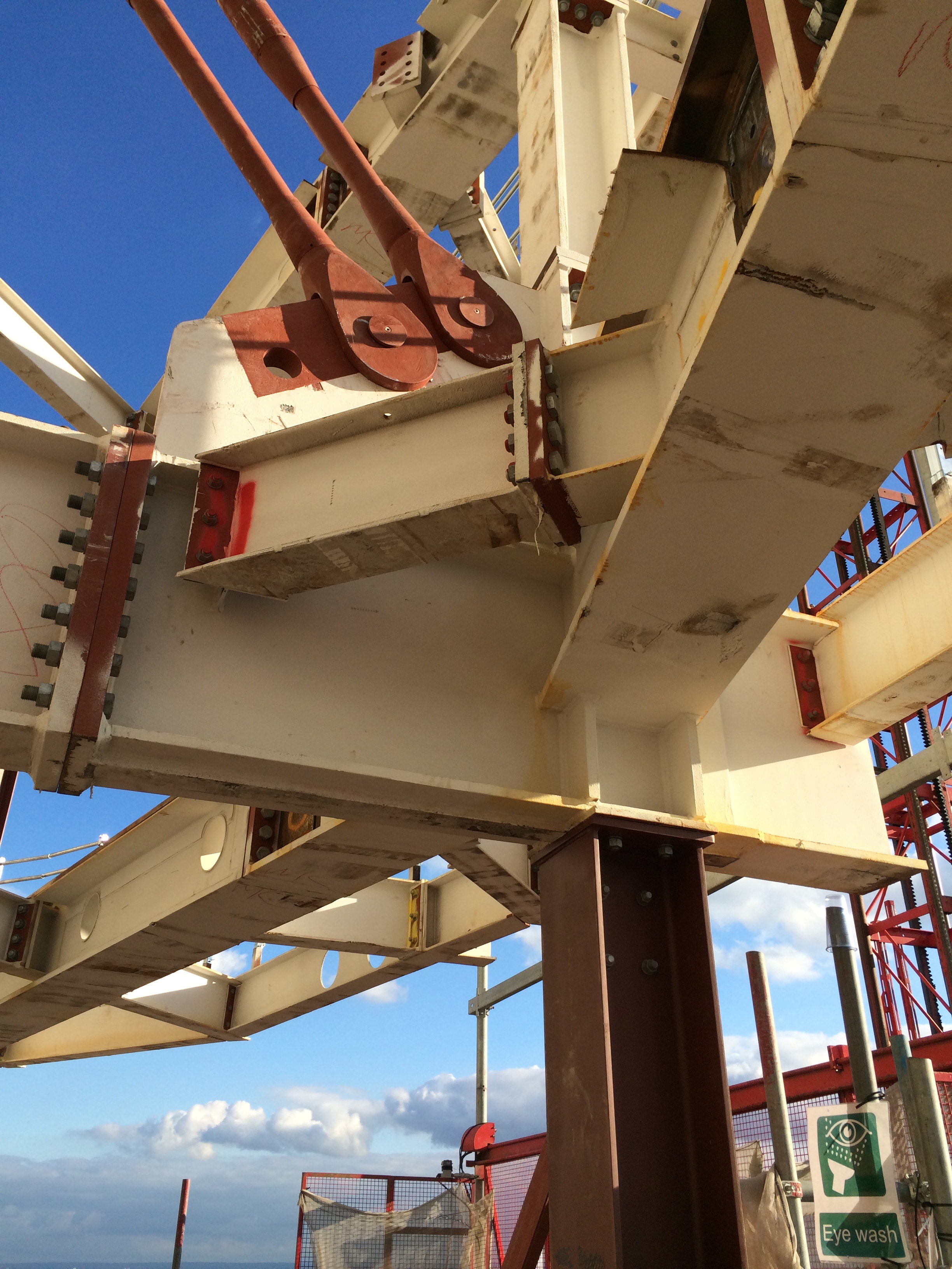
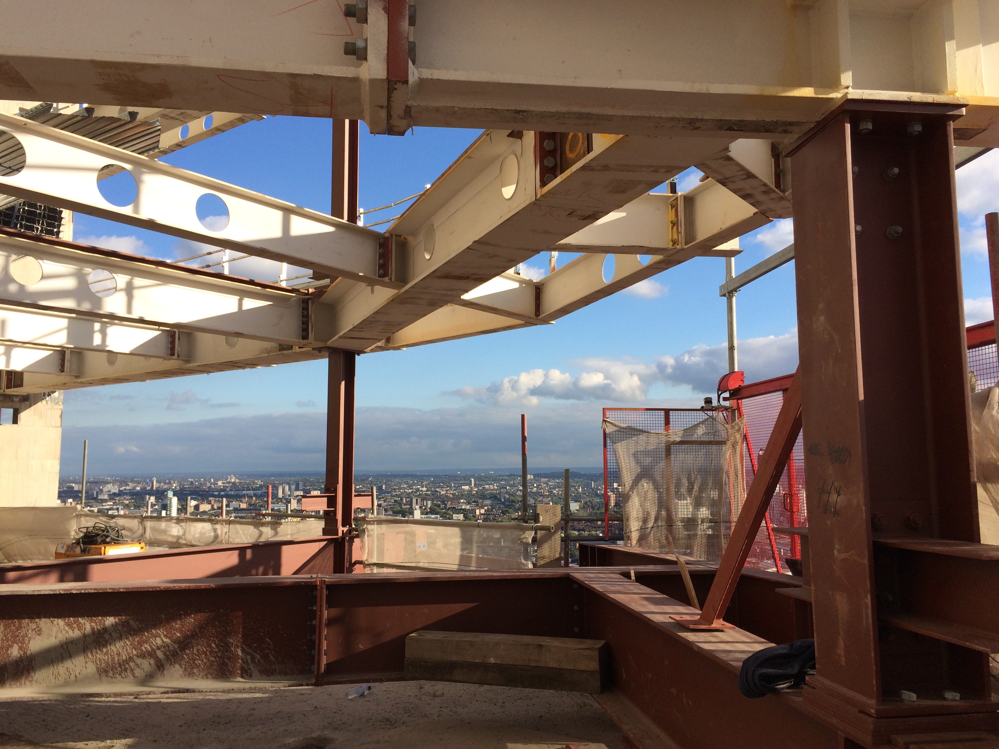
The red steel is the temporary steelwork sat on the top of the existing columns
I undertook analysis of the existing structure to determine how much steel we could erect before we reached the limit of the crank. I can report that my calculations to determine the allowable load were alright since the building is still here. Knowing the actual factor of safety during this operation was exceptionally difficult so we will never know how close we were.
Installation of the hangers has been slow because of a number of issues.
1. PC Harringtons did not cast the correct size holes/voids in the core to allow the mega steel embedment to fit into. This required us to break out additional concrete.
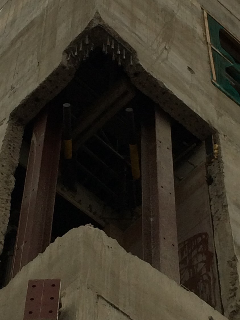
Void for the embed
2. The slipform at the top of the structure meant we could not lift the embedments into the holes until the slipform was completely removed/dismantled. This meant there was no concurrent activity

Back plate in place
3. Access to the embedments is difficult. We used a combination of traditional scaffolding, proprietary platforms and scissor lifts to access the embedments.
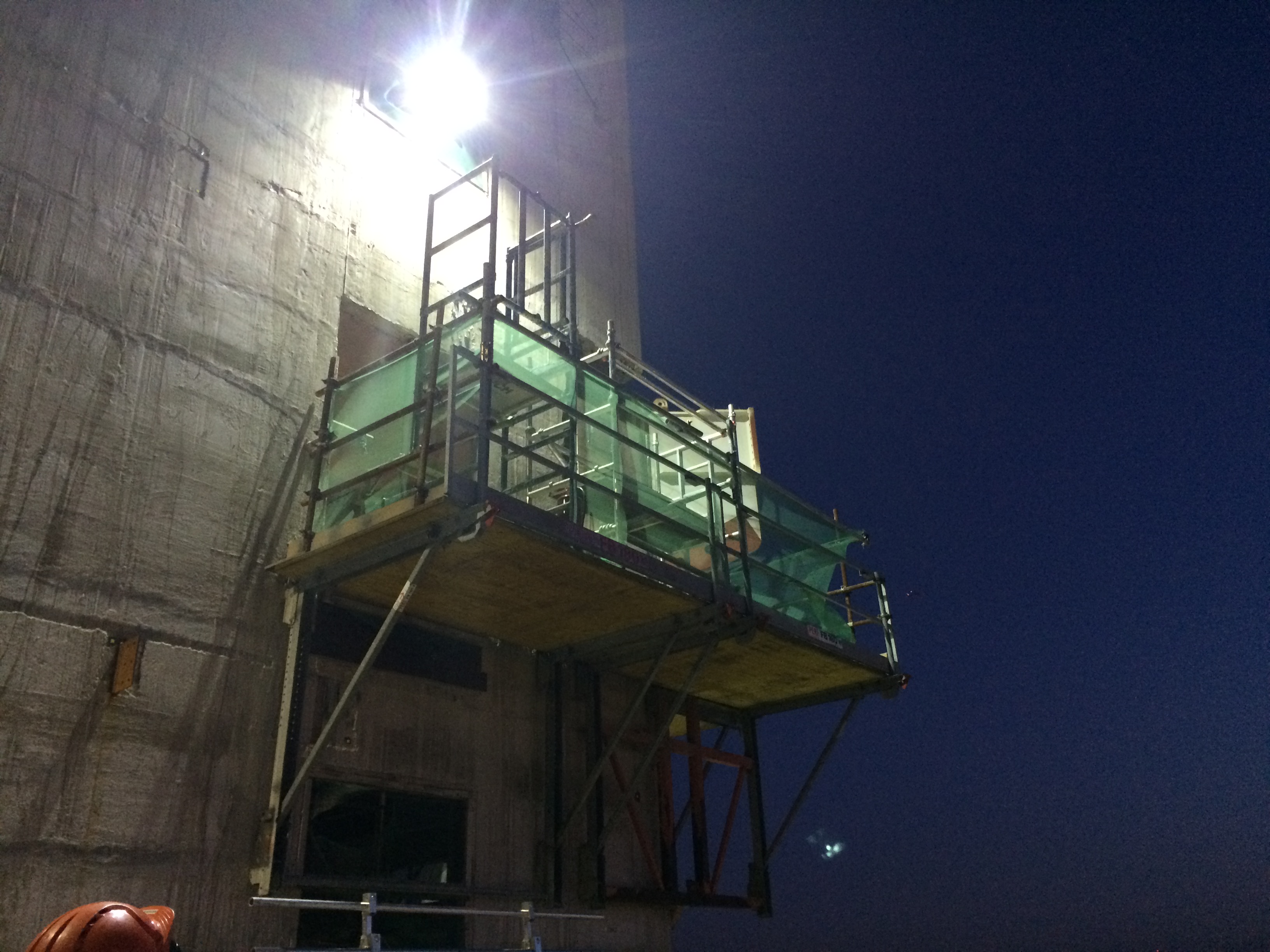
Access to the embed
4. Since the embedment elements are critical to the structural integrity of the permanent works each segment of work has to be inspected and signed off by the structural engineer, Mace and sub-contractors prior to moving on. This took a lot of my time as well as wasting progress.
5. Our resident engineer on site is useless. Although he is supposed to be a qualified engineer, he is not willing to take any responsibility or give a direct answer to anything. At every instance he has to refer back to his office for advice.
6. We are dealing with two sub-contractors to deliver the one element. This has required almost daily meetings to ensure progress is maintained.
So what.
- I think we could have planned better for this operation (who never says this?)
- Design information was scant. Its lack of detail seems to have then impacted upon the whole operation. Since there were so many unknowns I think higher risk was accepted prior to construction than really should have.
- We should have used 3D software to map out how the reinforcement and steel interfaced. The slipform precluded particular vertical reinforcement being fixed during slipforming. This should have been picked up. We were then in a position fighting to get hold of every piece of reinforcement that was available.
- The Structural Engineer’s designer of the embedment elements should have given us a presentation of how he designed them, and why particular elements were important. This would have allowed us to make more informed decisions on site and understand risk better.
Macalloys in place
So inclusion.
Communicating how a structure or element of it is designed is key. If the contractor doesn’t ‘get it’ then there is real risk failure could occur. Sub-contractor engagement, liaison and partnership is key to ensuring that shared progress is optimised. There was little motivation for the concrete contractor to get the job done, but lots of motivation for the steelwork contractor. Modelling of complex nodes, connections and elements is worth the time, effort and expense as it ultimately reducing time, cost and improves quality on site during the installation.
Here are some other photos of the embed.
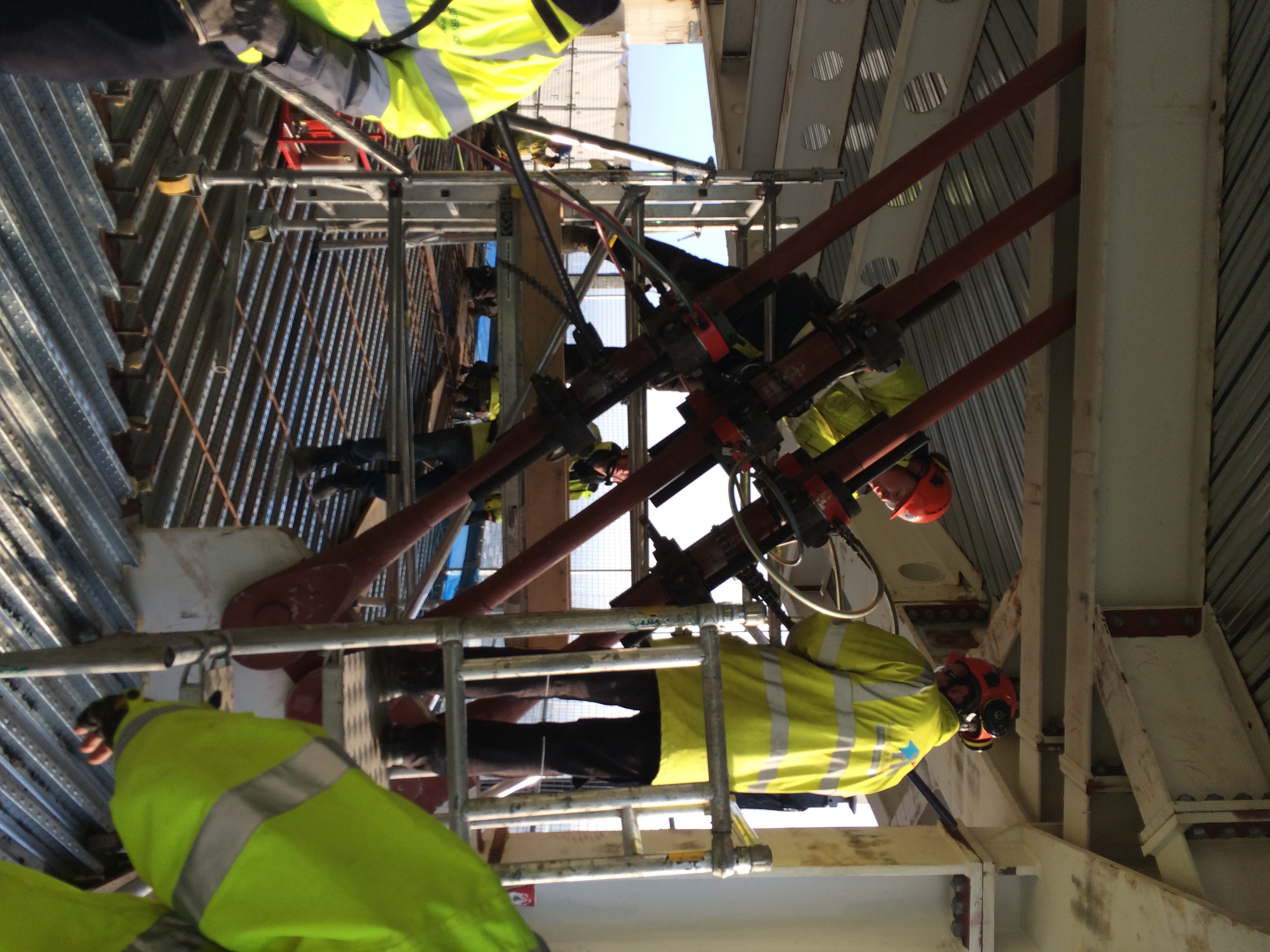
Jacking in progress

Lift off once the macalloys were tweeked
Something for Joe since I sent him to sleep with my last blog!!! The Worlds Biggest Crane
The article below was taken from the Mace news page, and again I thought it was quite interesting!! I’m hoping I don’t miss the mark again Joe! Nothing like a bit of crane ‘appreciation’ top trumps!!!
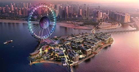
How to build the world’s largest crane
Faced with building the biggest observation wheel in the world, the Dubai-I team is no stranger to challenges or to beating records. And this month was no exception with the delivery and erection of the Mammoet Platform, Twin ring Containerised (PTC) 200DS, the world’s biggest crane.
The PTC 200DS was designed and built by Mammoet in Holland and has spent the last two years in Texas working at an offshore oil assembly depot lifting a 120m spar as part of a deep sea drilling platform. It was disassembled in April 2014 returned to Holland, cleaned, maintained and thoroughly inspected prior to travelling the 6000 plus nautical miles to the UAE Port of Jebel Ali.
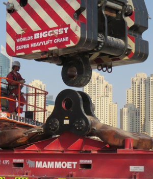
To transport the huge crane the 221 containers had to be offloaded and then placed onto articulated vehicles where they were then transported by road to the Bluewaters Island site in Dubai. They were then offloaded by one of the three crawler cranes and laid out in order of erection sequence by the site based team of trained Mammoet erection specialists. The crane is so large that the operation required one LR1600 crawler crane @ 600Te capacity, two No 250 tonne and one 180 tonne crawler crane sited in the unloading and distribution area.
During the erection there have been several critical lifts, in some instances three of the four crawler cranes were used to carry out a single lift. The critical lifts have been impressive and professionally executed by the Mammoet erection team. The most demanding of these was the lifting of the back mast from horizontal to 70 metres with all cranes travelling 60 metres in unison whilst lifting a load of 340Te.
Senior Project Manager Piers Sidey said: “The fact that this will be the largest observation wheel in the world by some margin presents huge challenges on several fronts. The designers are pushing the boundaries to find effective and economic solutions. When you double in height the forces, stresses and deflections are magnified many more times. Secondly since we need to maximise off-site assembly as far as possible the wheel will be delivered in very large pre-assembled sections up to 118 metres long and 1800 tonnes in weight. Hence the need for one of the biggest cranes in the world.”
The Mammoet PTC in numbers:
221 containers required to transport PTC200DS
3,400 tonne lifting capacity
830 tonne – weight of Dubai-I leg
1,800 tonne – weight of Dubai-I spindle and hub which will be single lift at over 100m high
123 metres – length of boom
55 metres – length of jib
182 metres – total height at tip of jib
87 Te – weight of hook block
123 metres and 415 tonne – heaviest lift during construction by three cranes
Here is a pdf with some more info of the process of DubaiI crane process.
Temporary Works and EuroCodes
I noticed an interesting article in the NCE mag this week (kind of rare I know!) about the relevance of EuroCodes to Temporary Works design and the use of the term ‘Safe Working Load’ (SWLs).
The key issue the author brings up is how do you use a prop with a ‘Safe Working Load’ in a EuroCode compliant design? Was the prop originally designed to EuroCode? Is it ok to assume the ULS capacity is 1.5 times the manufacturers stated SWL?
Having done a few temporary works designs now using just SWL (with no factors at all), as well as with ‘old BS’ verification and new EuroCode verification it certainly is a bit of a muddle. Proprietary equipment specifications can have a myriad of terms which can be confusing, so sticking with Safe Working Loads in my view is essential.
Has anyone come across this problem???
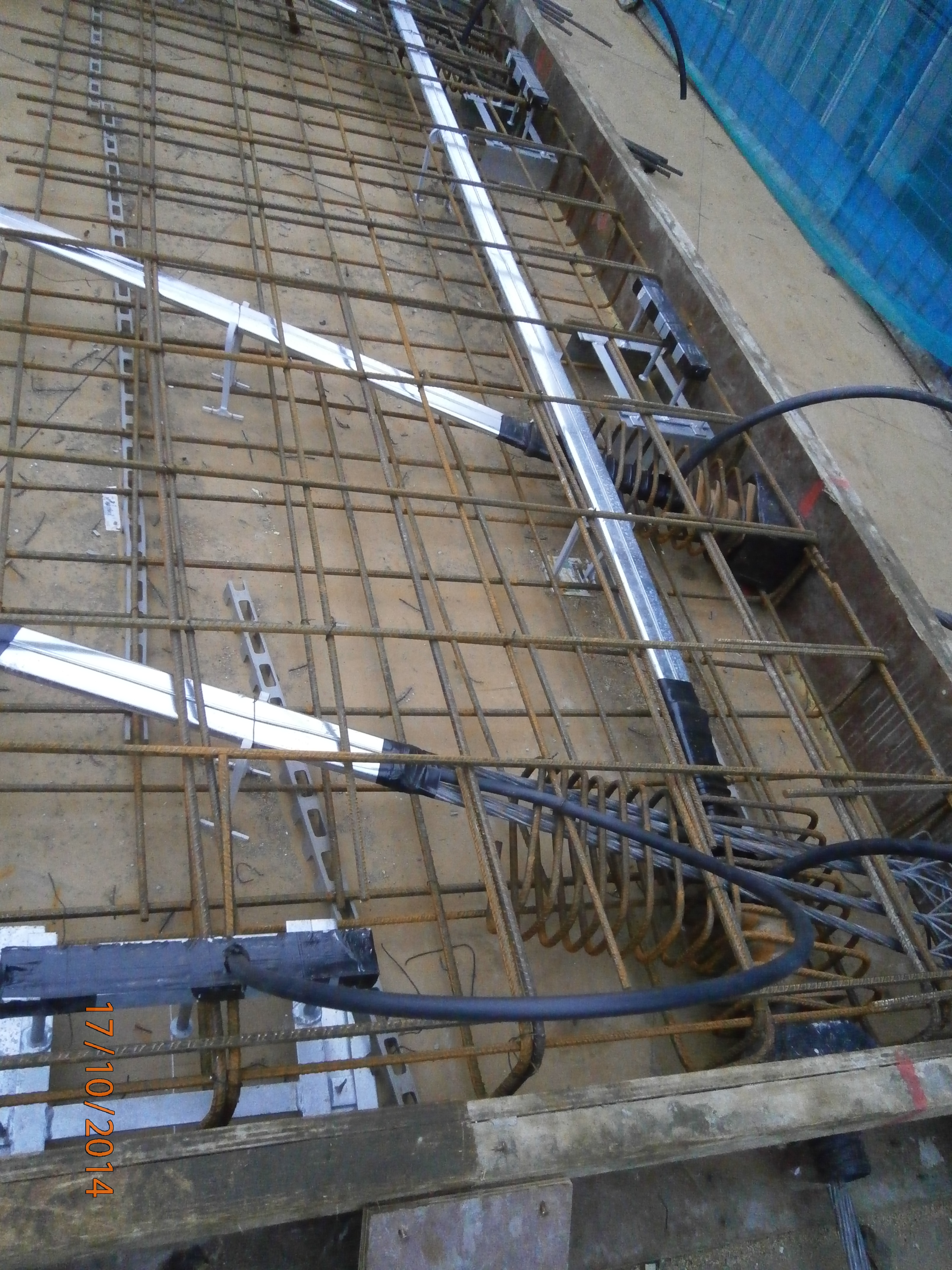
PT slab – Live end with ducts
In response to Rich Farmers comment on ‘where are the sheaths?’, here is a pic of the live end. Sheaths/ducts in place and taped up with grout tubes poking out.
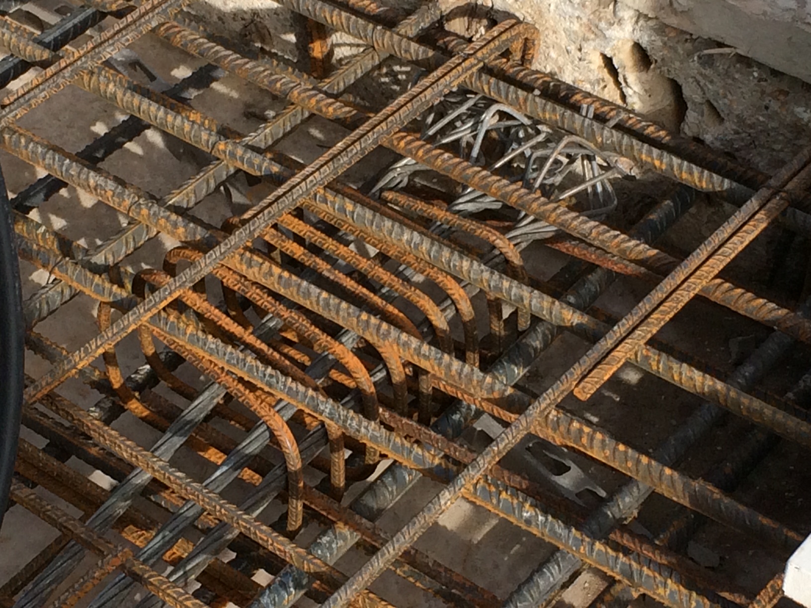
PT Slab onions
Here is a photo for the phase 1 guys. We talked on site about the PT tendons. This is what the dead end of the PT tendons looks like with the splayed onion end in order to anchor the tendon in the slab. The spring like coil of reinforcement is for bursting. Enjoy Ex Waterloo. Rich
Cranes alongside railways
As well as my work on the South Bank Tower I am also the Construction Engineer for Mace at a small site in Lambeth, at a Metropolitan Police Station. This police station is a forensics lab, headquarters for a firearms unit and also a communications HQ for police and fire calls.
Maces scope of works is predominantly M&E. We are relocating the existing plant onto the roof of the existing five storey structure. Originally built in the early 1970s it was first used by the Royal Mail as a sorting office and as such is a very robust structure with 14 and 18inch thick floor slabs, with RC columns in approx. a 10m grid.
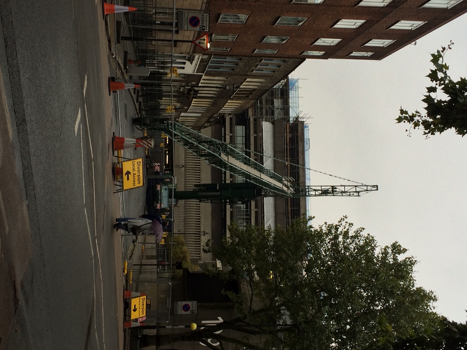
In order to relocate the plant onto the roof, a steelwork grillage is to be built in order to allow the high permanent dead loads to be bear directly on top of the existing RC columns, instead of the roof which obviously is not strong enough. Being London the site is particularly constricted. To the east is the rail mainline into Waterloo (the Reading line), to the south a narrow road, to the west there is no access since there is a hotel and to the north there is a small residential street used by the police for access.
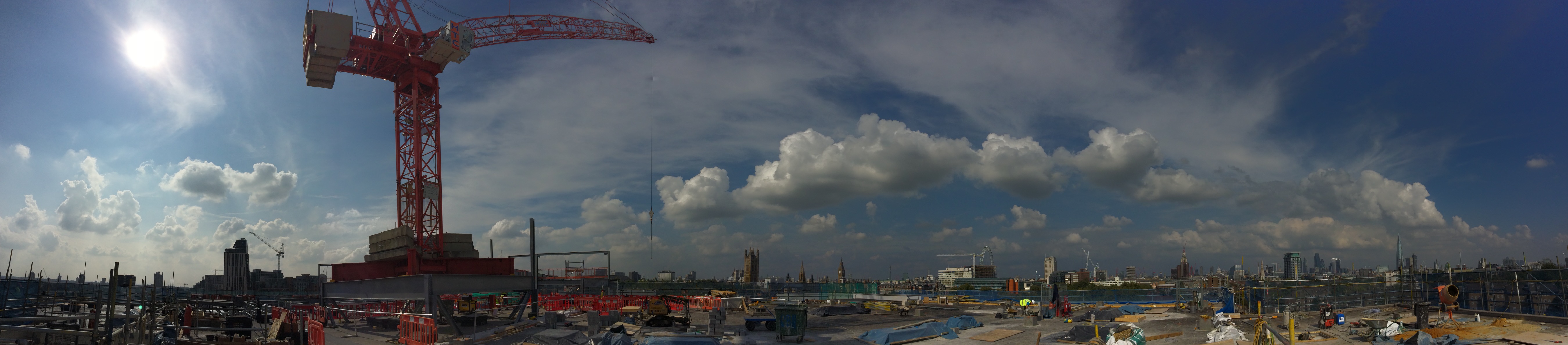
The key challenge for me has been to plan how to erect a tower crane on the roof of the existing building, which will lift all the plant into its position. This needed to be achieved with limited access and immediately beside a live railway. Network Rail require anyone working beside the railway to have an agreement in place and any works which could impact the railway to be signed off by their Railway Asset Protection Team. As part of the approval process the principal contractor has to nominate a Designated Project Engineer (my role) and a Contractor Responsible Engineer (min Chartered Engineer).
Network Rail operates in a risk focused manner. They trust nobody and everything that could potentially impact the railway is scrutinised to ensure the risk has been appropriately managed. Obviously using a mobile crane to erect a tower crane on the roof of an existing building and then operating a tower crane to lift pieces of plant, up to 10 tonnes in weight, is relatively risky.
Managing the risk effectively, thereby reducing the level to an acceptable level for Network Rail, required prolonged engagement and forward planning. We had to demonstrate we had explored all alternative options and the chosen option then had to be designed and category III checked. This task was doubled with having to design and check both the mobile crane, and the tower crane.
Tower Crane Grillage
For the tower crane, in order to progress the early design of the tower crane I undertook initial design feasibility to determine the scheme was viable and also give the steel fabricator indicative sizes of beam for pricing. I then gave the detailed design and analysis of the crane grillage (utilising the permanent works steelwork) to a temporary works designer to complete. In order to verify the existing structure was adequate to support the tower crane loads, combined with plant loads, I then undertook a detailed analysis of the building.
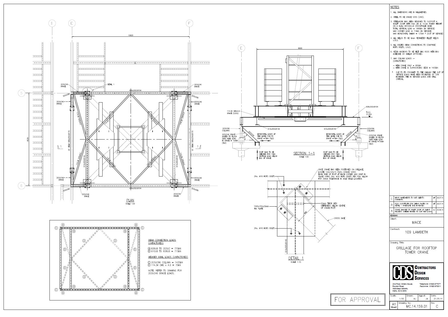
The steelwork grillage design and building verification was then category III checked by an independent engineer.
Mobile Crane
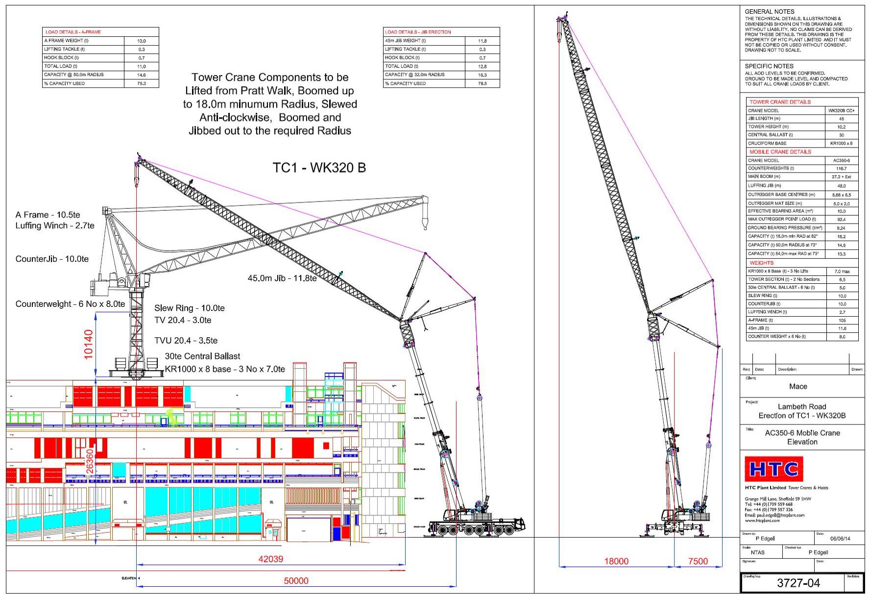
I undertook the design of the mobile crane foundations. The only workable position was for the 320 tonne mobile (a Terex AC350-6) was to situate it in Pratt Walk, an urban road between the police station and a row of occupied residential house (separating the crane and railway).
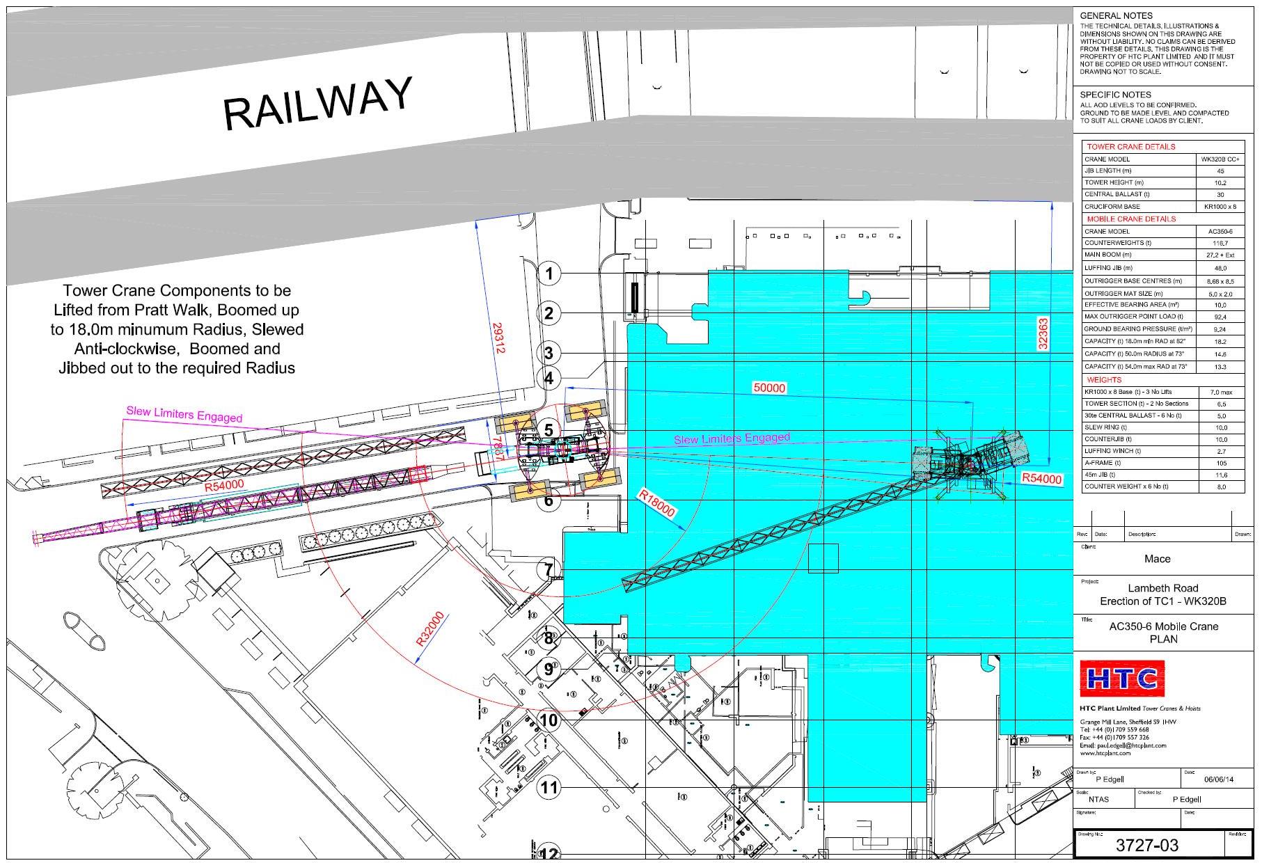
Two of the four mobile crane outriggers I chose to position over basement walls of the existing building. This gave a direct load path of the load into the raft foundation of the building.
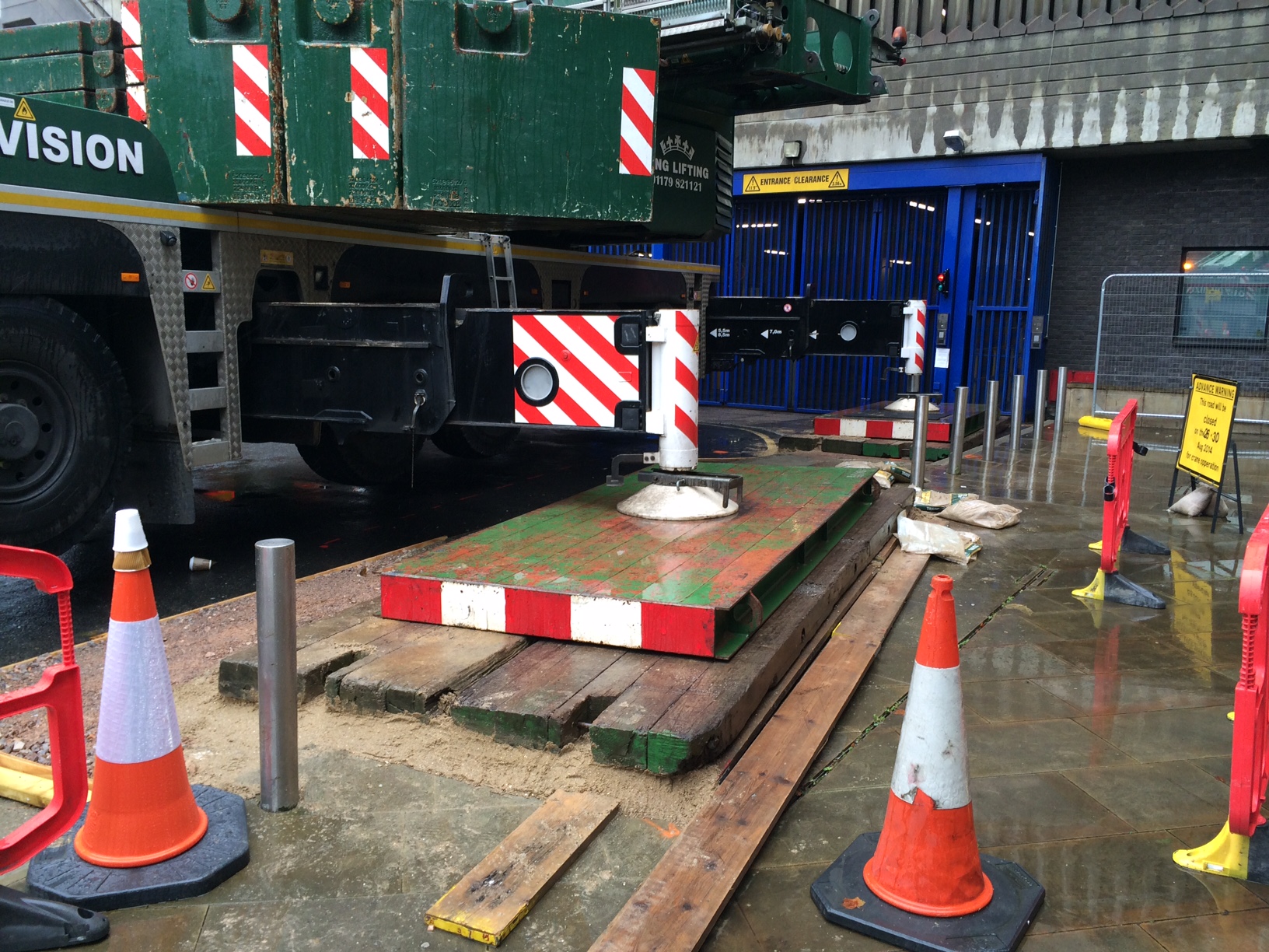
The remaining outriggers I had little choice but to position in the road. We conducted a sub-surface survey in order to identify any services near the surface. I verified the pressures from the crane in the same way as designing a foundation using C Nc, Gamma N Gamma …. The cat III checker did similar.
The Issue
Everything was signed off by Network Rail, after much stress and a presentation of our plan the previous week. The mobile crane arrived on the morning of Tuesday 26 Aug 14 and a 60T mobile erected the jib of the AC320-6.
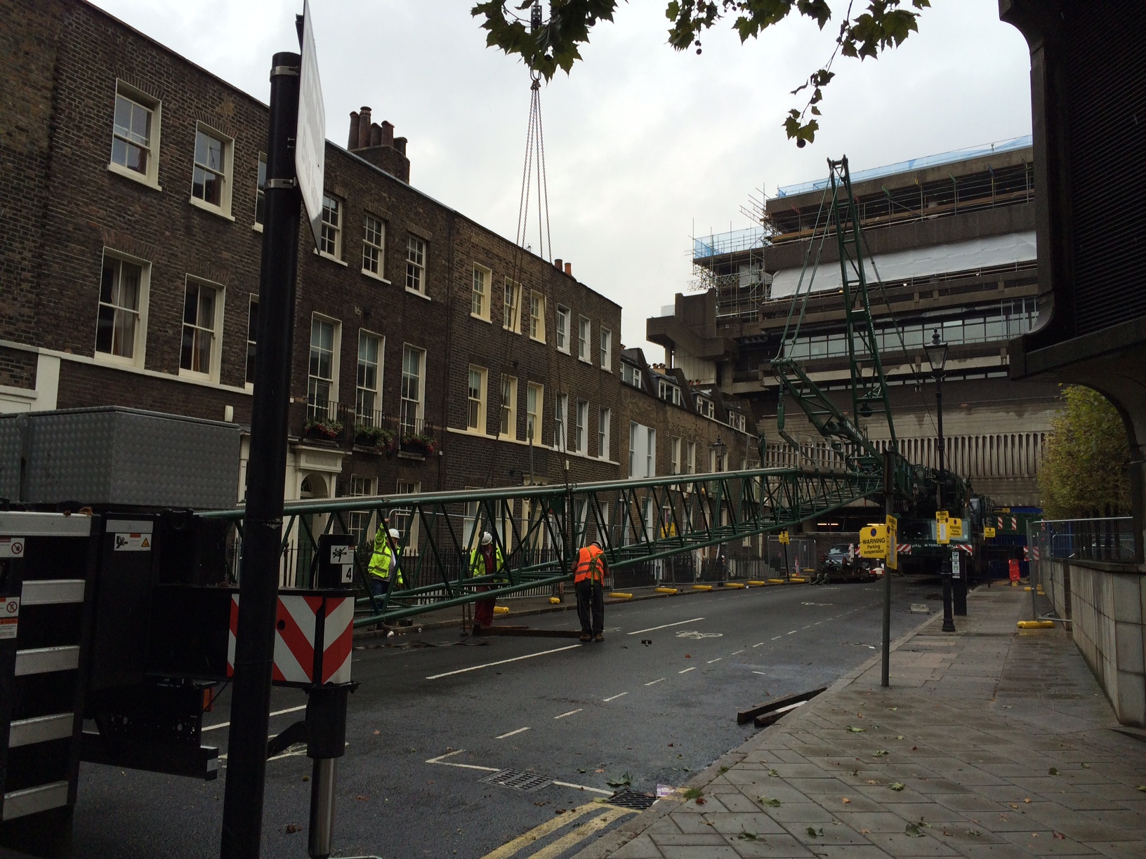
On Wednesday morning we raised the jib of the mobile and the steel wagon arrived.
Having realised all 120 tonnes of additional counterweight on the AC-320 the crane, water started to appear from beside one of the four foundations (nearest the railway). I was on site, having earlier signed off the foundations, and lifting operations were stopped immediately. The crane was slewed such that the jib could then be lowered safely back down to the ground. During this time the leak got worse and we discovered that most of the water from the broken water main was making its way from under the road directly into the police station basement, next to the LV switchroom!
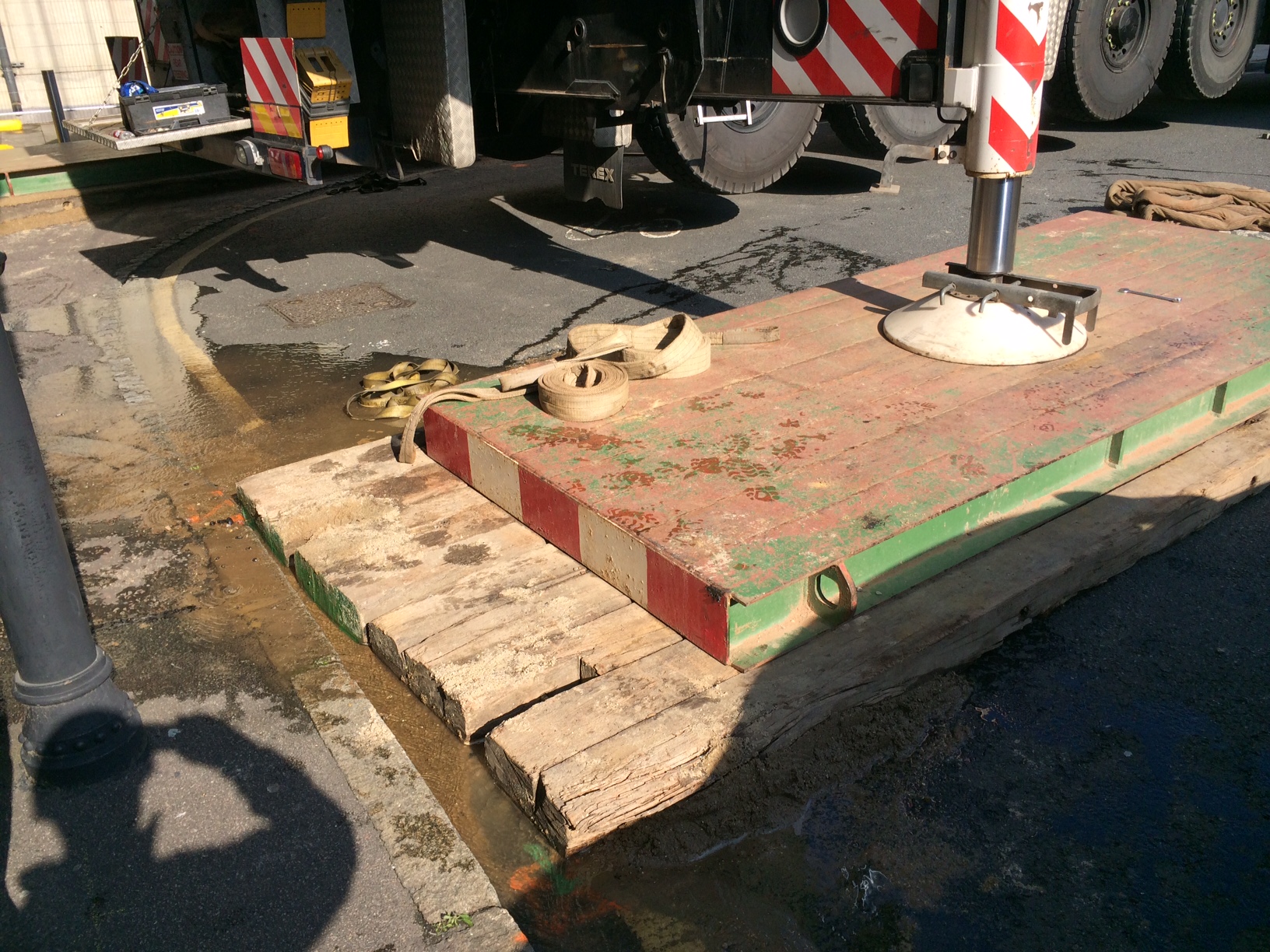
We now had a bit of an emergency and potential PR meltdown for Mace! Eventually we managed to isolate the water main and stop the leak. We narrowly avoid shutting down the LV switchroom room and the crane did not de-stabilise in any way.
Immediate Action
Following the event our immediate focus was the safety of the crane in order to ensure it did not collapse and was then the fabric of the building against water. Following this we then had to get Thames Water to site to access the leak and fix it. The Mace project director chose to keep the mobile crane on site (with incurred standing time). We had a backup road closure for the following week so chose to keep the crane on site. Without the backup road closure we would have had a 14 week delay in order to secure another road closure.
Summary
I had identified a water main 1m below one mobile crane outrigger at design stage. I had sought advice from my Mace engineering supervisor who advised that since the average ground pressures were around 100kN per meter square (10tonnes/sq m) this was acceptable and the risk was acceptable.
20140827-Mace-109Lambeth-Mobile Crane Outrigger New Matt Configuration
What I didn’t do was communicate this risk adequately. It was not on the mobile crane contractors risk assessment. The police were not aware of the risk. Thames Water were not aware of our plan to position a mobile crane on top of one of their mains.
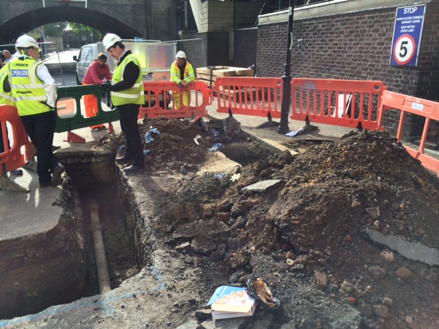
The leak was caused by a ring fracture. Although Thames Water would not say it the pipe was old but this was no excuse. I re-designed the outrigger foundation with a larger matt and used a deeper layer of sand beneath the matt to ensure pressures were evened out as far as possible. Thames Water replaced the cast iron pipe with a section of HDPE pipe. Network Rail signed off the foundation (again) and the mobile crane was erected successfully. The tower crane grillage was then lifted onto the roof. Erected and then the tower crane was erected and tested. Thankfully all this went seamlessly.
Some significant lessons learnt for me. All part of the experience! Risk registers are key and must be communicated. Get all the stakeholders involved early. If you can reduce risk in any way then do it (ie increase the size of the crane mat).
50.0892857142857 times slower than a common snail
Slipforming of the core at the South Bank Tower began back in May. The 12th of May to be precise. 12 floors to slipform, from +106m AOD to +154m AOD. That is 48m total.

Slipforming a reinforced concrete core is supposed to be fast, efficient and financially economical. PC Harringtons (our concrete contractor) sold slipforming the core at a pace of 1.5m a day, 5 days a week. So by more complicated maths this makes:
Duration = 48m / 1.5m per day = 32 working days, or roughly 6 weeks
Therefore,
Date for completion = 12th May 14 + 6 weeks = 20th Jun 14
Sadly, this date for the completion of the core was not met. We topped out today! 5th Aug 14!
Thus,
Actual duration of slipping = 5 Aug 14 – 12 May 14 = 67 working days
So,
Actual Speed of slipform rise = 48m / 67 days = 0.71m per working day
At 10 hours work per day, this makes:
Actual Speed of slipform = 0.71m / 10 hours = 0.072m per hour
or 72mm per hour
or 1.2mm per min
or 0.020 mm per second
or 20 micro m per second, on average.
A common snail has a speed of 0.001m/s, or 1mm/s, or 1000micro m/s. Therefore 50 times faster than our slipform has climbed!
As I said, the planned speed (or rate) of slipping was 1.5m per day. That makes the achieved speed of the slip 48% of the planned rate! Is this adequate? It has to be asked whether this was the most economical method of building the tower.
At the South Bank Tower we have a rare set of site conditions. The build ability of tower is generally poor, the complexity of reinforcement is high, the burden of temporary works is also high, access is limited, competition for hook time on the tower crane is high and weather conditions 150m above ground mean that it can be less than conducive to work.
I’ve decided to explore this issue in my latest TMR. What alternative systems could have been used to build the core? Should the tower have been purely steel? Additionally, should Mace have known that achieving a rate of rise of 1.5m a day was over-ambitious? And how was this reflected in the contract to deliver the slipform?
I also want to explore whether the project was influenced by the fact it wasn’t fixed price at the start, and had it been fixed would we still have taken the same decision to slip it.
Having spent the last 6 weeks inside the slip on a daily basis I can confirm it can be fraught, manic and a desperate place. There was never quiet second. PCH performed as best they could in my view. The slow pace was not due to laziness, insufficient resources or commercial will. We as Mace have driven PCH to get this core finished but the sheer complexity has denied us the rate that is normal for a slipform. Other slips on the project (10 floors high) have flown up without issue.
There is very little literature available on the rate of slipforming. Is anyone aware of any? I plan to work out the financial cost the slow slip has caused, and quantify the impact this has had to the project.
Half way to the top
The tower extension is starting to finally take shape. After a few somewhat stressful weeks getting our sub-contractors temporary works together the slipform finally launched from level 30 of the old tower.
The slipform is somewhat like oil tanker destined to have a near miss with some rocks and then be broken up! Once it is going there is no stopping it easily! And at the end of it journey it becomes redundant and is ripped to bits and cast aside!
The walls of the new tower core are only 200mm thick. This has been causing issues with fitting everything into the wall. Cover, small embed plates, climbing tubes, horizontal and vertical rebar makes for a congested beam. This has meant that whenever the slipform reached a floor level the rig was stopped for two days in order to allow all the reinforcement to be fitted. This pause also allowed us to fit bracing to the wing walls that act as sails in the wind.

The narrow walls also makes it very difficult to stop embed plates from dragging up inside the slip as it is jacked up. The embedment plates allow the exterior steel beams to be connected, with a welded fin plate, back to the core. If anyone finds themselves at a consultancy designing slipform makes the walls thickets and use 16mm vertical rebar.
Now I mentioned the near collision with the rocks and this ship. Well we, Mace, never really thought PC Harrington would deliver this tower core without fault. So surprise surprise on Friday when they informed us that two of the six corner MacAlloy embed plate pockets were in the wrong. This week we have been brainstorming to rectify this problem since there is no longer any free space to introduce the 1.5m x 2.5m embed plate into the core. See corner below.
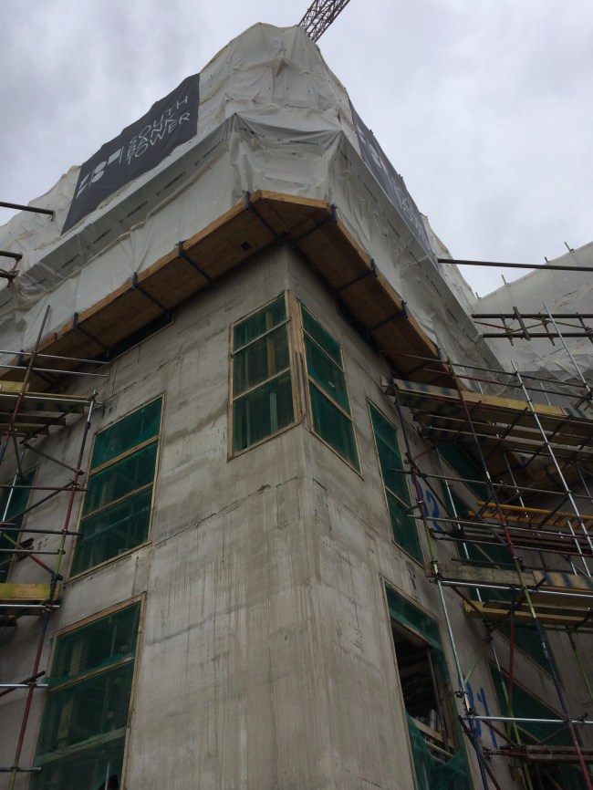
The cost to rectify this sits firmly with PC Harrington. It could, worse case, require significant temporary works to remove 1m of concrete above void such that we can get vertical rebar continuity across the embed. Best case, we can locally break out the wall to get the embed in, but the the vertical rebar won’t tie, which I’m guessing the structural engineers won’t be happy with.
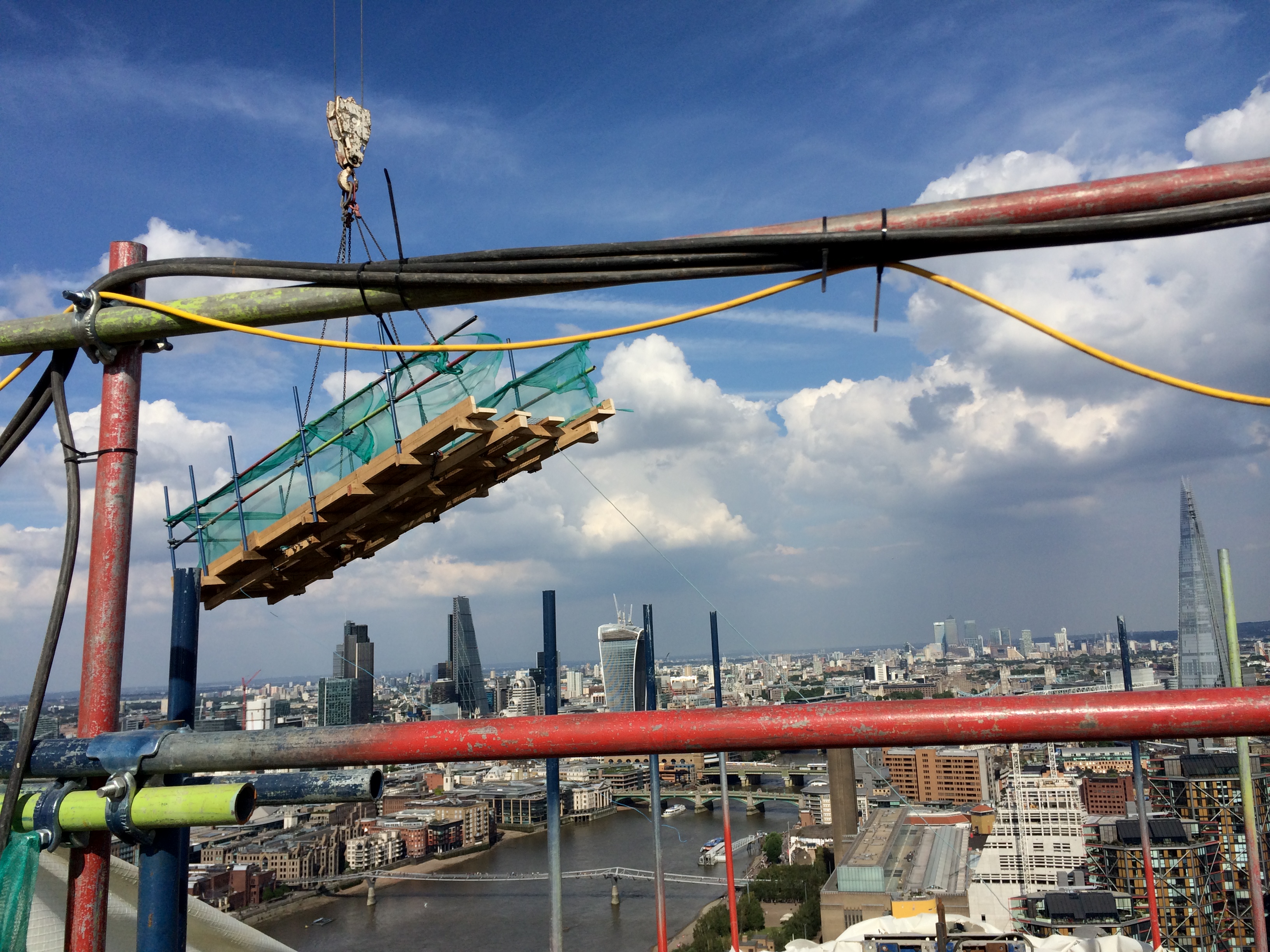
The slipform is now at the 35th SSL level which is where the four outrigger (wing) walls terminate. Therefore the rig has to be temporarily dismantled in order to allow it to continue to level 42.
Here is a picture of the top deck being lifted off. Tomorrow we will be lifting off the working deck and hanging deck together. It is a pretty precious operation since most of the lateral restraint of the slipform has to be cut to lift it down to ground.
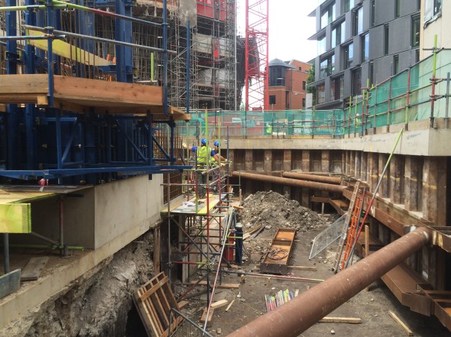
Elsewhere in the project our North Basement excavation is progressing (very slowly). The second waler is now being installed. This retaining wall is along a party wall and deflections must be limited to 10mm. Therefore the propping is very heavy. It has been on my list if ‘interesting TMR’ subjects to study sometime, but time seems to overtake!!
The focus of the project as a whole has developed too in the last two weeks. Whereas we were on a reimbursement style Construction Management Contract with the client, since there was so much outstanding design information at the start of the project, Mace have now signed a fixed price for the rest of the project. It is somewhere in the region of £200 million. However in order to make any money Mace need to accelerate the programme, and this means any major temporary works constraints made are now trying to be changed. It also means all the risk is with us (ground and all). Any sums not considered in the fixed price conversion are our of our profit. Therefore the incentive to find cost savings have significantly increased and the management of risk better managed. I’m currently working in the design of a fifth tie for the the main tower crane. This was never considered so finding a cost effective solution could be interesting.
