Archive
140 Elephant Hangers
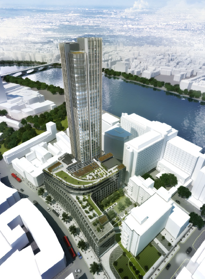
The South Bank Tower extension from 30 to 42 storeys is based upon the requirement that all vertical loads must be transmitted down the existing core to the foundations.
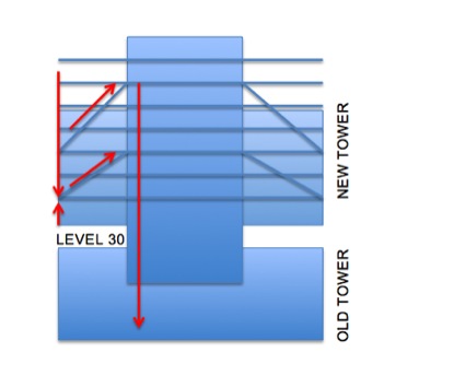
In order to do this, the floors outside of the core will be hung, supported by angled steel bars that drop down from 2 or 3 storeys above. In plan, there are three hanger locations, NW NE and SW corners (see red below). Each corner has an upper set and lower set, as can be seen above (blue diagonals).
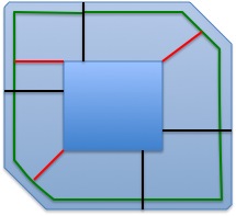
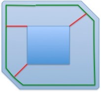
The NE and SW hangers (in red now above) each have three bars. Each bar is 100mm in diameter and is to be supplied and installed by Macalloy. Since the NW hanger supports a small floor area there are only two bars on each set. The Macalloy bars pick up load from a ring beam (in green above). The ring beam spans from the wing walls (in black above) between Level 30 and Level 35. Above Level 35 there are no wing walls and the ring beam extends around the entire building (as below).
The challenge therefore is taking the high resultant verticals loads (7600kN in disproportionate collapse = 140 elephants) that drop onto the Macalloy bars and transferring it safely into the RC core. This steel to concrete connection (the hanger) is the key element of the building and the lack of detail from our Structural Engineer has added a degree of friction to the planning and design of these elements (ref last post).
Constructability
The 12-storey reinforced concrete tower core extension is going to be built with a slipform rig. The slipform rig will not allow the corner hangers to be installed as the slip passes each hanger location. Therefore large pockets, or voids, will be left at each hanger location. Over the past month I have worked on the size of each pocket, what infill (or strengthening) is required around each to ensure the temporary stability of the tower, as well as the sequence of offering the hanger into the building and making good.
The general sequence is
1 Slipform launches from Level 30
2 Slipform leaves pockets at each hanger location (six in total)
3 Floor plates internal to the core follow the slip with a 3 floor delay
4 Slipform reaches Level 42 and is dismantled
5 The floor slab adjacent to each hanger is post tensioned, once the concrete is up to design strength.
6 Access is now possible to the hangers with the crane and the hanger is installed.
7 The Macalloy bars are attached and can suspend the steel frame exterior to the core, and later composite slabs.
The Steel to Concrete Connection
The principle of the corner hanger is to resolve the diagonal Macalloy force into a vertical and horizontal components.
The horizontal force component passes along post-tensioned cables that are anchored within a 400mm thick slab. Macalloy rods are planned to be used (not confirmed) and they will lie in the middle of the slab with no change of eccentricity. The PT slab is heavily reinforced to allow the tensile loads in the tendon to pass right through the entire core slab. Outside of the PT slab the floor is only 200mm thick.
The vertical component employs both bearing and shear keys (within the hanger) to transit the vertical compression into the walls of the core. The shear key uses three 350x350mm SHS sections (filled with grout) to engage the concrete within the walls. The key issue for us is maintaining wall reinforcement continuity into the hanger.
The way we plan to do this is by leaving couplers accessible on the edge of the void as the slipform passes. The corner hanger will be offered up in two phases. First the inside plate, with SHS sections, is lifted and positioned. Then the rebar is fixed within the hanger (and attached to the couplers left in the walls), the outside plates are welded on, and finally the hanger is filled with concrete.
The risk here is that air pockets might form within the hanger and this will significantly affect the bearing ability of the hanger.
The Issues & resolutions
- Size of the void
o We have opted to weld the hanger on site. This limits the size of the void since the lapping of rebar will happen inside, instead of outside the core. However the quality of the weld may be reduced. My input was to conduct prelim analysis of the viability of options an then a detailed examination to highlight issues to the Struct Engrs.
- Rebar displacement and continuity inside and around the hanger.
o The SHS sections block horizontal and vertical rebar. The base plate blocks vertical rebar.
o Therefore holes will be drilled in the base plate and rebar will be displaced to avoid the SHS sections. The detailed examination again identified issues and I was able to propose minor design changes.
- Temporary strengthening around the voids.
o How much strengthening is required for local and global stability? How will it affect later construction? What is the cost?
o I looked at RC strengthening, steel and proprietary systems. For global stability we are using further strips of RC to be slipped. For local stability issues the use of proprietary systems allows quick installation.
- The PT slab does not extend through the entire core.
o How will this affect the robustness of the core? Mace have not conducted any examination of the detailed design but since concerns have been raised we are now getting a Category 3 check completed on the hangers.
- There is no tensioned belt around the core at the hanger level.
o What is stopping the corner of the building bursting out from inside the core? This will be covered in the Cat 3 check.
- The Macalloy bars will elongate during construction and throw out construction tolerances.
o How do we plan the elongation and pre-set required at the start of construction. Whose responsibility is it to get it right???
o Do we plan to jack (shorten) the Macalloy bars to achieve the required length later on?
o Will the cables need to be jacked in order to achieve a regular force between them?
o These issues are not bottomed out. AKT are not willing to give preset cambers, or dictate the jacking procedure which we are strongly contending. After all, it is their design and concept, not ours, to screw up!
In all, the past few weeks have been the most interesting but stressful. The slipform is now behind schedule, but has now launches and is at level 33. PC Harringtons are paying the price still for not backing up their engineering design team since temporary works were holding up the construction.
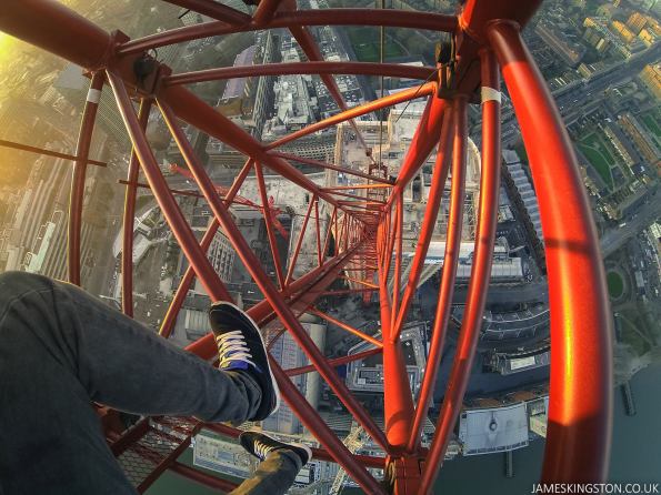
An alternative view of the South Bank Tower from Tower Crane 1
Shear loading a sheet pile wall
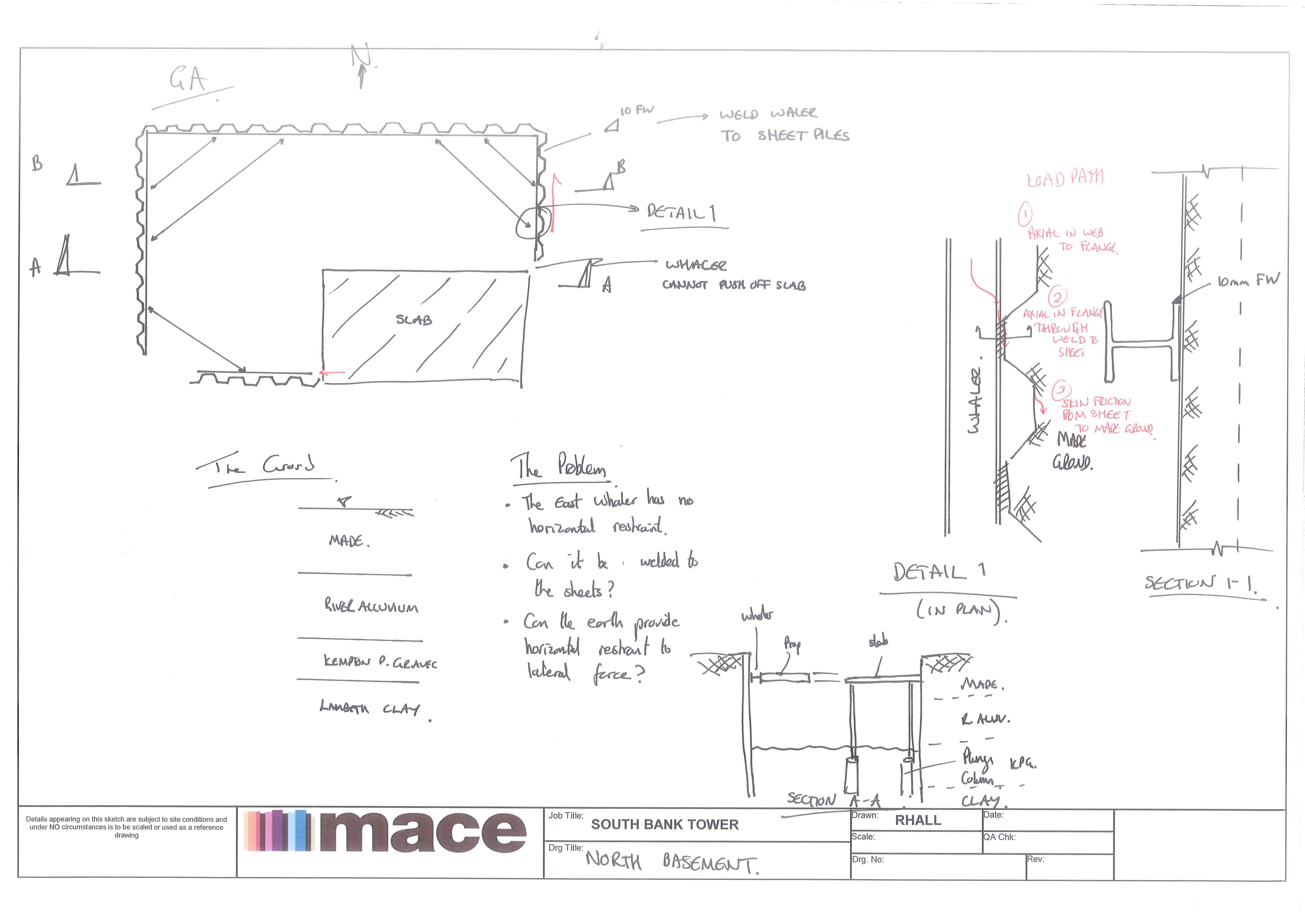
Here is a sketch our our North Basement Cofferdam. The deisgn by the Temp Works Engineer (Walsh Gp) assumed that the waling would be propped off of a slab (see sketch below). The only problem is that the waler cannot prop off the slab!
The temp work engineer proposed welding the waler to the sheets to ‘pacify’ Mace. Can you load a sheet pile wall with a shear load, ie using the sheet pile wall as a prop itself!!! I’ve yet to dig into the detail but is it even a starter!
A complicating factor is that the North Wall is a party wall and deflection must be kept below 12mm!
The piles in question are 11m long PU28-1SSP.
 T
T
Structural Engineers ______________
This week for me has been somewhat interesting.
The project director for the South Bank Tower, Shaun Tate, has gone on leave for three weeks and the duty seems pretty out the loop with what is going on. Therefore the Major Projects Director for Mace has gotten involved to sort out any problems!
Well, we have a few problems! So today the Major Projects Director sat through a temporary works meeting between Mace, PC Harringtons (sub contractor for the core sliupform), Walsh Group (temp works engineer) and AKT II (the Structural Engineers). Normally there are six of us in our weekly meeting. Today I counted thirteen at the table.
At discussion was the metal plate that attaches the 3 x Macalloy hanger rods (carrying up to 7600kN ULS force between them) to the reinforced concrete core. Now steel to concrete connections are the Structural Engineers (AKTs) bag. They (AKT) are meant to own this. Sadly for AKT they have so much already on their plate they’ve given us no time to sort this out. And by sort this out I mean determine the detail. How will this work? How do we build it! This has meant that instead of sorting the problem out at the appropriate level (meeting of 5) we have everyone at the table (meeting of 13 including the client).
Well the outcome of todays meeting was (thankfully) generally positive. The work I had done this (and last week) to understand the detail of how the rebar (in the wall) between, above, to the side and below the plate interacts with the massive hangers seemed to pay off. AKT ended up having a long list of ‘to dos’. (This includes re-designing, de-conflicting the rebar and providing some direction). The slipform does not appear (as yet) to be delayed any further than the 17 April 14( to depart from Level 30). So all is good.
What I have learnt from this is how work shy and sloppey shouldered Structural Engineers can be!!! Perhaps this is a little harsh. But I am starting to understand the friction of relationships between contractors and designers. Designers are short sighted and ignore the real world problems. Contractors only shimpf that Structural Engineers will not consider the temporary state and only ever design un-buildable structures!!
The outcome is that Mace do not trust AKT. AKT haven’t a clue how we are trying to execute the build so just choose to ignore the issue until it is escalated to such a level that they cannot ignore it! Fun fun…..
Thankfully tomorrow is Friday! My apologies for the long post. Rant over.
Progress on the South Bank Tower
As an update to what is happening on site here is a summary:
The Tower:
The level 29 and 30 slabs have now been poured.
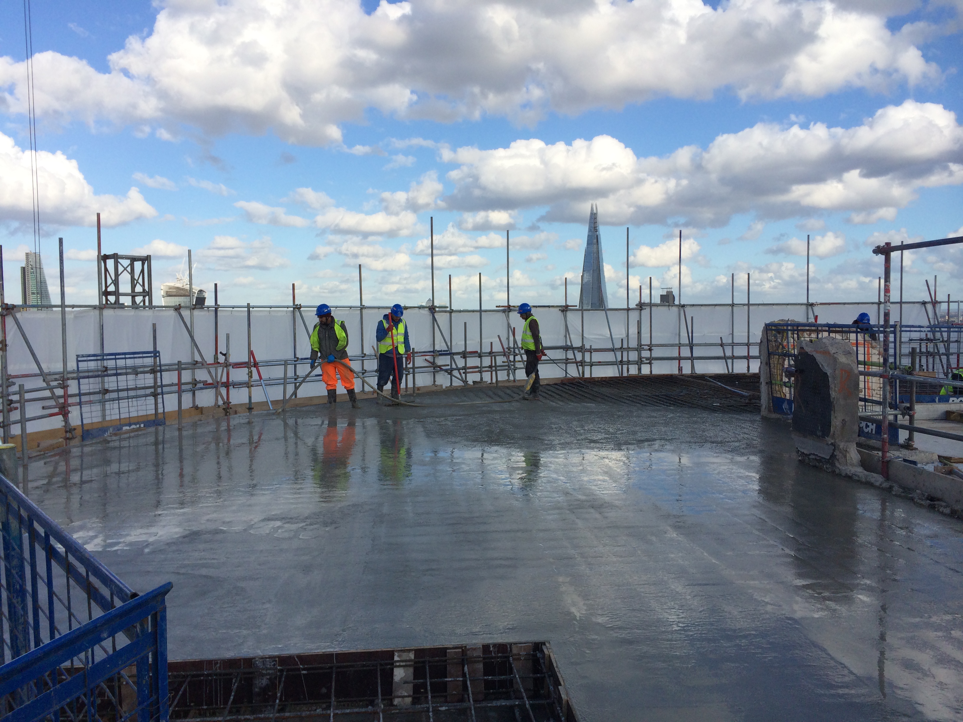 Level 30 slab being poured
PC Harrington and Slipform International are constructing the slipform rig at level 30 with a deadline, of only one week now, prior to the commencement of the slip (to level 42). This is expected to take 6-8 weeks.
Tower Crane 1 which services the tower was climbed last week to 130m without any problems. A third tie at level 28 was engaged to do this. Cladding is starting to be installed too, between levels 1 & 15.

TC1 Climbed to 130m above ground (TC2 is the small one in front)
North Basement
The north basement excavation is down to stage 1, +2m AOD. (Existing ground is +4m AOD). The first whaler is in place and the props are being installed.
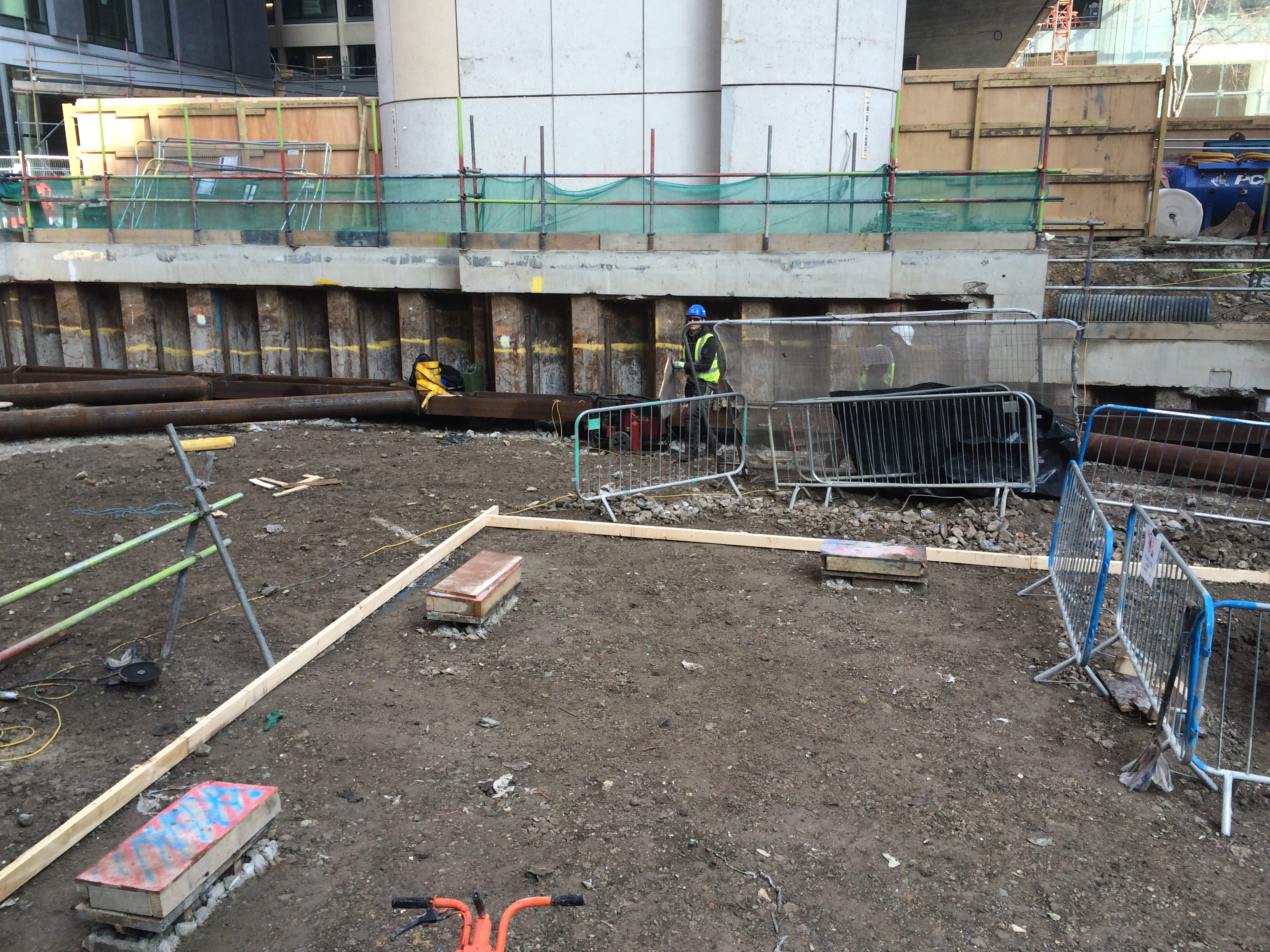
The North basement excavation
West Basement
I approved the temporary works last week and work should begin this week to install a sheet pile retaining wall. Work will then begin to construct the ground level slab prior to top down construction. (In the near-ground is the dewatering well be driven). The main issue here is that the area above the retaining wall is a logistics delivery point for concrete lorries. Agreeing a workable piling solution to allow deliveries during the excavation was the main issue and remain one to keep an eye on.

The West Basement excavation. In the near ground is the dewatering well and piles for a 10 storey central atrium core .
East Basement
In the East Basement the B1 slab beams continue to be poured in preparation for top down construction. However this is still no temporary works plan in place for the excavation as Sheet Piling UK (SPUK), who installed the sheet piles, have rejected PC Harringtons temporary works plan. SPUK were not happy with the amount of deflection in the piles since PCH were not planning to prop between the B1 and B2 slab. (The piles in a place are a PU22-1 pile, 450mm in depth).
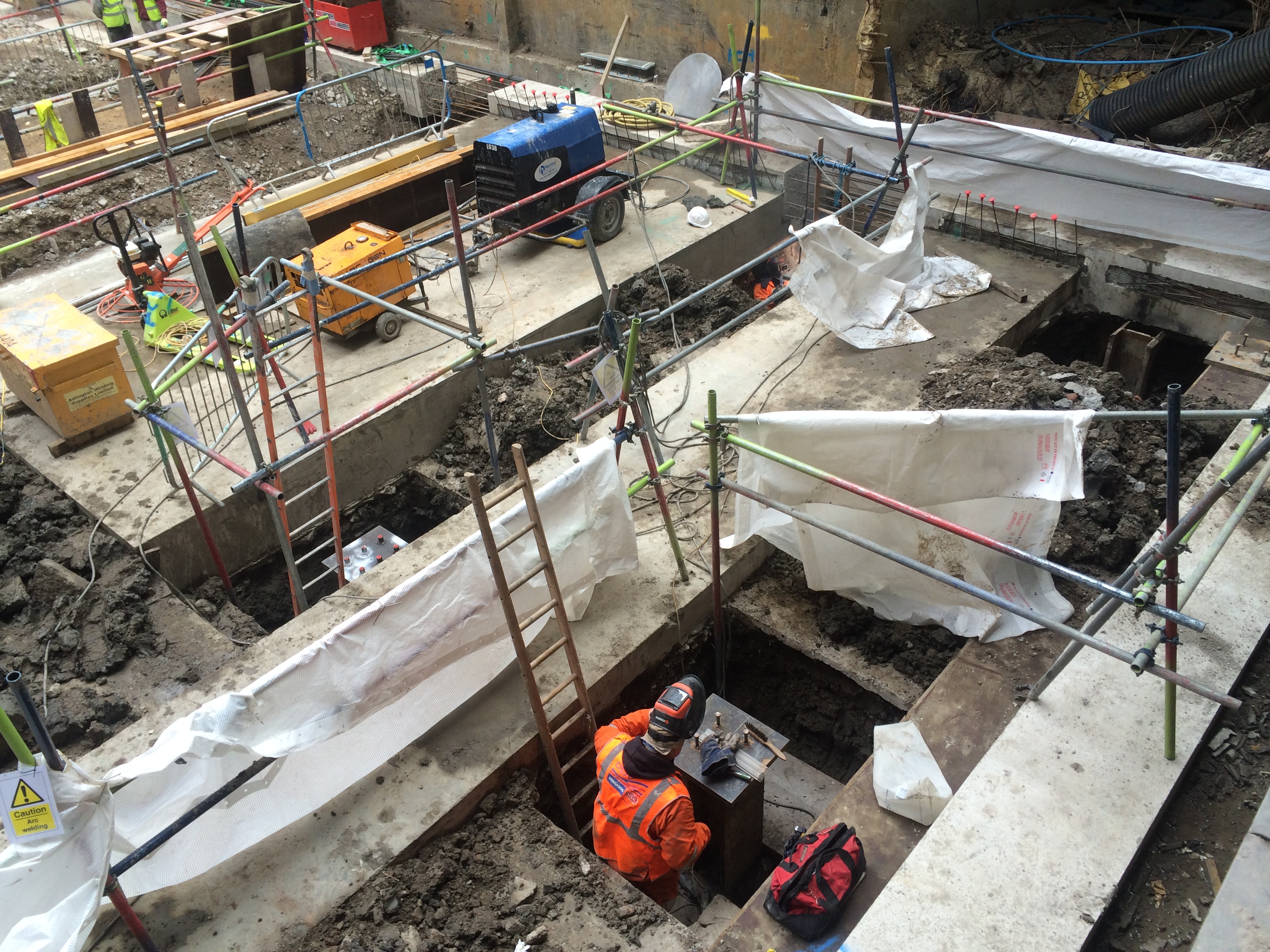
The East Basement B1 beams. The welder is preparing the top plate for a plunge column.
In summary:
It has been a busy last few weeks on site for me. Temporary works sign offs are required in all areas of the site and managing this has been interesting. There are still significant question marks about how the tower will be built. We have to leave six large pockets in the core when the slipform climbs the tower. Into each pockets a pre-fabricated steel hanger will be inserted. From this, Macalloy bars will be hung that support the 12 new storeys above (like a drawbridge works). The main issue is the installation method, size of pocket required and the temporary stability of the tower with the large pockets. I have proposed infilling some voids in order to provide vertical and horizontal load paths and this is now with a consultant engineer to model. Bearing in mind we only have one week prior to the commencement of the slip deciding this is critical. The first pocket is at level 33 so we don’t have long to decide! Other issues include how the first six floors from level 30 are built. The capacity of some existing permitter columns outside the core are near 100%. Therefore we need to engage the Macalloy hanger as soon as possible.
I am in the process of preparing a more detailed blog on this issue of Macalloys bars, hangers and post tensioned slabs. It could be a possible subject for the first TMR.
In other news I ran the Paris Marathon this weekend in 4 hr 4 mins and 43 seconds.
The Misery Line
Also known as the Northern Line!!!
I got some arrow the wrong way around!
On closer analysis and a good think (and remember to being on site) I have realised I over-simplified the problem at 5 Broadgate with the Macalloy hangers.
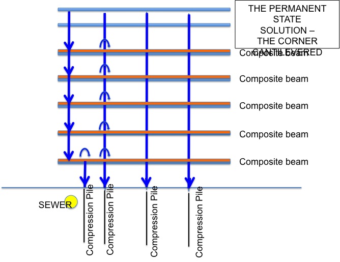
Here is effort number two. The main changes being that the Macalloys are used to pre camber the steels prior to the concrete being poured. On pouring the concrete the hangers & truss will deflect (deflection 1). The Macalloy is then released and the decks deflect further (deflection 2). Ballast would additionally be loaded onto the corner to represent cladding (deflection 3). At this point the final deflection is realised in the hanger & truss. This means that as a piece of cladding is installed on the exterior, ballast inside is removed (deflection 3 + cladding – ballast = deflection 3).
The reason for doing is, is because the designers did not design enough ‘play’ into the cladding. Once the final piece of glass is installed there would be not ballast inside and any live loading inside can be taken by the 15mm tolerance remaining.
Stage 1 – Pre camber the corner

Stage 2 – Pour the concrete in the rest of the building

Stage 3 – Pour concrete on corner is one day (all ten floors). Cure concrete. Release Macalloy. Load floor with ballast.
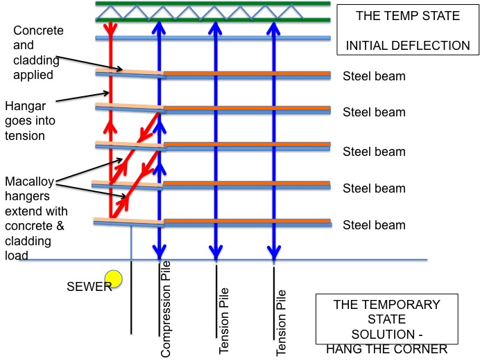
Stage 4 – Final deflection realised.

A flavour of Mace projects in the city
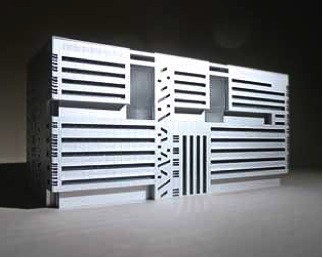
Last week I visited 5 Broadgate which is another Mace site. It is right by Liverpool Street Station and is prime banking territory. UBS is having built a 700,000 sq ft building, based on a single block form, with a gun- metal grey finish. At 12 floors it will include up to four trading floors, each able to accommodate approximately 750 traders, allowing UBS to consolidate its London trading operations into one building.
So here is the problem:
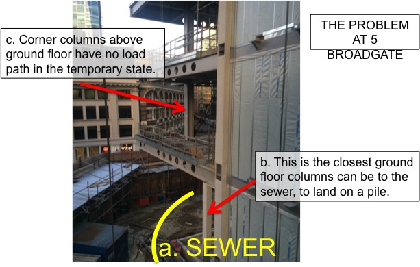 I
I
In order to overcome this issue the corner would be hung from a truss on the roof as well as Macalloy hangers on the 1st and 2nd floors.

Here is a picture of the 3rd floor with the Macalloys in use
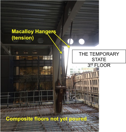
The (big) truss on the roof cantilevers out to allow the perimeter column to hang in tension and suspend the corner. Jacking was used to ensure it had ‘picked up’ the perimeter.
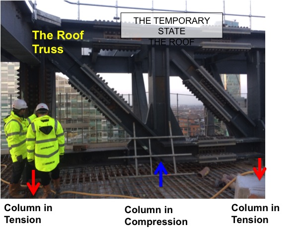
This system seems to have worked well on site. It is reasonably simple to set up and control (with jacking). Mace plan to pour all 11 floors of corner concrete at once so that there is no differential movement between the floors. The Macalloys and roof truss will be ‘stressed’ so that any elastic extension is accounted for with pre camber.
On the South Bank Tower we will also be using Macalloy cables, but ours will be used in the permanent design. The proposed force in them will be 7600kN. Anyone else got any experience with them?
It is a good idea to hit steel to steel connection bolts with a (small) hammer
So here is a picture of Tower Crane Two (TC2). It is a WOLFF tower crane with a 45m tower and a 40m jib.
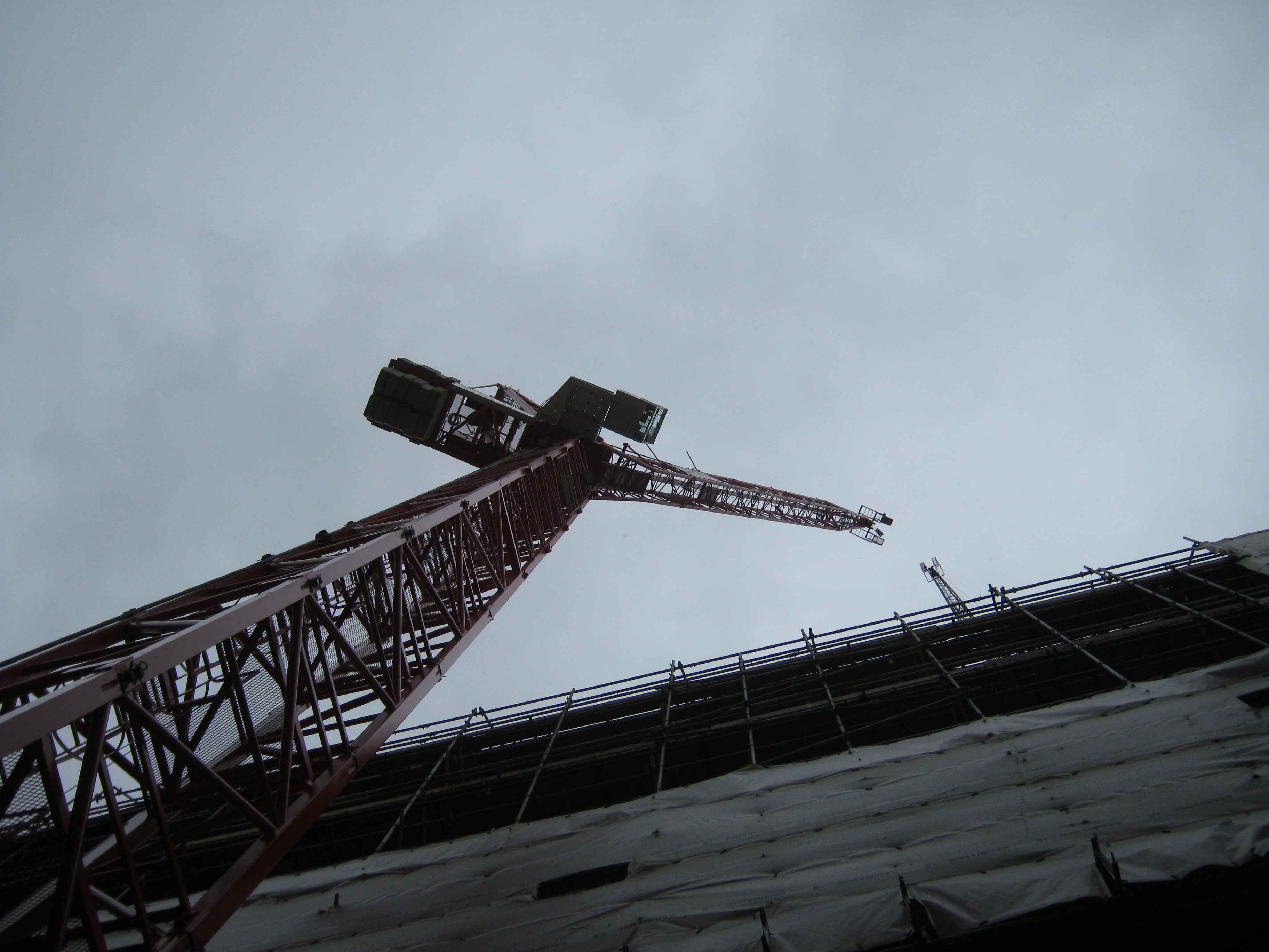 Tall Red Crane
It was installed on Thursday and Friday last week by HTC. On Thursday morning prior to the installation I went on site with Roy (the Mace Construction Engineer) and the designer (from a consulting engineers) to sign off the grillage.
The steel grillage connects the tower crane to the piled foundations beneath. Simple right? That is what I thought. So we went on site, had a look at it and signed the paperwork after some discussion.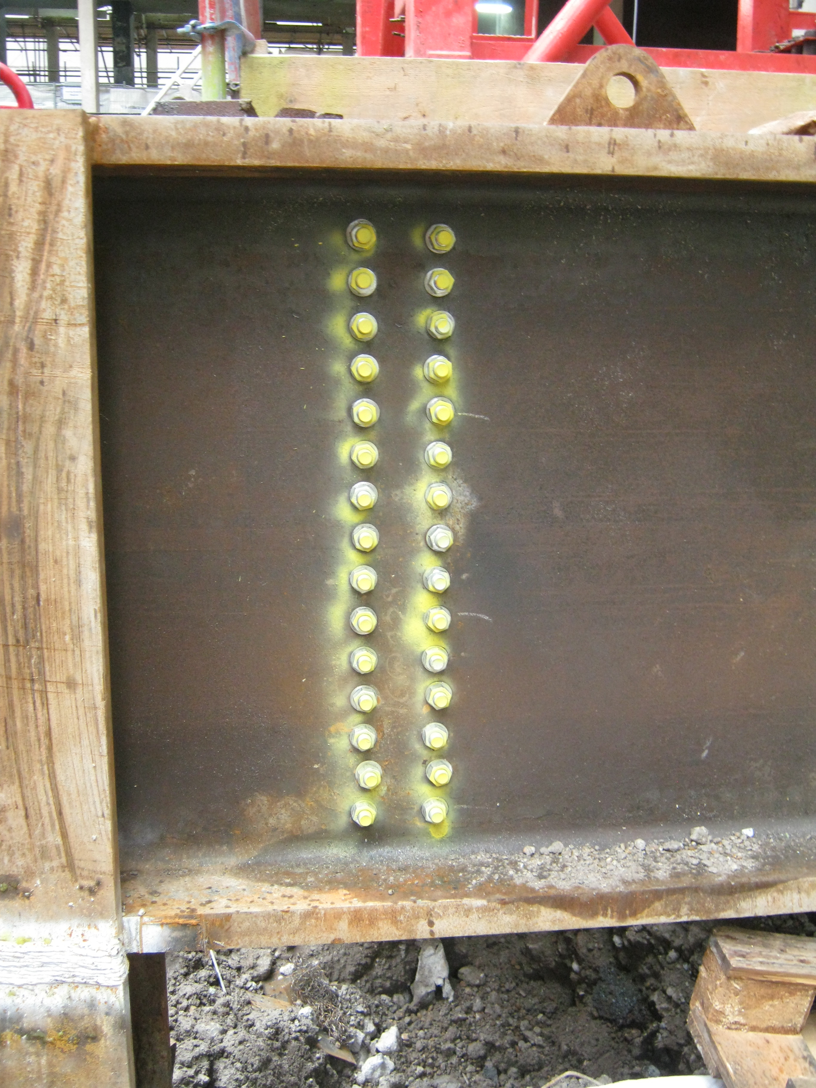
The Grillage
Well on Friday afternoon with the crane built and the load test about to start, the HTC inspector just thought he would check the bolts on the grillage (sprayed yellow in the picture above). Technically doing this was not in his remit, but he thought it wise to give them a tap with a hammer to see if they’d ‘ring’ (tight) or see whether they were loose (and don’t ring).
Well, many didn’t ‘ring’! In fact maybe 5-10 (of 240) were positively loose and perhaps 50% could be tightened further with a long spanner! Queue phone calls to the Construction Manager, Sub Contractors and me! The questions being:
1 Why are the bolts loose?
2. Who tightened the bolts?
3. What torque should they be?
4. Who signed off the grillage?
Since Roy was not in the office I found myself answering these questions. It turns out the answers were:
1. They were not checked, or re-checked.
2. The sub contractor PC Harrington responsible for the grillage sub-contracted the fabrication to DAM Fabricators. DAM didn’t check the bolts.
3. There is no torque. They had to be tight (manufacturers guidelines)! I think this means a man/woman hanging off of a spanner. As I understand it only friction bolts usually need a torque.
4. PC Harrington, Mace Construction Engineer, the Lifting Operation Manager for Mace.
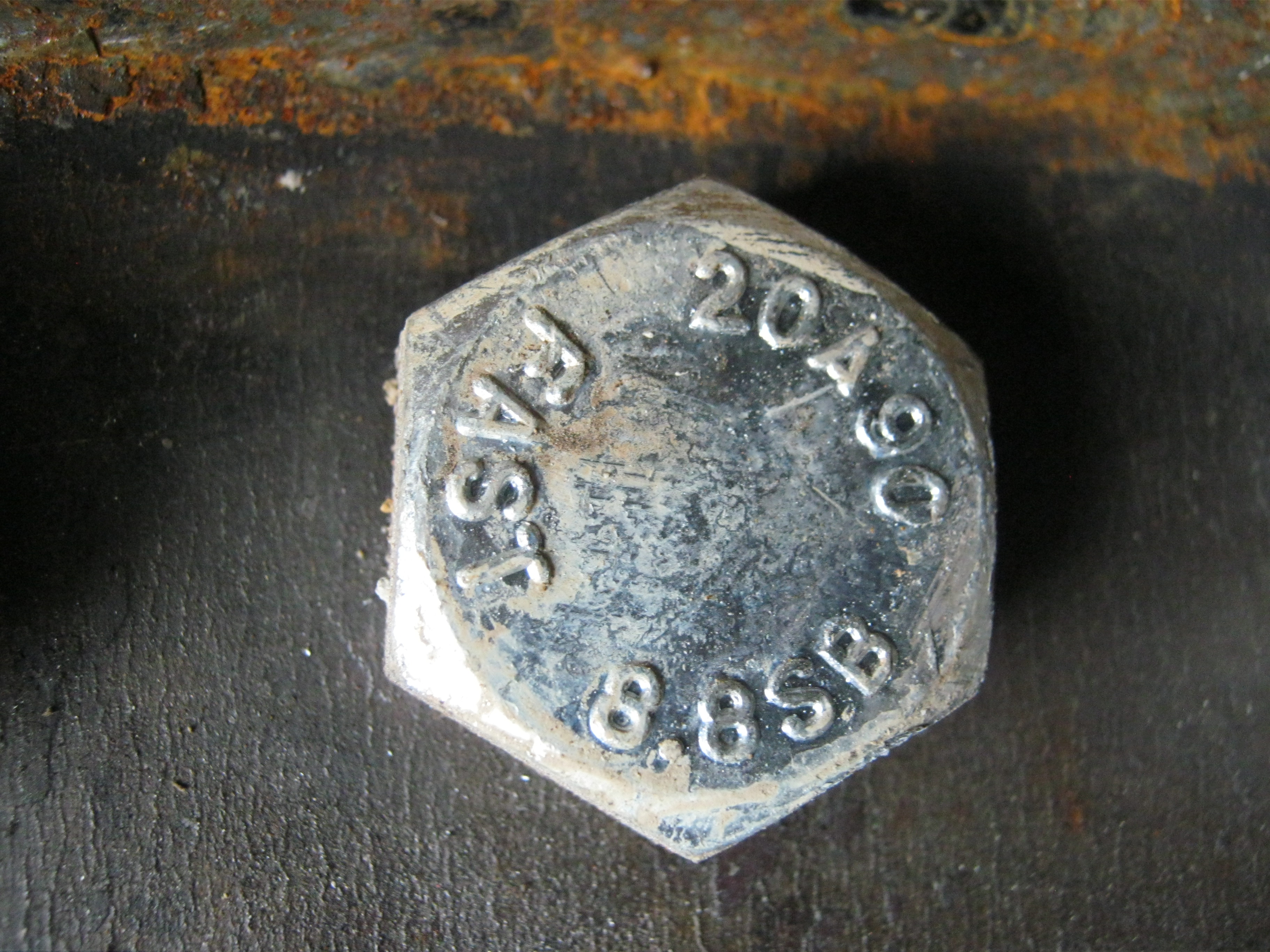
The bolts in question
So what is there to learn? All sub-contractors need to sign off their work (DAM were responsible for the bolts and they had no sign off directly to Mace); Sub-contractors need close supervision (no surprise there); Hit bolts with a hammer to get an idea of how tight they are; And finally understand what checking procedure has been used prior to you checking something.
Have I missed anything???
The key question I haven’t answered to myself is whether we (Mace) should have done a random check of bolt tightness? You chould say yes, but then we’d have a lot of other bolts to check too. I guess it’s all about the risk associated with that particular bolted connection!!!
Have you got a spare £2,915,000 for a 3 bedroom apartment?
I started last week on the South Bank Tower in London with Mace Group. Normally as PET students we work with a principal contractor that will actually do some construction themselves. Not so with Mace. As a construction management contractor, they are the principal contractor but all works are sub-contracted. With staged tendering throughout the project this means the client gets the best deal (theoretically).
What does this mean for me?
Will I get enough experience to get through CPR? Well I believed so before the attachment and I still do so now one week in. The post I have assumed is Assistant Construction Engineer. The Construction Engineer and I are responsible for all temporary works on the site, and also all Mace sites south of the River Thames including the Tate Modern extension. My principle focus is the Tower, but as with all sites there are lots of problems that need temporary works input.
Some background to the site.
CIT Group purchased the South Bank Tower in a joint venture with Jadwa Investment (a Saudi investment company) in June 2010. Since then KPF were contracted as the Architect and Adams Kara Taylor as the Design Engineers.
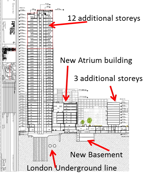
Works include a 12 storey extension on the existing brutalist designed 30 storey reinforced concrete tower block built in the 1970s by John Laing Construction Limited. This will be mixed office and residential space. Apartments start from £900,00 for 1 bedroom. The podium building (with commercial space) at the base of the Tower will have a 3 storey extension. There is a new basement, as well as a link span between the podium and the Tower.
Towards the middle of next month J Coffey (sub-contractor for the core reconfiguration) will complete all works up to level 30. This will allow PC Harrington to setup their slip forming rig, and hopefully start slipping at the start of April.
The designers (Adams Kara Taylor) have not designed for any temporary states during construction. They only ‘do’ the finished article and check temporary works plans as satisfactory. So, on my plate I have the erection of Tower Crane 4 (TC4) on level 42 to plan once the slip is complete, tying Tower Crane 1 (TC1) to the core at levels 28 and then 34, the temporary works on the basement (that is remarkably like Ex Cofferdam), core alterations to the podium buildings to consider, the foundation plan for tower crane 3, and the grillage design for a crane on top of Lambeth Met Police Station.
So in conclusion:
I understand this is a different approach I am taking to Phase 2, as I am not directly managing a task, but there is plenty of opportunity for me to do this later in my 10 months. Right now I am learning; the complexity of the project, the real engineering language that civilians use, applying my understanding of engineering and attempting to do so in a time efficient manner.
