Archive
Slope Stability – Safe or not safe?

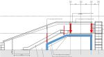
Figure 1 – 45 degree slope with 80T crane surcharge
Whilst wondering around site during my first couple of weeks I couldn’t help but notice the slope in the picture situated in River Terrace Gravels. Having now read the GDR I know the design phi dash of the River Terrace Gravels to be 33o. Therefore a design angle of Beta at approx 60o. When I queried a couple of the site/section engineers the response was that they always cut a slope at 45o and then step it if it is a larger slope. The layer below the River Terrace Gravel is London Clay and I would agree that for the short term in clay this would be sufficient, relying on the undrained shear strength. However is the design of 45o in the River Terrace Gravels acceptable?
Firstly a slope cut at 45o would still suggest a safety factor of 1.3, assuming that the pumping of ground water has reduced the ground water regime profile of the water level to below any slip surface. There is a sump reducing the water level to approximately 3m below the toe of the slope, so I will make this assumption.
I modelled this case in Geo5 (Figure 2), producing a result of instability. Geo 5 was showing failure in DC2 but not DC1. This is because DC2 is more conservative where a gamma factor of 1.25 is applied to the tan phi dash, reducing phi dash to 27o. As this is a temporary load case and we know phi dash will not be as low as 27o is this suitable for a temporary works solution?
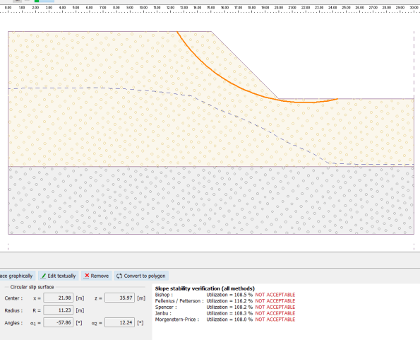
Figure 2 – Slope modelled on Geo 5
Moving on – As you will see in my photos there is a crane (80T) operation at the top of the slope, therefore once you take this load and factor by 1.3 (NA to 1990. NA.A1.2(C)) and re-model in Geo5 you can see it fails with a larger rotational slip. The crane is in fact sitting on a 400mm deep concrete blinding but I cannot model this without Geo 5 ignoring STR failure in the concrete pad. If I ignore the pad then obviously the situation is worse but the principal the same.
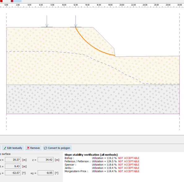
Figure 3 – Slope modelled with surcharge
The gamma factors in the Eurocodes are there as guidance and therefore I would argue temporary works is the ideal time to reduce them if considered safe to do so by the engineer (allowing for other factors). Is this an example of just such time when the ground seems to be behaving as expected or is this too great a risk. However currently there is no temporary works design for this slope and the surcharge inflected by the crane; so I would suggest it is too much of a risk!
One Nine Elms – How not to design a structure
So, hello everybody. I hope everyone is settling in well and the Australia lot are not too sunburnt. In order to not bore everyone by just regurgitating AER 1, I intend to give you a brief overview of my site and then discuss the main issue with the project.
HEALTH WARNING – it’s a long one, sorry.
One Nine Elms – Multiplex
I am currently a site engineer for Multiplex on the One Nine Elms project. Multiplex have been brought in by Wanda (the client) after a number of contractors had walked away, being unable to agree on price and the project was showing little progress being almost a year behind schedule. The current contractual arrangements are slightly confusing but in essence everyone is currently under contract directly to Wanda. Second London Wall (Employers Agent) are the clients advisors and Multiplex under a Construction Management contract, but with not direct control over the sub contractors. All this makes for a confusing and rather inefficient site however, Multiplex will be moving to a Design and Build contact in June with the client becoming Second London Wall. I suspect this will be a future blog or TMR once it becomes a little clearer.
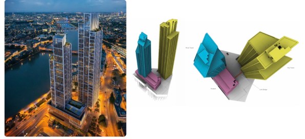
Fig. 1 Architects Impression (Left) and Superstructure 3D (Right) – notice the lack of St George Wharf completed in 2014
The site is the redevelopment of the Market towers, two 23 storey RC towers completed in 1975 and demolished by McGees in April 2015. Piling and groundworks began on site during the demolition and is not likely to be complete until the early 2018 which I will elaborate on below.
Superstructure
The superstructure consists of two high rise buildings referred to as the City Tower (yellow) and the River Tower (blue), the towers are linked at the first floor with a link bridge via a podium (purple). The City Tower is 56 storeys assigned for residential occupation, with the River Tower being 42 storeys with the upper levels being for residential occupation and the lower levels assigned as a hotel along with the podium. The structural concept for both towers is typically post tensioned reinforced concrete solid slabs supported by composite concrete encased steel columns and a centrally located reinforced concrete core. The reinforced concrete core along with its buttresses provide the lateral stability to the building, floor plates act as diaphrams restraining columns and transfer lateral loads to the core.
Substructure
There are two basement levels across the whole site with a third level between the two towers. A 1750mm combined sewer runs through the middle of the site which splits the substructure in two. Groundwater cut off is achieved by two 800mm diaphragm walls boxes either side of the sewer which have a toe depth in the London Clay. The foundations supporting the Superstructure consist of 256 compression and tension bored piles acting in conjunction with the raft at B2 level. These piles vary in diameter ranging between 1800mm and 900mm with the toe in the Thanet Sands. Due to the proposed construction sequence some of the piles contain plunge columns.
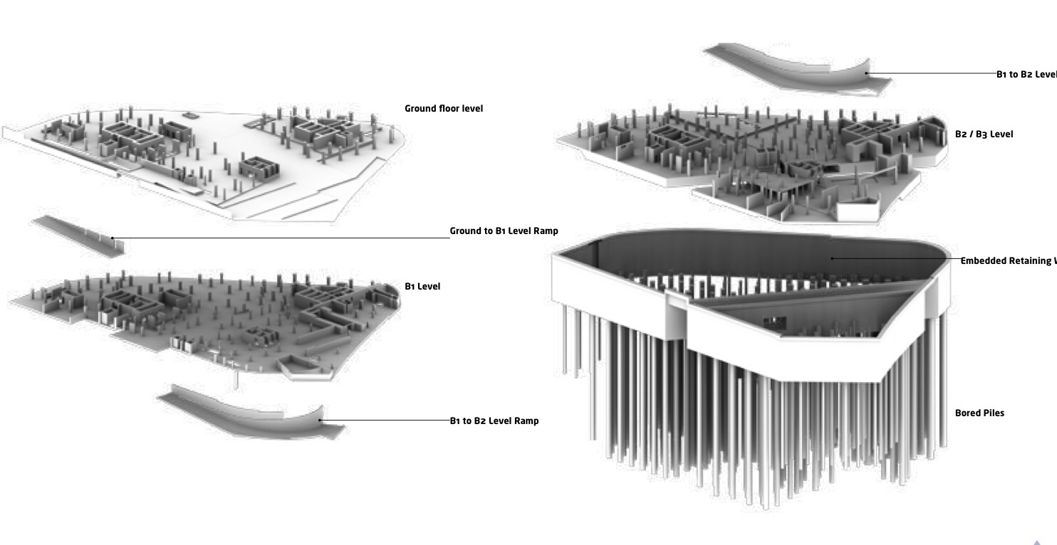
Fig 2 Diagram of substructure
Ground Conditions
The ground below the site is typical of London and consists of Made Ground (depths between 1.1m – 4.90m), Alluvium (depths between 4.5m – 9.5m), Kempton Park Gravel (depths between 7.5m – 23.0m), London Clay (depths between 22.0m – 31.5m), Lambeth Group (depths between 10.5m – 16.2m), Thanet Sand (depth between 9.2m and 13.0m) above the Newhaven Chalk Formation. Groundwater is between 3.7m and 6.4m deep and is known to fluctuate, with the level of the Thames. Fig 3 below shows the Lithology along the route of the sewer, there is a scour Pingo feature in the East of the site and it can be clearly seen on the right below.
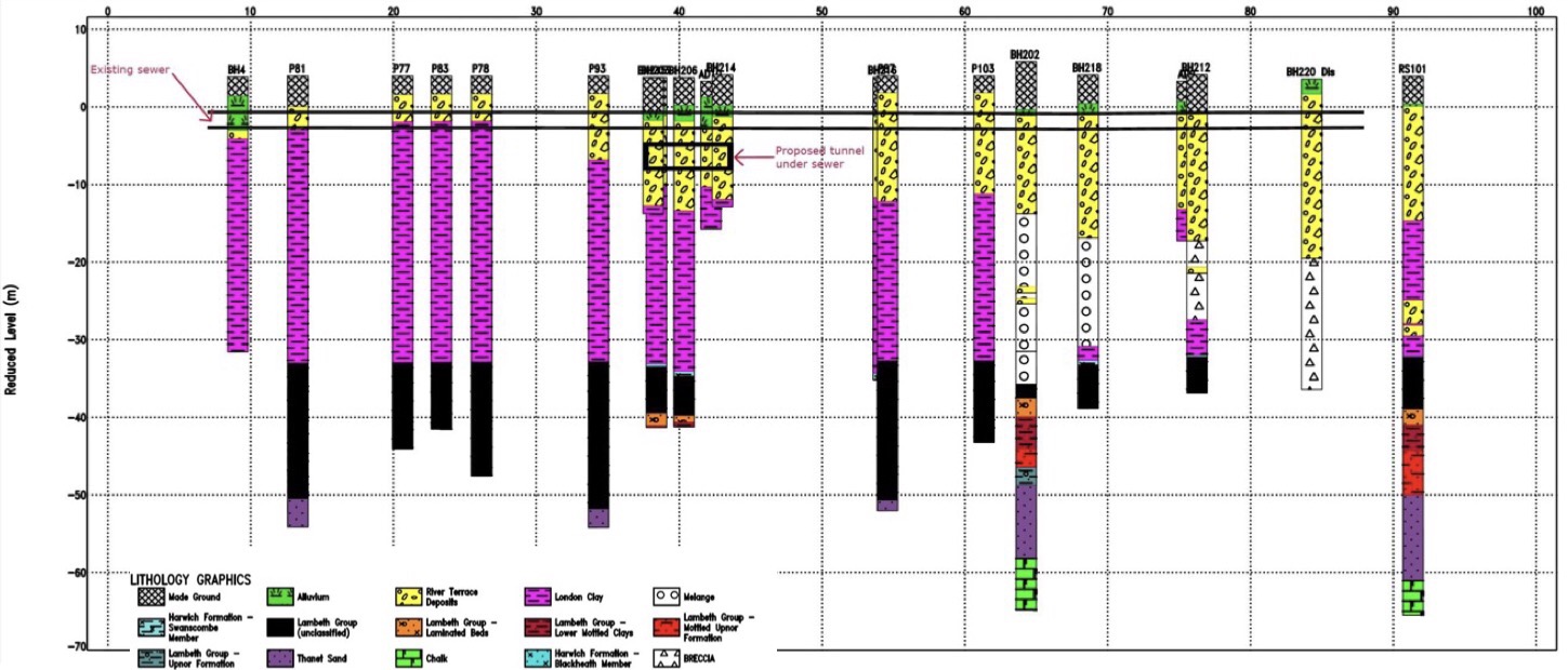
Fig 3. Lithology along the length of the sewer
Construction Sequence
The original squence and design was for top down whilst constructing the two tower cores on a number of plunge columns simultaneously, in theory reducing the project duration. However due to issues with the sewer which I will outline below the sequence has gone to pot and now looks like bottom up around the River Tower and top down around the City Tower.
Sewer Issue
As mentioned above, the site sits directly over an existing Victorian masonry combined sewer. The Market Tower (old building) basement structure spanned over the sewer and was supported on piles either side with a 1.3m to 1.5m exclusion. Where superstructure columns landed within the exclusion zone a 2m deep slab transferred the load to piles either side. The same solution has been proposed for the new building – First error!
The option to construct a new sewer around the perimeter of the site was tabled at a cost of around £2 million, this was rejected by the CEO of Wanda. The reason cannot have been for cost. The 150m of extra diaphragm wall, two 2m deep steel transfer beams, fabricated out of 200mm thick plate which take down a main load path over the sewer and the 1000 tonne crane to lift them in will cost significantly more. Mental!
Having made the decision not to construct a new sewer, the next worst possible decision would be to let the achitects put the taller of the two towers where the scour feature is. Hence requiring a greater number of larger piles to carry the larger loads in more difficult ground, which raises issues of conflicting with existing piles….. You guessed it. The core of the 56 Storey City Tower is smack bang over the sewer and in the worst ground. Not only this but due to load exclusion zone the two huge transfer beams mentioned above are now required. Mental 2!
So you would think with everything mentioned above, a detailed internal monitoring system of the sewer would be wise to compare displacements to expected values….. Nope. Wanda decided it didn’t want to waste money installing a detailed monitoring system during the demolition (against the advice of pretty much everyone involved in the project), instead opting for an Invar rod and tube system on the crown of the sewer. These are cheap but have numerous disadvantages, such as not being very accurate being suceptible to temperature change and being surface laid are easily tracked over and disturbed by plant.
Analysis was conducted to estimate the sewer movement during demolition (heave due to a reduction in effective stress in the clay) and settlement during the construction of the D Wall and permanent structure. This analysis predicted vertical sewer deflections of +27mm during demolition, +63mm during excavation and on completion of the superstructure of +28mm (que a JM rant on accuracies in geotechnics). An interesting point here is that the new structure makes a better job of spreading the load across the footprint of the site, hence the heave remember JMs voids ratio v effective stress.
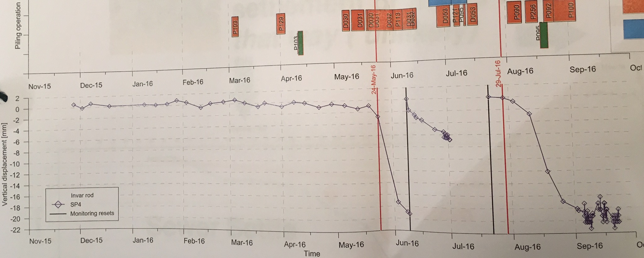
Fig 4 weekly Invar Rod monitoring results overlaid with activity, piling (green), Coring (orange)
As can be seen in Fig 4 above, the coring of existing piles for construction of the D wall seems to suggest about 50mm of settlement, combined with 200mm of settlement known to have occurred before 2013. This puts the sewer way beyond the allowable strain stated by Thames Water (TW). The large jumps and the rod resets (black lines), raise the question of the reliability of the results but if this is all you have then it has to be trusted.
As a result of this settlement TW have imposed a 7.5m load exclusion zone either side of the sewer, until its integrity can be guaranteed . This effectively makes the completion of the piling impossible and blows the programme to bits. The current solution is to line the sewer with a steel liner, this maybe jacked down the sewer or lifted into place by cutting out the crown. These are subject to TW approval of the method. This work will take 30 – 40 weeks which is a direct delay to the project, as the effected areas are on the critical path and at an unknown cost (this will be a subject of a future blog). On top of this the D wall and key piles for transfer beams can not be done until after the sewer remediation. The clamshell rig leaves site for another job next weekend, leaving an incomplete GW cut off and a fairly large bentonite farm in the only area where work can continue. This is a pretty big issue, these rigs normally require a big lead time, booking for 9 months or more and have a significant establishment cost. Due to the depth required and then associate problems on achieving interlock due to tolerances, a secant wall solution may not be possible. The resultant of this is Wanda considering purchasing their own clamshell rig at a cost of £1.2million and MPX under considerable pressure to demonstrate to the client that are worth there margins.
Sorry for the long one, I’ve probably glossed over some vital information so fire away.
Bouncy Bridge
Good news! If you are a person who takes to train to Luton airport and have to deal with the shuttle bus to the airport terminal, worry no more. The owners of the airport have realised that the fact you need to take a bus to the terminal is putting off people travelling to their lovely airport and are doing something about it.
Arup have been working on the design for an automatic shuttle system (MPT – Mass Public Transit); think North to South Terminal at Gatwick Airport. Which will whisk you from the National rail platform up an escalator to a footbridge and into the Airport terminal in 4 minutes.
You may have seen an article in the press/ NCE magazine.
https://www.newcivilengineer.com/latest/115m-luton-airport-rail-link-tender-out/10017758.article
https://www.newcivilengineer.com/latest/details-revealed-for-luton-gateway-bridge/10017973.article
Network Rail Footbridge
As part of this project, over the last 3 weeks I have been working on the design of a steel footbridge structure which will span over the rail tracks at Luton Parkway Station. The bridge will connect into two lifts (which are self-supporting) and five escalators supported by bridge superstructure.


The bridge itself is a continuous steel vierendeel truss (I had to look into vierendeel trusses to realise that a vierendeel truss isn’t actually a truss, but this point is probably for another blog). The bridge is supported on three pairs of portal frames that sit on the station platform supported by piled foundations. All sections are welded rectangular steel sections. The shape of the portal frame is unconventional and is driven by the architects to maintain as much clear space under the bridge to increase sightlines. It is this shape which is starting to cause problems.
There a number of loads and combinations acting on the portal frames however the main variable loads are from the bridge and the escalators. Which act to destabilise the portal frame. Its easy to realise that the shape isnt the best for a portal frame. As the frame is loaded at mid-span the horizontal members want to straighten an overturning moment is generated to topple over the tallest column.
-
- Main Variable Actions on the Portal Frame
-
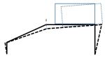
- Deflection of the Portal Frame
3D modelling
I have generated a model of the bridge in GSA (design programme written by Arup) to compare against my hand calcs and to model the 3D element of the structure. the age old problem of whether to model the frame with pin supports or moment connections raised its ugly head.
Modelled with pin supports deflections at the top of the escalator are about 40mm. Although no one can tell me what the allowable deflection for an escalator is I am assuming this this is too high. Does anyone have any experience with deflection in escalators? If I fix the column supports I can reduce the deflection to what I think is a more manageable 15mm however this generates a 2MNm moment which needs to be restrained. Meanwhile, I am looking to shorten the span from 18m though this requires negotiation with the architects.
Dynamic modelling
Arup’s experience with ‘bouncy bridges’ is quite developed following from history that people are happy to talk about. Arup are responsible for the millennium bridge fiasco though I am reliably informed by tony that the engineer responsible no longer work with Arup and works at Tony’s placement.
The dynamic response of bridges has been an interesting learning curve. Eurocode 1991-1-4 states that if the wind response frequency is above 1Hz then a dynamic check need to be conducted anyway. I have conducted a dynamic analysis of 10 modes which only considers the dead and superimposed dead loads. Unfortunately most modes have frequency between 2Hz and 7.5Hz, which puts it at risk of user induced oscillations.
These are videos of two of the dynamic modes of failure. In both the deflections are severely exaggerated but they are interesting and show the movement. You can also see that the deflection is largely as a result of the portal frame. Hopefully the videos work.
The second largest movement is due to the articulation of the bridge. The bridge is fixed to the portal frame at the centre on a pin bearing which means that all lateral forces are resisted in a rather small portal frame (2.75m wide) acting in the minor axis of the section.
Next Step
The design is still developing so there is still further to go. I initially left out the floor plate from the model as I wanted to be conservative. However by including it should stiffen up the lateral movement. I have also arranged a meeting with the architects to see how we can reduce the span or even the angle of the portal frame.
Watch this space.
Airport East; Demonstrating the Ground is a Risk.
Background
Sydney Kingsford Smith Airport and Port Botany are two of Australia’s most important international gateways. The roads around the airport and Port Botany are becoming increasingly congested due to the rising numbers of passenger and freight vehicles. The Airport East Precinct project will support the development of the West Connex motorway, which will improve access between this area and Western Sydney.
Project Overview
The Contract is for road and rail bridge construction on General Holmes Drive, Botany Road, Wentworth Avenue, Joyce Drive and Mill Pond Road in the east precinct of Kingsford Smith Airport at Mascot.
As site engineer I am currently overseeing elements of the installation of a new two span reinforced concrete bridge linking the new Wentworth Avenue underpass to General Holmes Drive (GHD) shown in figure 1 and tendering for the precast bridge planks.
The site is heavily congested and restricted, an active freight railway line dissects the centre. A sewer, high pressure gas line, and canal also create obstacles which have load limits imposed on them; therefore manoeuvring machinery is posing to be a real headache. There is also a vertical limit of an obstacle limitation surface; this defines the airspace surrounding Sydney Airport that must be protected from obstacles so aircraft are free to descend without interference landing.
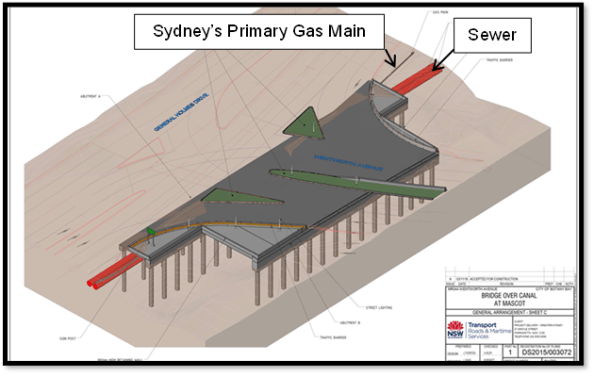
Figure 1 – Bridge Linking GHD to Wentworth Avenue Underpass
Vibration Management
The east runway is undergoing maintenance from 24 March 17 – 3 April 17 which allows the tall piling rigs to be set up. I have noticed rotary aircraft using the eastern side of the runway so have suggested that red warning lights (complying with Civil Aviation Authority Standards) are attached to the top of each of the piling rigs and included in the activity method statements.
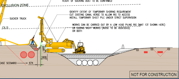
Figure 2 – Non-destructive Excavation & Sheet Piling Stage
A sheet pile wall will be installed adjacent to the primary gas main that will serve two functions (figure 2);
a. Retain the existing ground profile and allow for backfill around the gas main to eliminate any potential settlement or subsidence through piling and bridge substructure works.
b. To provide robust sacrificial formwork for the capping beam / pile cap.
Prior to installation of the sheet pile, non-destructive excavation was used to determine the exact location of the gas main and extent of stabilised sand backfill around the services (figure 3).
During the sheet piling, vibration monitors have been installed along the sewer and gas main to record vibrations which may occur. Limits of vibrations which cannot be exceeded for the gas main are 20 mm/s and 5 mm/s for the sewer. If the vibration limits do exceed this, a silent piling rig will be utilised. I have questioned these figures as I was asked to research ground borne vibration on buildings within the area and DIN 4150-3 limits peak particle velocity to 3 mm/s on sensitive buildings.
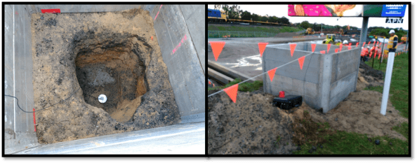
Figure 3 – Vibration Monitoring of Gas Main
The silent piler uses the ‘press in’ method, grasping the previously installed piles and establishing a reaction force from the negative skin friction and interlock resistance of the previously installed piles. Since the piles are pressed in this method does not cause any damage to the environment including neighbouring structures, assets or residents through noise and vibration.
Contamination
The project site is contaminated with poly-fluoroalkyl substances, known as PFAs. These are a group of manufactured chemicals contained in firefighting foam, they are added to improve the foams ability to smother fires. Therefore the likely source is Sydney Airport, the drainage for the airport runs through the site. The pathway and transfer of the PFAs is via the natural ground water flow through the site, and the possible receptors are workers and local residents as excavation occurs. They are a carcinogenic but are not found in high enough concentrations in the vicinity of the site to cause harm to workers.
Continuous flight augering (CFA) piling is being used due to the poor ground conditions and lack of cohesiveness of the loose, brown/grey fine to medium SAND. This method of piling stops the excavation collapsing due the concrete being pumped in as the helicoidal auger is extracted to give positive pressure to the excavation walls.
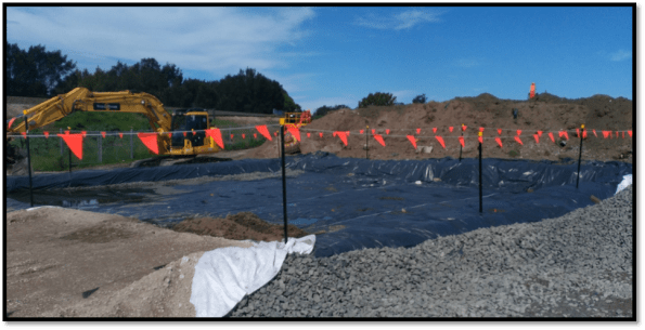
Figure 4 – PVC Barrier Layer for Spoil Heap to Limit Contamination
Excavated spoil is going to be placed in spoil heaps as to not contaminate the top soil. The PVC sheet is used as a separator and for the site to be compliant with the Australian Environmental Agency requirements. After looking at the design borehole (figure 5) for the site, I noticed the differing concentrations in PFA’s across the site. I have suggested that separate spoil heaps are created for different areas of excavation as to not waste money in disposal of contaminated waste which is has a different concentration of PFAs.
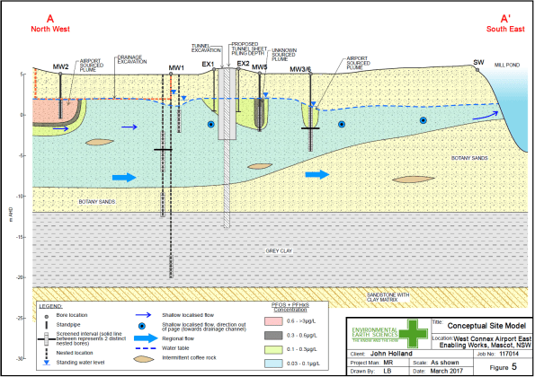
Figure 5 – Design Borehole for Site
CFA Piling Issues
As stated earlier the ground conditions are dictating that CFA piling is used. There have been some difficulties though when driving the cage into the poured concrete. Even though the water table is -3m AOD the loose, brown/grey fine to medium SAND is absorbing the moisture content of the concrete causing the concrete to cure quicker than expected. The concrete used has 240mm slump and aggregate size of 10mm (primarily to fit down the CFA tube). To overcome the issue 2m of concrete is being poured then immediately drilled out, lining the excavation with a layer of concrete to mitigate the loss in moisture content. Currently an excavator bucket is being used to push the cage into the concrete, but vibration of the cage is also being looked into. Thoughts on the use of a plasticiser?
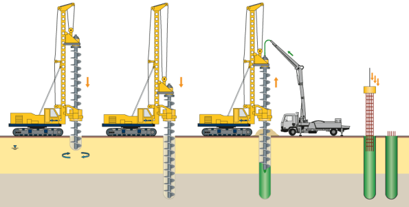
Figure 6 – CFA Piling Process
IBM Greenford – Site Visit
Overview
IBM Greenford is a large tier 3 data centre, so it has a considerable amount of M&E equipment to keep the data centre running 24 hours a day and additional parts to increase the system redundancy in N+1 configuration. IBM has their own on site facilities management (FM) team, Kirby are the subcontractor doing the construction and Atkins provide the specialist electrical support.
I have recently visited site for a meeting regarding an issue with the new pumps being installed and to familiarise myself with the installation of the Uninterruptable Power Supply (UPS) system in the new purpose built building.
Pumps
The IBM site has an open loop industrial chiller system so the pumps supply water from an open aired tank to the chiller units. The old pumps are Worthing Simpson which are no longer available and are therefore being replaced by high efficiency Grundfos pumps.


The issue is the new pump kept going out of service and the FM team believe the pump is experiencing cavitation. The main cause of the problem is unknown; the meeting was exploring the potential causes and solutions with the contractor and an engineer from Grundfos via skype. Due to the issue with the pump, IBM want the pumps to be individually tested to confirm the performance matches the specification prior to installation and commission as soon as possible.
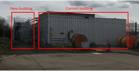
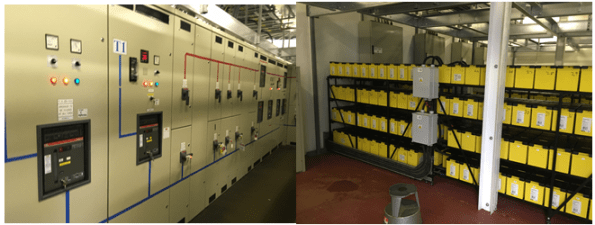
UPS
The new UPS system is being installed in a new building that has been built adjacent to the current East UPS system. Once the UPS system has been installed, each part will be individually tested before the system can be commissioned. A series of commissioning documents are currently being written by the construction team and will be reviewed by Atkins.
Below are some photos of the current battery rack and UPS control panels:-
That’s not a crack this is a crack!
![IMG_6764[1]](https://pewpetblog.com/wp-content/uploads/2017/03/img_67641.jpg?w=595)
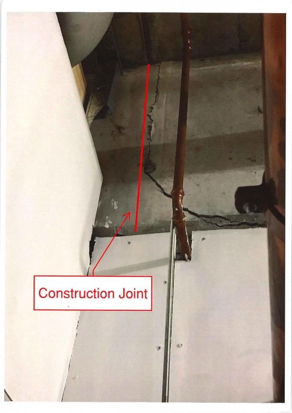
I thought BCT had problems! My boss and I were called in to investigate a crack at the Fortitude Valley Site. They are having some problems with their consultants. They have recently installed a crane and they thought it might have caused this cracking. It hadn’t what had caused the cracking was a construction joint that hadn’t been correctly designed. The connection had failed and there was evidence of shear cracks across the slab where the load had tried to redistribute. There are 20 floors of load on this slab!

Johnny Age 5 sketch
![IMG_6774[1].JPG](https://pewpetblog.com/wp-content/uploads/2017/03/img_67741.jpg?w=595)
This shear crack doesn’t look much but it shows that the transfer slab is in distress. Note the angle of the crack. Construction joint is above pipe
- Lack of specific construction joint for the transfer slab.
- The key of the construction joint was too close to the bottom of the slab. All of the vertical load was being transferred into the key detail at the bottom of the slab that then sheared off.
- In sufficient shear reinforcement.
- Construction joint located near an area of high shear.
- lack of oversight by structural engineers in Melbourne.
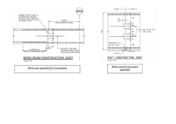
The Bad (what was detailed left) and good (detail from another site right). Note the key detail on the right and roughed finish

The offending construction joint before the pour. Note – no shear reinforcement and the key is close to the bottom of transfer slab!
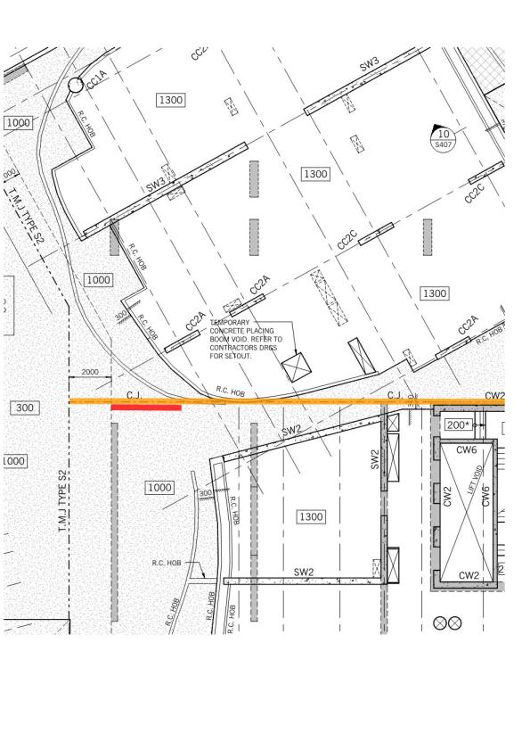
Plan view of the site (red is area of cracking). CC2A are columns that terminate at the transfer slab.
The Stage
I have started my Phase 2 attachment with Brookfield Multiplex (MPX) as what seems to be a site engineer and construction manager on The Stage project in Shoreditch, London and I want to provide an overview of the project and site to allow future blogs to relate to it.
Location
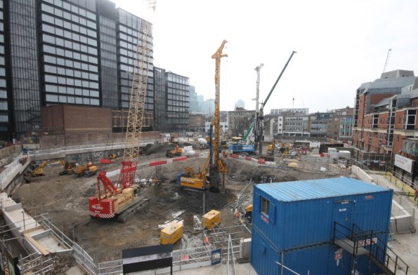
As can be seen from the picture below, the project is within drinking distance of “The City”. It also sits next to two other MPX sites, Principal Place Residential and Principal Place Commercial. There are also numerous other projects going on within the immediate vicinity making for a very congested area of London. It also means that some of the MPX staff (mainly H&S and QS related) are cross-decking between the projects, splitting their time between the sites.

General
The development is a mixed use scheme comprising of a 37 storey residential tower (building 1 – prestressed concrete), a 14 storey office block (building 3 – steel frame), and a 9 storey commercial and retail block (building 2 – prestressed concrete). In addition to the three largest buildings there will also be a performing arts pavilion, heritage centre, sunken amphitheatre, popup retail units (to hide a dated masonry substation) and the conversion of former Victorian rail viaducts; and all to be done to a BREEAM excellent standard. There is also the preservation of the remains of Shakespeare’s Curtain Theatre which date back to 1577. These remains are of international significance and are being preserved as the focal centrepiece to the development, hence the name.


Contract
The project is currently in week 19 of 20 of a Pre-Contract Service Agreement (PCSA) and conducting early works using a JCT D&B contract between the Client and MPX. I will be spending some time with the contracts team to better understand how this works commercially. The background to this is that Gilliard Homes (the Client) originally started the project themselves and stopped it when things weren’t going to plan, then they appointed MPX as Principal Contractor. They wanted work to happen quickly which is why a final contract for the project hasn’t yet been established. What this means is that there are legacy issues on site caused by the work conducted by Galliard Homes. For example there are some incomplete secant wall capping beams in place of which Keltbray, the main contractor on site, cannot guarantee the structural integrity of and will have to demolish. There are also existing utilities which the Client had previously moved from outside of the hoarding, which now lie in the way of the secant pile wall design. This requires the UK Power Network (UKPN) and BT to be involved to move the utilities before the secant wall is constructed. All elements resulting from the work conducted prior to MPX result in a risk being carried by the Client.
Current state of site
The site is currently in week 11 of 50 of early works, incorporating secant pile walls and bearing piles before excavating about 18m to allow for a bottom up construction. There are 2 x 90T piling rigs on site with respective cranes, working on 1m thick piling mats. The ground is being excavated from +15m AOD to +11m AOD before props are installed to allow further excavation. Another important aspect of the project is the presence of the Museum of London Archaeology (MOLA), who are conducting archaeological digs on site. We were taught that archaeological finds are likely to cause a significant delay to a project. However, it is a key part of the brand of the development and MOLA’s digs are being facilitated by MPX throughout the project and time has been put into the program to allow for archaeological overruns. The only finds being preserved are those of the Curtain Theatre which dates back to 1577. This has been fully excavated and has since been covered using polystyrene, steel plates and some very expensive aggregate. This means that the area under which they lie can be trafficked and used for stores. The presence and exploitation of the archaeological site and its future use as a major tourist destination means that the development does not need to incorporate any “affordable housing”. There are also other archaeological digs being conducted on site but these will all be recoded and removed by MOLA.
Piling methods
Currently there are bearing piles and secant pile walls using guide walls being constructed. However, I noticed that contiguous piles were mentioned in the H&S plan. This will be a subject of another blog. In the meantime the piles here are CFA using polymer (polymer plant in the picture is hidden by the blue ISOs). You can hear the suction from the London clay when the auger is removed from the casing. I will also see the first of the plunge piles being constructed in the next few weeks. I will do a separate blog about the history of the soil in this area of London as it has some good historical background.
Key constraints
Hackney Council have a number of restrictions to the site, the first of which is the working hours. The site is limited to weekdays 0800 – 1800hrs and Saturdays 0800 – 1300hrs. This means that the piling has to be at a practical stage every day to finish at that time. Any over-size loads are only allowed to be delivered overnight or at the weekend. There are no actual sound limitations imposed on the site so the project has a self-imposed noise limit of 78dB, which is the average noise level measured from the city. A full pre-construction survey was conducted of the surrounding buildings and their movement is being monitored. Of interest is the tilt monitors installed on the listed pub at the western edge of site. I note that the monitor recorded 6mm of deflection at 2030hrs last night (everyone had left site by then), correlating with the pub opening times. It has also been noted that it deflects by similar amounts when the beer is delivered to its cellars. Every time a monitor, whether sound or tilt, is triggered it is automatically logged on Information Exchange (software) and a report is to be filled in. That, in conjunction with the pre-construction survey, are used to establish whether the site causes any damage to surrounding buildings.
Another building which forms part of the site boundary is a 1950s masonry UKPN substation which has already been damaged by the back of a bucket when a subcontractor broke from an agreed method statement, an issue of non-conformity which has all been resolved. It is being closely monitored for movement as it apparently supplies electricity to half of the city.
Issues
Live substations. There are currently 2 live substations on the site which require temporary substations for the duration of the project. The installation of the temporary substations and the removal and decommissioning of the old has already involved a lot of interaction between subcontractors and utilities agencies. It has been interesting to see how the interagency interaction is managed by the MPX team and has been the basis of me learning how MPX operate on the site.
Site accommodation. The site accommodation was inherited by the work done by the Client previously and is deemed inadequate for MPX. Its size and location is critical to the project’s progress and the responsibility for its implementation have been given to me. In the short term it needs a temporary expansion in its current location to cope with an increase in the female workforce, to coincide with MOLA increasing their numbers in June. In the medium term a 4 storey 40m x 12.5m modular temporary accommodation block will be built on a concrete slab still to be constructed on the southern edge of site. This will house approximately 1200 personnel and will be complete by November. Following this the existing site accommodation will be refurbished and expanded to facilitate the latter stages of the project when the personnel reduce and move out of the 4 storey block. I have now been given the responsibility of this site accommodation project and have mid tender scope if works meetings with two suppliers to discuss the options next week.
Office politics. The main construction manager has resigned (on my day 3) after being on the project 9 weeks. This means he only has to give 1 week notice and will be leaving next Wednesday. It would appear I am now mid handover/takeover with him, hence the site accommodation project switching to me. I have already seen there is a case of office politics, largely based on personalities. It will be interesting to see how this progresses and how it differs from what we are used to. It may stem from the project office being dislocated from the site office by a few streets; naturally I think this causes a bit of friction between the two.
Summary
This blog covers an overview of the project and an experience of my first week here. It provides a starting block to help orientate future posts about the project and gives a rough idea of what will be involved here at The Stage. Meanwhile I will come up with various ways of getting Shakespeare into future blogs.
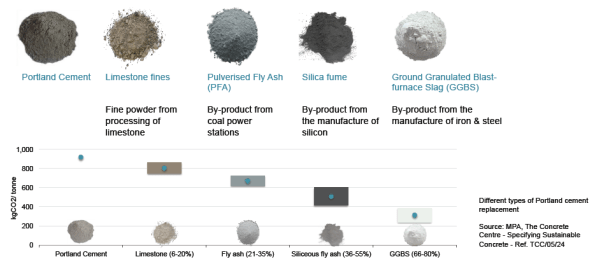
Reduce your Embodied Carbon!
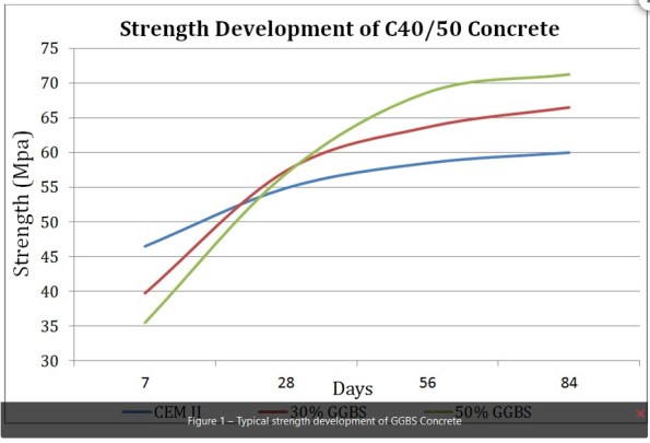
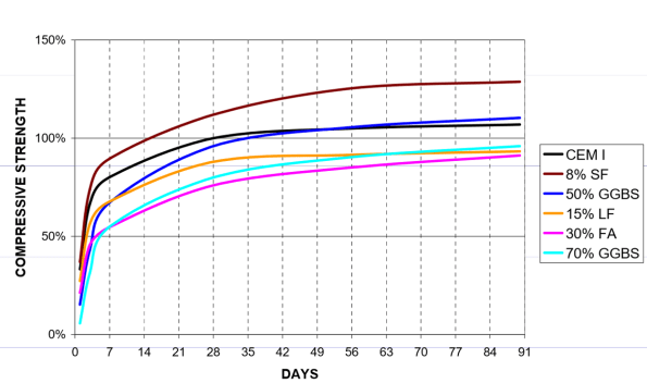
In my previous blog, I mentioned I would be involved in an Embodied Carbon (kgCO2e) study to be completed retrospectively on Gatwick’s newly finished Pier 1. Here are four generic recommendations for embodied carbon (and cost) reduction that could be applied to any construction project.
Useful to those currently in design offices writing design specifications and those going into phase 2 who might influence materials specs – some of these are a great way to save your client money, helping them to meet embodied carbon reduction targets, whilst providing perfect evidence of achieving UK SPEC competency E3 – ‘Engineering in a way contributing towards sustainable development’.
They may demand a broadening of the mind of clients / design colleagues to gain agreement!
- Replace up to 50% of cement content of concrete with Ground Granulated Blast furnace Slag (GGBS): (the civils will know more about strength implications and codes for this but BS 8500 gives the guidance on tolerances).
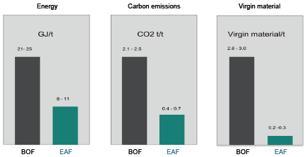
- Specify Electric Arc Furnace (EAF) steel (up to 100% recycled steel) over Blast Oxygen Furnace (BOF) steel (up to 30% recycled steel).
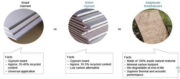
- Consider natural materials for internal building fabric. Caveat to this is that the ‘adaptavate Brethaboard’ below will require thicker plaster finish skim than the other two. Other alternatives products exist using natural clay which can absorb and release moisture into internal space, thereby passively regulating humidity.
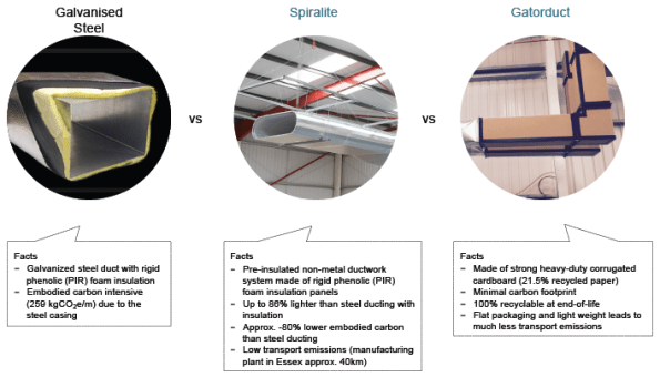
- Replace traditional steel ductwork with alternatives. To me, this might be the most difficult to get agreement from a client familiar with steel design going in and indeed steel ductwork is the generic requirement for all of Gatwick’s HVAC systems. However, in certain situations, such as relatively short lifespan / high turnover retail installations, the Gatorduct might be an better option.
I’d be interested if these types of products are commonplace on other sites indicating that perhaps Gatwick’s construction department remains too traditional / slow to catch up? Or maybe just meeting programme drives designers / contractors to stick to what they know?
Slides to go with Tom’s reply:
Defects in Melbourne Fitout
I am currently working in the “tenancy team” at Norman Disney and Young in Perth CBD. The tenancy team completes small scale building services consultancy fit out projects in a short period of time – usually a couple of weeks from start to finish.
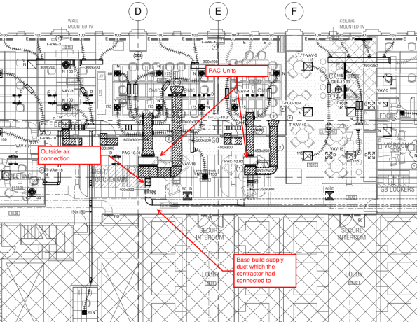
Amongst several other small projects, I have been given responsibility to consult on the mechanical construction phase of a HSBC tenancy in Collins Street, Melbourne. During the commissioning phase, a colleague of mine in Melbourne compiled a defect list, which happened to be extensive and include a number of concerning items. Given the tight timelines, by the time I received this document, users had moved in and started operating in a functional office space. One defect in particular was alarming – the mechanical contractor had connected outside air provision for two packaged air conditioning (PAC) units to the existing base-build supply ductwork. This presented a series of problems:
- Insufficient outside air provision to the two main meeting rooms.
- Imbalance of the existing base build system.
- Conditioned air being introduced to return air in the PAC mixing boxes.
To make matters worse, the client has unsurprisingly received complaints from the users – half complain about being too hot, while to rest are grumbling of being too cold. As the proverbial rolled down hill in my direction, I was asked as the mechanical design authority to rectify the situation. Both the builder and mechanical contractor were naturally eager to shift responsibility to the mechanical design, when in fact the system had been installed incorrectly. After an afternoon of rather animated phone calls and meetings, the mech contractor is now starring down the barrel at removing office users, taking ceilings down and installing the ductwork correctly. And rightly so! Understandably, both the builder and contractor were set on blaming the consultants design and I had the pleasure of going through the system design calculations with both parties. Luckily NDY’s design and quality assurance for this particular project was thorough and correct.
See Mark up attached.
I am somewhat surprised that the builder/ project management company allowed the user to move in before all of the defects had been addressed. Additionally, the original commissioning results are incorrect, invalid and wrong. To that end, I am pushing my project leader to request a re-test by the mech contractor – with a perhaps a young, enthusiastic, British engineer in attendance 😉
Update – Picture for you Fran.
xx

Mendeley Desktop…it’s free!
Whilst writing my thesis I have found Mendeley Desktop to be an excellent reference management system and the citation plug-in for Word is well worth downloading as well. I only wish I had listened to Mark Hill and downloaded it before starting TMR 1!
Check it out – https://www.mendeley.com/
