Archive
‘Expectations for those heading to Australia to work for Multiplex’
1. Multiplex have an excellent reputation in Australia for being a ‘fair’, reputable builder. They aim to employ good people, pay well but expect a lot!
2. It is highly likely that middle management will expect 12 hours + per day. Get stuck in, but set your stall out from the start. My priorities were academic work, gaining varied site practice and experiencing Australia – not working all hours to get my line manager promoted.
3. They push the contractors hard. Some bully, some build relationships, which was interesting to observe.
4. They work in fast paced environment. I found processes, general administration and management of pers to be lacking in comparison to what I’m used to. They were clearly focused on building stuff on time and making money $$$$ !
5. What we consider as unethical practice happens every day on site! (in WA anyway)
6. Attitudes towards health and safety can be extremely varied. Be mindful of the term “that’s a Saturday job”.
7. Workers unions are very strong and powerful in Australia. The majority of Multiplex projects are union sites which present their own management battles.
Give me a bell if you want to discuss anything further: +61 498 145 474
Playing the blame game
My old site BCT – just seems to be the baddie in a 1980s B movie – it just won’t die. Every week brings a new issue that needs rectification. Multiplex are expecting to make a $20 Million loss on the project.
I am spending a lot of time conducting what I call ‘Post Mortems’ on projects. Each one could be a TMR by itself and can be depressing/interesting depending on how morbid your curiosity is. There are a lot of firings going on and these Post Mortems are make or break for some people. My boss described it thus – we don’t fire them ourselves we just put the ammunition in the gun. Monday saw an interview without coffee for the main players in the BCT project team. Why is your project already $1.5 M over budget in reo and you have only just come out of the ground? Below is an email of my assessment of the reo overrun sent to my oss :
The facts of the situation are these:
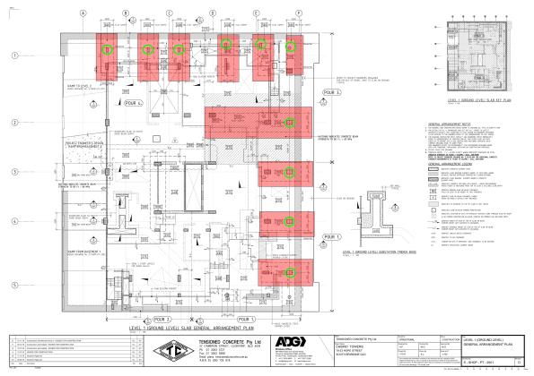
- Projected versus Actual. The greatest increase in reinforcement has occurred at Level One with approximately 6.5 times the reinforcement projected( 107 T against projected 16.2 T). The majority of this reinforcement is in the transfer beams on Level One (84 T). This leaves approximately 23 T of reinforcement in the remainder of the Level One slab (not including mezzanine).
- The transfer beams were added due to issues with the basement retention system. The original design called for pad footings close to the secant pile wall. However, because the secant pile wall was not deep enough in the North and East of the site, there was concern that the footings close to the wall would undermine the bottom of the wall. The decision was made early to remove the pad footings rather than issue the piling contractor with a variation. Subsequent consequence analysis seems to have been focussed on the geometrics and car park spaces. There appears to have been no formal consideration of the cost impact of the additional transfer beams. As a rule of thumb, one transfer beam costs approximately $35,000. The decision to remove the columns in the basement and use transfer beams resulted in an extra 10 transfer beams (approximately $350,000).
- Contract Award. There are no transfer beams included on the Level One sketch in the Post Tension tender documentation. While the transfer beams are shown in the capping beam documentation in S-CD-09-001 Retention Wall and Capping beam Plan, this information was not transferred to the Level One drawings. There appears to have been no tracking of the transfer beams on a design register and it does not appear to have been communicated to the sub-contractor effectively during the tender process.
Assessment. The existence of the capping beam drawings muddies the water somewhat. On one hand the sub-contractor should have been aware of the need for transfer beams from the capping beam drawings but, could argue that it was not covered by his scope because it was not on the drawings of Level One. There were several failure of process within the Multiplex team.
- Failure to communicate the addition of the transfer beams with up to date drawings prior to contract award.
- Failure to understand the second order consequences of removing the columns in the basement (Cost).
Regards,
Doug
Having thought that the PT designers had got the message about putting too much conventional reinforcement in the slabs, I received the new drawings for Podium Level 2. The previous iteration had approximately 60 T ($120,000 over budget for level 4) of reinforcement over what had been agreed in the contract. Having worked late into the night to get an answer to the project team on the savings and ground truth of their design I was disappointed to discover this iteration had shaved a meagre 15 T off that figure ($30,000 saving). Not good enough Mr Consultant show again!
In other news I have been playing around with STRAND (finite element analysis software) trying to assess the natural frequency of a 20 m span conventional reinforced concrete beam. The beam is supporting a swimming pool above the ballroom at the Jewel Hotel on the Gold Coast and there is concern that the chandeliers could swing around because of the vibrations from the pool. It’s not urgent but its fun to play with when BCT gets depressing.
USACE Funding Model
Introduction
Well, it’s been a little while but I though now was as good a time as any to jump back into the blog-o-sphere. Like everyone else I’m in a design office, the work isn’t too bad despite having to do all my calculations in strange units of measurement such as inch-kips and force-lbs; which means that I don’t really have any idea what answers I’m expecting to get. No change there then!
I’m still working for USACE, but the commercial environment is like something halfway between a commercial company and a non-profit government organization [sic]. I’ll do my best to outline some of the budgeting and funding principles below:
The Military Design Branch (where I’m now based) is an arm of USACE that essentially carries out design work on behalf of the Baltimore District. Despite being a Corps of the US Army, USACE are not entirely publicly funded, and are required to cover their own overheads (including wages) by charging a fee for their services on any projects undertaken. Legislation prevents the military from making a profit; however this arrangement means that the organisation is run somewhat like a business, with Districts required to break-even within a 1% margin. Performance (profit) is reported up the chain, with Divisional Commanders having the authority to support under-performing areas. Commanders are therefore required to effectively manage income and expenditure whilst aiming to hit the 1% profit target, after which any profit achieved (over 1%) are returned to the US Treasury.
MILCON Program.
The MILCON program is funded directly by the Senate, with budgets set on an annual basis according to performance, budget, program progress and projected work. All USACE costs associated with the planning, management and design of projects is taken directly from this source. There is therefore only a finite amount of work that districts can pursue, and it is usually delegated to divisional chiefs to determine which work/projects they wish to undertake according to the resources available to them. However, the final decision remains with the District Commander. Any remaining MILCON program work will then be sub-contracted out to commercial Consulting Engineers (I did an outline design for a one-storey VCP before being told it had been put out to tender!). The direct result of this arrangement is that clients operating within the MILCON framework have no direct say in who conducts the planning, design and management of their own projects, which is often determined by the capacity of the local USACE district office.
Construction Funding
The Senate annually funds the MILCON program, however these finances exclude the costs associated with new construction projects or renovations, instead clients apply directly to the Senate for these projects. A formal bid process is initiated approximately two years prior to the anticipated project start date, whereby project scope and justifications are submitted and the bid is accessed against pre-determined government metrics. If approved, funds are released directly to the client, and used to cover construction costs (e.g. the JOC project). As previously, this means that the client generally has a choice as to which organisation will ultimately administer their own construction contract, however USACE are generally ‘chosen’ because of their reputation and specialist knowledge. In order for USACE to then meet the overhead and wage liabilities of the project delivery team a ‘supervision and administration’ fee is then charged back to the client. These fees are generally charged at a standard rate of 5.7%. As a hedge against poor performance by the contractor or unforeseen events/variations USACE will also typically also apply a 5% contingency value to the overall construction cost, as per the diagram below.

Contract Relationships
A fixed price contract model is employed on all Government projects, and the client is legally obliged to compensate USACE for all work conducted. However, at the outset of any project a one-off contract is negotiated which includes rates and fees for all design costs, management, profit and overheads. Contract ‘variations’ however are always subject to inter-party negotiation, which due to their uniqueness and un-foreseeability are not agreed prior to the commencement of work. Disputes or claims that arise from variations can and are still subject to legal proceedings and/or arbitration. However, the Government’s policy of ‘fair and reasonable’ treatment generally ensures that most of the Principal Contractor’s disputes are settled prior to reaching court. This policy can benefit both parties, however first-hand experience has demonstrated a willingness for the Government to concede positions to the Principal Contractor that they could reasonably have argued and won. My observations were that the Contractor usually came off better because they threw the toys the furthest!
Innovation in construction materials
3-2-8-cc-defence-1604 cc-other-sandbag-reinforcement-1604
I attended a presentation before Christmas from a company called concrete canvas.
“Concrete Canvas Ltd. manufacture a ground breaking material technology called Concrete Canvas that allows concrete to be used in a completely new way. Concrete Canvas was originally developed for the award winning Concrete Canvas Shelters, a building in a bag that requires only water and air for construction.
Concrete Canvas is a flexible concrete impregnated fabric that hardens on hydration to form a thin, durable water proof and fire-resistant concrete layer. Essentially, it’s concrete on a roll.
Concrete Canvas Shelters are rapidly deployable hardened shelters that require only water and air for construction. A CCS25 variant can be deployed by 2 people without any training in under an hour and is ready to use in only 24 hours. Essentially, CCS are inflatable concrete buildings.” (http://concretecanvas.com/).
I think they also featured on Dragons Den but didn’t get funding. I think it’s a great product. The shelters could perhaps be beneficial in longer term displaced persons camps owing to the fire resistance, although the market has been a lot less interested in these potentially (I assume) down to the increased cost, logistics and complexity compared to canvas/plastic alternatives.
On the other hand, the canvas rolls have sold very well worldwide, as it is a much cheaper alternative to reinforced concrete for non-structural applications, and is cost effective even when the cost of shipping to Australia is included (although this reduces the environmental credentials). Costain have used a lot of this stuff for lining ditches, stormwater channels and ponds, and bunds. The EA have used it for flood defences, and they also report the military have used it in Afghanistan (I think for improving Hesco and ditches).
The company has secured compliance certificates for fire resistance, age testing, abrasion resistance, chemical resistance, and impact resistance (for pipeline coatings). The use of the product in non-structural applications supports product development by allowing them to secure the accreditation above, provides funding and increases market awareness. But their ultimate aim is to push the product as a structural application. Due to the increased risk this poses, there are many more barriers, and more checks and balances required. It’s easy to get something into the non-structural market, essentially just prove that it won’t kill fish and newts. Proving that something won’t fail and kill lots of people is much harder. The future is also uncertain for manufacturers – will Brexit change the nature of BS EN accreditation, raising the bar or making investment in securing accreditation now irrelevant in the future? The Institutions say not – but who knows for sure?
Blog 3 – the third and potentially final blog in the Tony Strachan innovation series will look at the Stavros Niarchos Foundation Cultural Centre and how innovation was achieved by Expedition (and others). This featured in the January 17 issue of The Structural Engineer in case anyone wants a spoiler of the article I will be shamelessly presenting.
Update: I checked the info that concrete canvas sent through ref the previous military uses for their product. The case studies are linked at the top (as it’s the only place wordpress will let me put it) for info – but don’t let them stifle your creativity! I’m not aware if they’re working on military projects currently.
Technological innovation in construction
I’ve been involved on the periphery of a few discussions with innovation in construction recently so I thought i’d type out my musings in case I want to use it in the future. Plus i’ve just ordered on Deliveroo so i’ve got some spare time tonight. Unlike the beautiful “E&M cut and pastes” from a TMR it’s not neatly formatted, more like the words have just fallen out of my head (akin to JMs feedback).
Firstly I attended a talk at the ICE on technology as a management tool, delivered by Highways England (should be available as a recorded lecture soon at http://www.ice.org.uk/recordedlectures , along with other videos for filling a boring winter commute). They’ve seen tangible improvements in management or delivery from technology in the following areas:
- Remotely Operated Temporary Traffic Management System (ROTTMS)
- Stationary vehicle detection software to prevent, detect and monitor incidents.
- Integration of design, operational, construction and environmental risks onto BIM 3D modelling.
- BIM 3D and “4D (cab view)” safety briefing and supply chain planning.
- Real-time view of national traffic conditions via the National Traffic Info System (NTIS).
- A digital component library – “design once, use repeatedly” (although you need to be careful that the use of standardised designs doesn’t stifle innovation).
- Drone surveys – reduction in risk to manpower on highways
- Data acquisition and analytics during construction to develop a “Haynes manual for construction”.
- Live task monitoring and reporting of progress, resource levels, reserves etc.
However, despite the successes above they admitted that introducing innovative technology is not straightforward. I’ve read that BIM will mean we don’t need to rely on physical surveys anymore. Great news, but as they said in the presentation, surely we shouldn’t have had to do that since CAD was first used if it was properly employed. Therein lies the problem, before introducing a new technology you first need to make sure the people and processes are ready for it. Definitely a lesson in there for the military (MAKEFAST?, MOSS?, JPA?, ORIENT?)
Look at the people (why are they not already doing it and are they ready for it?) look at the business model and processes (what is the need and what are the limitations?)
Barriers to adoption of technology can include confusion (certainly in my case), training burden, hardware and software costs, data storage costs, security of data, reliance on specialist personnel for operational continuity and what if it all goes wrong?
I attended a workshop on innovation as a test for some training the Think Up are delivering (https://thinkup.org/) and this presented a similar idea to that which I think was first coined in a systems perspective of creativity by some author with a crazy name full of consonants (http://www.sagepub.com/sites/default/files/upm-binaries/11443_01_Henry_Ch01.pdf).
He presents it diagrammatically as:
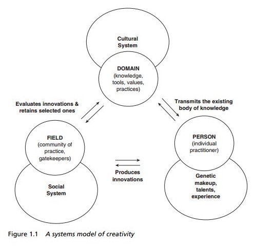
I prefer my own notes from the workshop:

The workshop concluded with a discussion on how Expedition can encourage innovation internally. There were many suggestions including having a “dunce in residence” to ask seemingly stupid questions that then spark innovation (a role I am happy to fulfill), more talks from suppliers, innovation reviews at key design stages. They were enthralled by my suggestion of “tea & toast” as a useful discussion forum when I said the military do it. They thought it showed the military as a creative and forward leaning organisation allowing daily sessions for open discussion of ideas without an agenda. I did point out that it was just an opportunity to eat toast and occasionally drink port but I think it may make an appearance in the office soon.
As a look forward – the next installment will feature how we can use innovative materials. There may or may not be a quiz afterwards with Champagne (Asti) up for grabs.
Analysis Software
There’s been quite a bit of discussion recently regarding what analysis software is being used in various design offices. There are a wide range of options and the practice I am with have developed some loose guidance on which structural analysis software should be used for different design problems as outlined in the figure below.
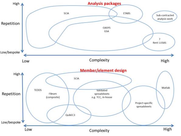
So far I have used SCIA, TEDDS and bespoke excel spreadsheets. It has been a steep learning curve to get to understand some of this software, during which time I’ve been very grateful for YouTube. There are some really great examples to follow. Expedition have also published a useful table on their internal website listing which members of staff you should speak to for advice on different packages – this has proven extremely useful.
I was initially frustrated that we use STAAD at PEW as it now seems very simplistic and doesn’t cover the complexity or design options of some of the other software. However, I think it is useful to demonstrate the process of modelling and analysis, and I suppose no matter which software you choose you can’t cover all the options. I think it may be worth looking at TEDDS if a replacement is ever sought. TEDDS for Word is very powerful and would prove useful during design exercises.
One thing that has really surprised me is the use of simpler software to check software output rather than hand calcs. It seems that there is so much familiarity and confidence in simple software like TEDDS that people are confident they won’t make the input errors. However, I don’t have that intuitive understanding of TEDDS yet so I don’t feel comfortable doing that. CIRIA technical note 133 is a useful guide to checking computer analysis.
My level of confidence with the software remains low, but this is improving as I build up an understanding of the design options that can be applied and how these change the model.
Remember these John?
As many of you will know I have opted to stay with the BP Exploration Operating Company Ltd (BP) for Phase 3. I am remaining with the Projects and Modifications (P&M) team and so will continue in a mainly Project Management role. In order to gain design competency I will be taking on work from the Discipline Engineering (DE) team. One of said pieces of work involves this:

GEC CTU15 Relay
No, not a flux capacitor. This is an obsolete mechanical protective relay from the aging Magnus platform; E&Ms will remember studying these in great detail with John Marsh. The problem is that being obsolete there are no spares available if any fail, which some have started to show signs of doing during routine testing.

BP Magnus
The task for DE is to find a solution which doesn’t involve replacing/modifying 35 year old feeders, air circuit breakers, bus bars and current transformers or 39 electrical cabinets. The Magnus’ high voltage transformers and feeder setup are a bit of a unique design and even replacing the existing current transformers would be at best challenging and at worst dangerous. Unless you shut down the entire platform, which at $1million per day production loss isn’t going to happen.
My job is to engage with a vendor who claims to be able to utilise the existing relays to develop a plug and play digital replacement. This may be using the existing casing or an interface plate to install a contemporary relay in the existing Magnus cabinets. If the solution is viable and passes a FAT, I will need come up with a plan of prioritising the replacement of relays on the platform, the testing procedures and the programme for installation. There will inevitably be quite a number of discrimination curves to draw too. Best I jump on Air BP to Manchester and undertake some vendor engagement…
Concept Design…
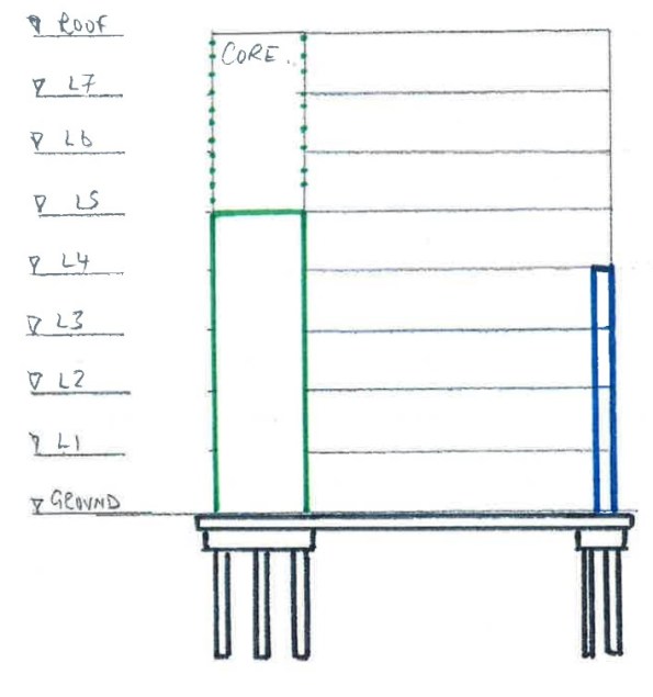
A potential client, wanting a 7 storey building, is keen to discuss the advantages of ‘beneficial occupancy’. Interestingly the most valuable floors are levels 4 to 7 and as such, these are the priority. Having been approached with this request, RBG have offered a concept design which allows the contractor to programme the more valuable, upper levels ahead of the lower.
Step 1: Foundations and raft slab (black)…

Step 2: Jump the core (green)…
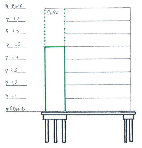
Step 3: Once the core has reached the required height (level 5), secure 15m prefabricated column (blue)…
Step 4: Connect column to core at level 4 with prefabricated steel truss (red)…
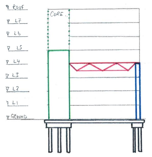
Step 5: Infill level 4 with precast slab and then progress concurrently through levels 5 to 7 and ground to level 3 using conventional falsework.
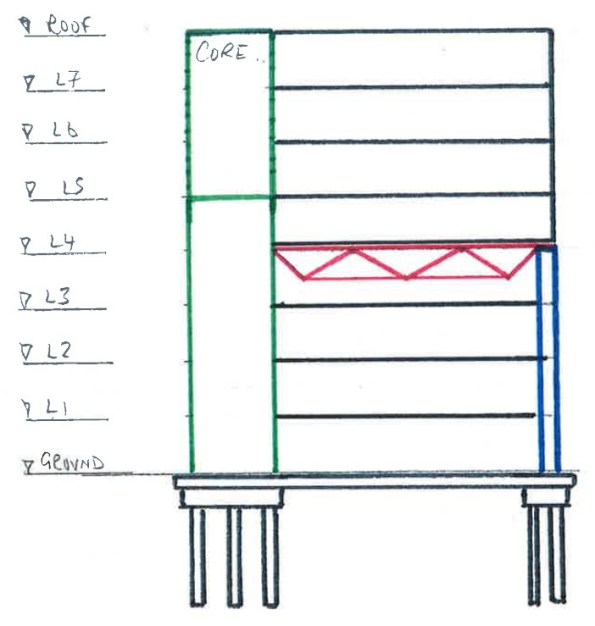
Step 6: Remove truss.
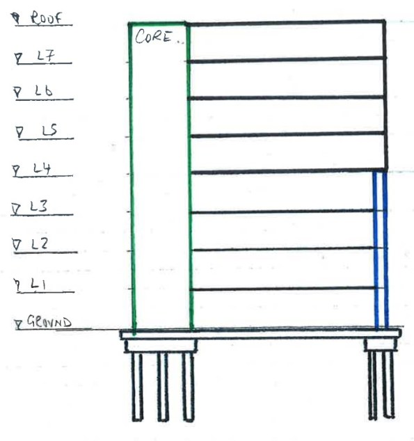
Whilst simple, this approach delivers the most valuable areas of the asset to the client earlier than conventional methods. It also negates the need for a ‘deep beam’ arrangement at level 4, maintaining level 3 headroom.
Unfortunately due to commercial sensitivities, I haven’t been allowed access to the cost benefit analysis of this approach. I have however been informed that whilst this approach costs more in materials, it delivers the most valuable areas of the asset sooner. The earlier delivery of levels 4 to 7 translates to an earlier profit for the client. This advance of profit offsets the inflated cost of materials.
Water, water everywhere…things that I have learnt about hydraulics
Summary of Secondment to Warren Smith and Partners
Introduction
Following last week’s update on all things mechanical, this week covers my secondment to Warren Smith and Partners, the project’s consultants for Hydraulics, Dry and Wet fire system. In addition they also have departments for civil and stormwater drainage design. I benefited from this design secondment in 3 areas:
- Extending technical knowledge of services engineering.
- Reinforcement of theory and knowledge from PET course.
- Practical aspects and implications of theory.
Aim of secondment.
The aim of the secondment to WS&P was to develop a thorough understanding of the processes used for the design of hydraulics, dry and wet fire services and civil and storm water drainage.
Timetable.
- Monday 17 Oct 16 – Civil: Storm water and drains. Inc site visit to domestic development.
- Tuesday 18 Oct 16 – Civil: Storm water and drains. Inc. site visit to Barangaroo development.
- Monday 24 Oct 16 – Hydrant and potable water. Fire (Dry/Wet).
Key documents.
- AS 1670: Fire detection, warning, control and intercom systems – System design, installation and commissioning.
- AS 1851: Routine service of fire protection systems and equipment
- AS 2419.1: Fire hydrant installations.
- AS/NZS 3500: Plumbing and drainage
- Part 1: Water services
- Part 2: Sanitary plumbing and drainage.
- Part 3: Stormwater drainage
- Part 4: Heated water services
- Australian Building Codes Board: National Construction Code 2014 Volume 3.
Overview of secondment.
Storm Water Design. WS&P uses two main programmes for design; DRAINS to model the catchment area and storm water runoff design; and MUSIC (Model for Urban Stormwater Improvement Conceptualisation) for stormwater treatment.
The outputs of DRAINS are used for the modelling within MUSIC. I undertook a short design exercise using MUSIC based on the Barangaroo Reserve Development in Sydney – the area circled in the figure below was an old industrial dockland and was converted to a public space and nature reserve (the hill is entirely man made). The requirement was for a reduction of >80% for total suspended solids, >65% nitrogen and >45% phosphate. Using a combination of onsite detention tanks, swales, filters and bio-retention I achieved this. Following the site visit to the Barangaroo Reserve development I believe I would have been able to further refine my design to remove some of the filters, thereby reducing the council’s ongoing maintenance burden for the stormwater system.
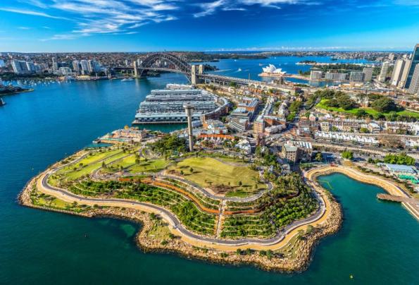
Figure 1: Barangaroo reserve development can be seen in the foreground.
The New South Wales government states that the minimum requirement for post-development flow be no greater than the pre-development flow. However, each local authority can set more onerous requirements. For example, Hornsby Council in Northern Sydney states that the 20 year post-development flow must be less than the 5 year pre-development flow. Understanding the local restrictions is therefore vital.
The site visit was to a small scale residential development where a plot was to be split in two and both plots developed. The purpose of the visit was to ensure that all parties were aware of the implications of the requirement to meet Hornsby council’s post-development flow standard, to ensure that there was sufficient mains pressure and to comply with the water authorities’ requirement for both plots’ waste water infrastructure to be entirely separate. This latter requirement caused issues for the routing of the drainage from the second plot to the sewer system that would require the removal of community trees – this brought in another set of regulations about tree removal. As highlighted in the paragraph about, a thorough understanding of the local restrictions is vital.
Hydrants, hose reels, sprinklers and drenchers. All the requirements for fire equipment are based on the size, construction and use of buildings as well as the available mains water pressure and volume flow rate. The requirements are laid out in the National Construction Code of Australia, the structure of which also acts as a flow chart to assist in the development of the building design.
- Part A: Classification of building.
- Part B: Structural provisions.
- Part C: Fire resistance (classification, number of levels and volume of building)
- Part D: Access and egress.
- Part E: Services and Equipment. During the discussion about sprinklers it was clear that WS&P’s position was that as sprinklers control 90% of fires, they would, where possible, use sprinklers in their designs even if not stated in the code. This position is supported by the fire brigade and their inspection authority that have closed loop holes that allowed for the exclusion of sprinklers under certain circumstances.
In addition to the codes and requirements for fire equipment, the important installation features were discussed:
- Sprinkler heads are to be unobstructed in order to allow the sprinkler envelope to form.
- Flexible sprinkler pipes have a given bend radius. During installation it is usual for other trades to move the flexible hoses and possibly cause damage. This must be checked.
- Within ceiling voids, sprinklers also act as fire detectors, therefore removing the requirement for a separate ceiling void detection system.
The first two of these points have been useful during my quality assurance inspections.
Potable Water. WS&P uses PIPES for modelling all hydraulic designs – potable water, fire and hydrants. As potable water is an open system, unlike a heating system where the water can be treated, the constant flow of water degrades the pipes – oxidation and erosion – therefore the recommended circulation flow drops to <0.6m/s. Delivery flow can be greater and in line with the CIBSE values.
During schematic design the water authority provides details of the flow and pressure within the mains, the final design should consider the following factors:
- Minimum amplification of existing infrastructure.
- Minimum disruption to routine function of mains: from both connection to mains and location of connection.
- Reduction of mains connections as each one occurs routine service costs to the end user.
- Pumps requirements: If mains pressure is under 250kPa then a pump is required.
- Pressure reduction requirements. The max pressure at an outlet is 500kPa therefore pressure reduction may be required. Where there is a large step down, this should be done incrementally with reductions of between 25 and 50%. Best practice for preventing oversizing of RPZs is to install 2 in parallel (each designed for 50% flow) with a small bore (15mm) bypass.
Smoke Control Systems. As detailed from the Fredon secondment, the mechanical consultant produces the Fire Fan Control Matrix. This stipulates which fan has to do what in the event of a fire – the Fire Fan Control Panel and the Mechanical Control Centre are then programmed to enact this. It is important that all stages of the fire design involve both the Mechanical and Fire designers, and as stated earlier it is important to have a clear delineation of roles and responsibilities.
The Emergency Warning Intercom System (EWIS) for a hospital must be set up to minimise distress to patients. Therefore at the St George Hospital there are no speakers in the patient rooms, but to ensure that there is sufficient warning in each ward an additional mimic panel has been added at each Nurse’s Station. Therefore in the event of an evacuation the nurses are aware but immobile patients are not subject to the distress caused by listening to the automated evacuation warning instructions.
AS1670 covers fire rating copper cables, but not optical fibre. This gap is currently being resolved.
Key lessons learnt.
Standards must be fully understood, but also there is a requirement to be cognisant of the other national, regional and local regulations. The consultant’s value is clear in their expert understanding of all the levels of codes etc.
Design conditions for all circumstances must be understood – for example the difference between the potable water circulation flow rates and the acceptable distribution flow rates.
Designs should be optimised to reduce the end user’s maintenance requirements.
Recommendations.
With the wide range of expertise within WS&P, it could be an option for future Phase 3 attachments.
Free Champagne
So here’s the deal, the blogs recently have been pretty boring and long (thanks E&Ms). I’ve been to a couple of presentations on BIM recently and that’s also a long boring subject. I’m not likely to have to buy Champagne in the mess for any celebratory reasons in the foreseeable future so i’ll buy a bottle when we get back to Chatham for the first current STUDENT to translate all the TLA buzzwords below. Staff or former students feel free to play along separately for your own for personal pride/shame. I’m guessing this is going to be won by an E&M as this is their level of boring.
In the event of any disputes my scribbled notes are final.
PAS, CDE, PQQ, BEP, LOI, IM, CIC, EIR, LOD, MPDT, PIP, BIM.
