Sundrop Farms Project Update
This blog aims to provide an update on site progress, as well as demonstrating the wide range of tasks that seem to land on your lap as an engineer. Apologies if it is a bit long, not had a lot of time recently to blog.
My main area of responsibility (the pipeline) is nearing completion, with the filling for the hydrostatic testing taking place as I type, should take around 3.8 days. My involvement in this has been limited to developing the test procedure alongside the subcontractor and client, as well as ensuring the relevant standards are followed and John Holland isolation procedures are adhered to. It did however give me the opportunity to wheel out some P=ƿgh action when the client asked why we were not going up to the full test pressure (answer – because the pressure gauges are not at the lowest point). Other areas I have recently taken on include the intake and outflow at both the sea and project end, as well as the lining of the lagoon structures and all the associated pipework.
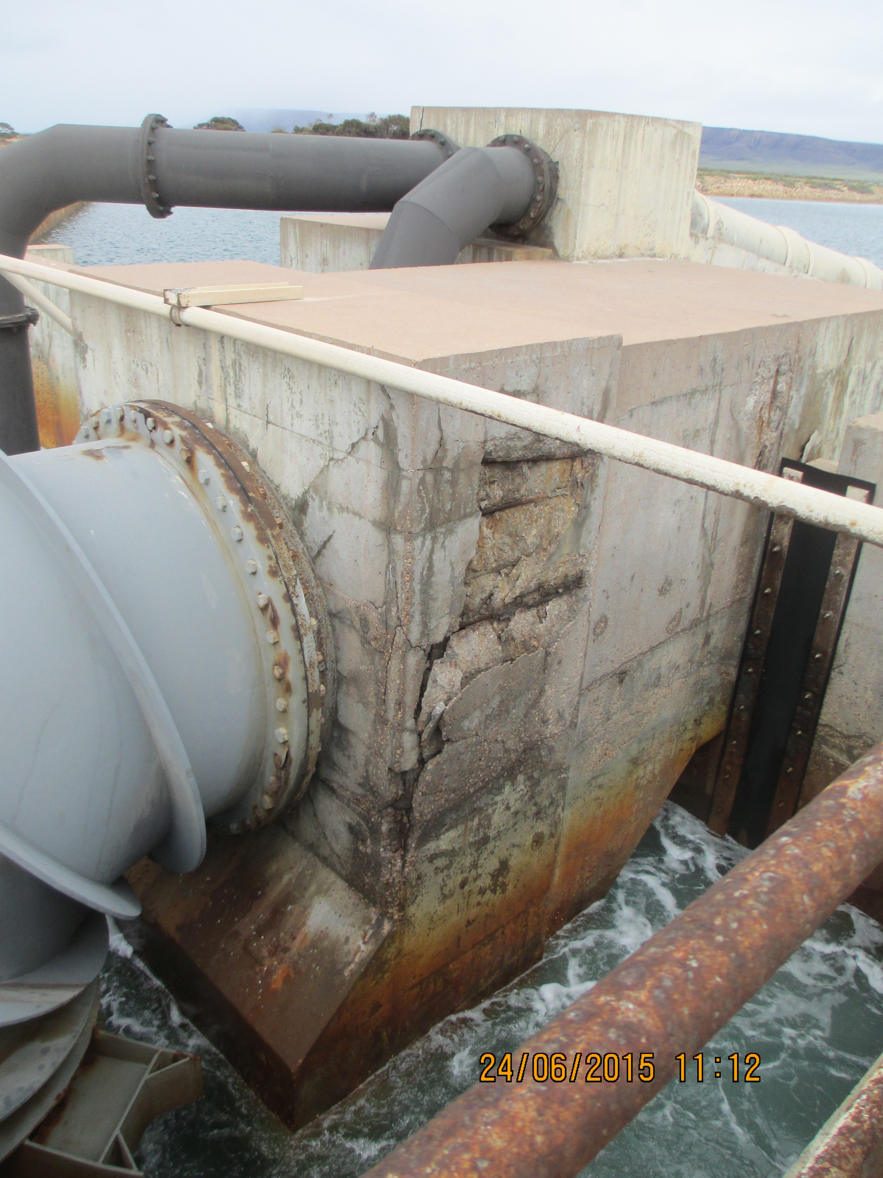
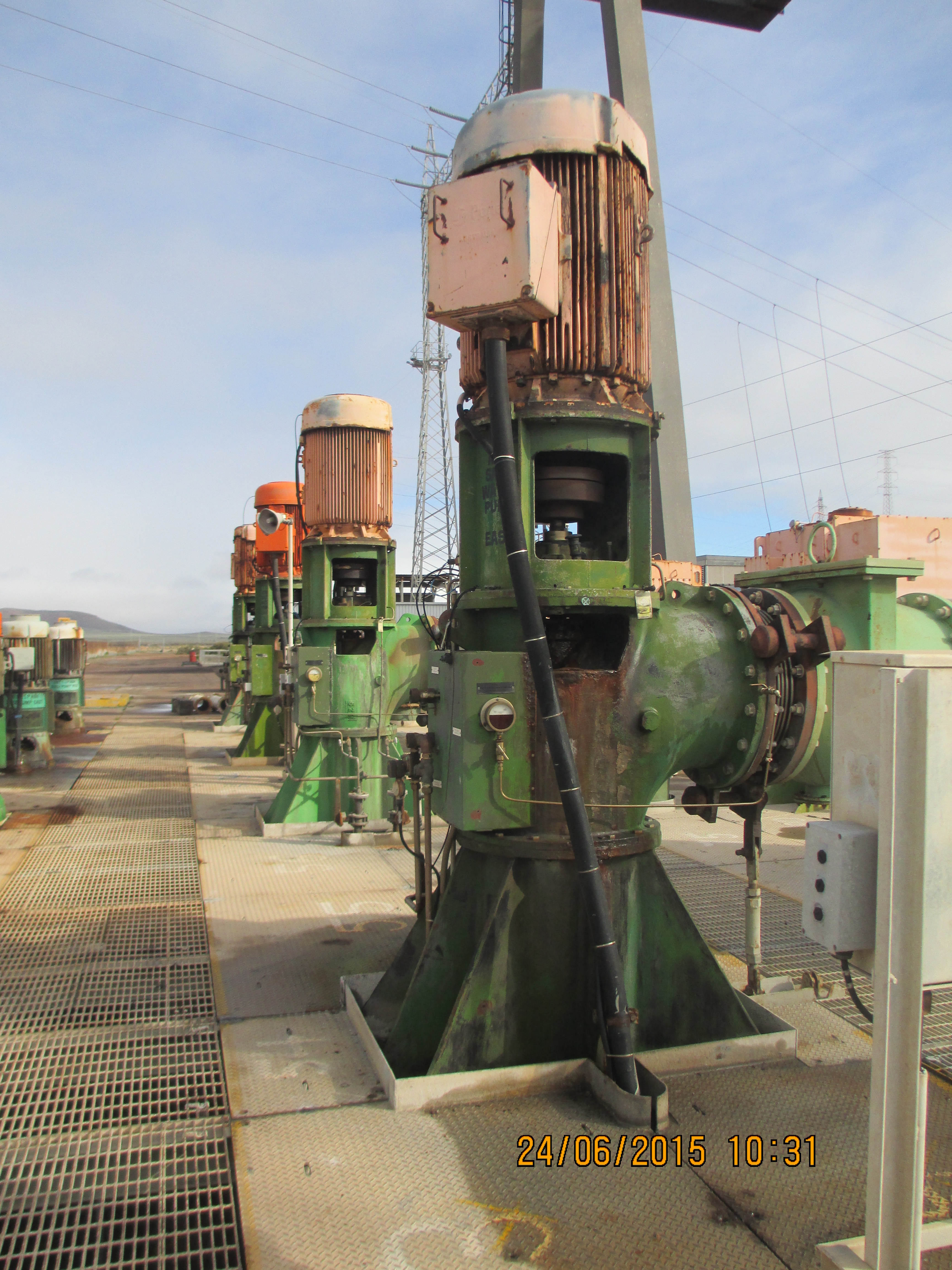
The intake and outflow for the pipeline at the sea end is a $1m package of work which has recently been awarded to Guidera O’Connor. I have been responsible for developing the scope of works, getting the designs to IFC stage, introducing the subcontractor to the project and on boarding their construction team. The design currently ties in with existing infrastructure at Alinta power station. A few weeks ago the power station announced its closure in 2016; previously this was due to be in 2030. This clearly has some major impacts on our project:
- Firstly the site is to be returned to the condition it was prior to the power station, including the inlet channel that we are building on and the control rooms that we were going to use for power. Currently this has been passed back to the Client to come up with a solution through negotiations with the land owner.
- Secondly the Environmental Protection Authority sign off for the brine discharge from our site was based on the outflow of the power station for diluting and mixing, prior to the water entering the sea. Further models are now in development by the University of New South Wales to analyse the impact.
A potential positive is the fact that the government is under pressure to do something about the number of unemployed persons in the area and as a result there are already discussions for a second Sundrop Farm project in the area, clearly this will be dependent on the commercial success of this one. At the moment we have been to soldier on with the current designs, with the hope that the Client comes through in the end otherwise we will have some major variations coming our way. I have included some photos of the existing infra structure firstly to show the state of disrepair that we are expected to link into and secondly to balance the fact that the remainder of this blog is civil based.

The contract for the lining of the ponds was awarded to Fabtech and was valued at $750,000 – at first I thought this would be a relatively pain free scope of work. After interrogating the drawings I discovered a whole can of worms in the form of buried services. Basically I have spent the last two weeks trying to find out who is responsible for what services, taking items out of various scopes of works and awarding variations to Fabtech in order to progress works as they are already onsite and we can’t afford any delays. In the process I have found gaps in both the design and procurement packages, which always makes you popular on site. One of the most surprising gaps at the moment is that there is still no plan for the waste water across the whole site, even though the subcontractor for buried services starts next week.
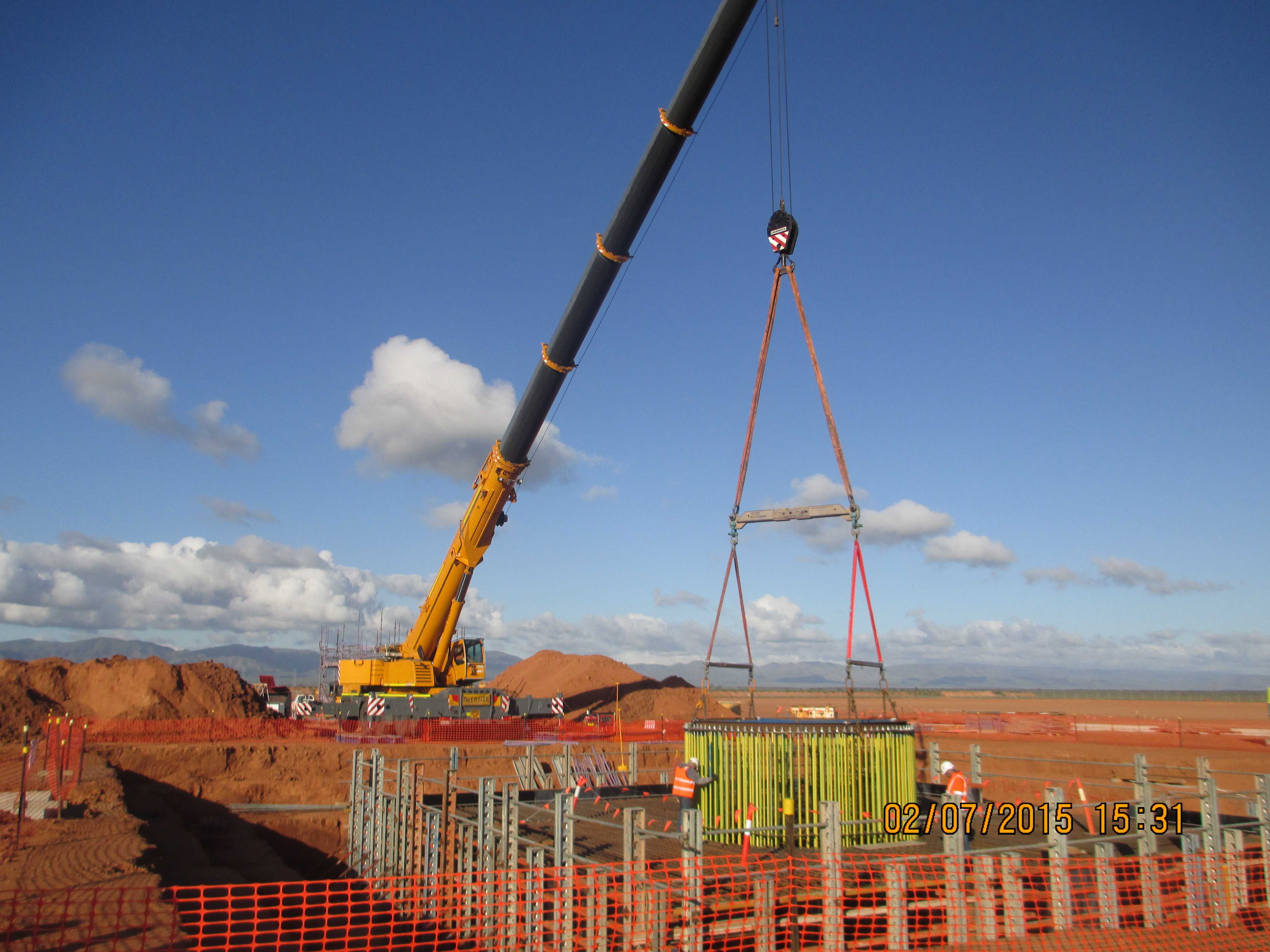
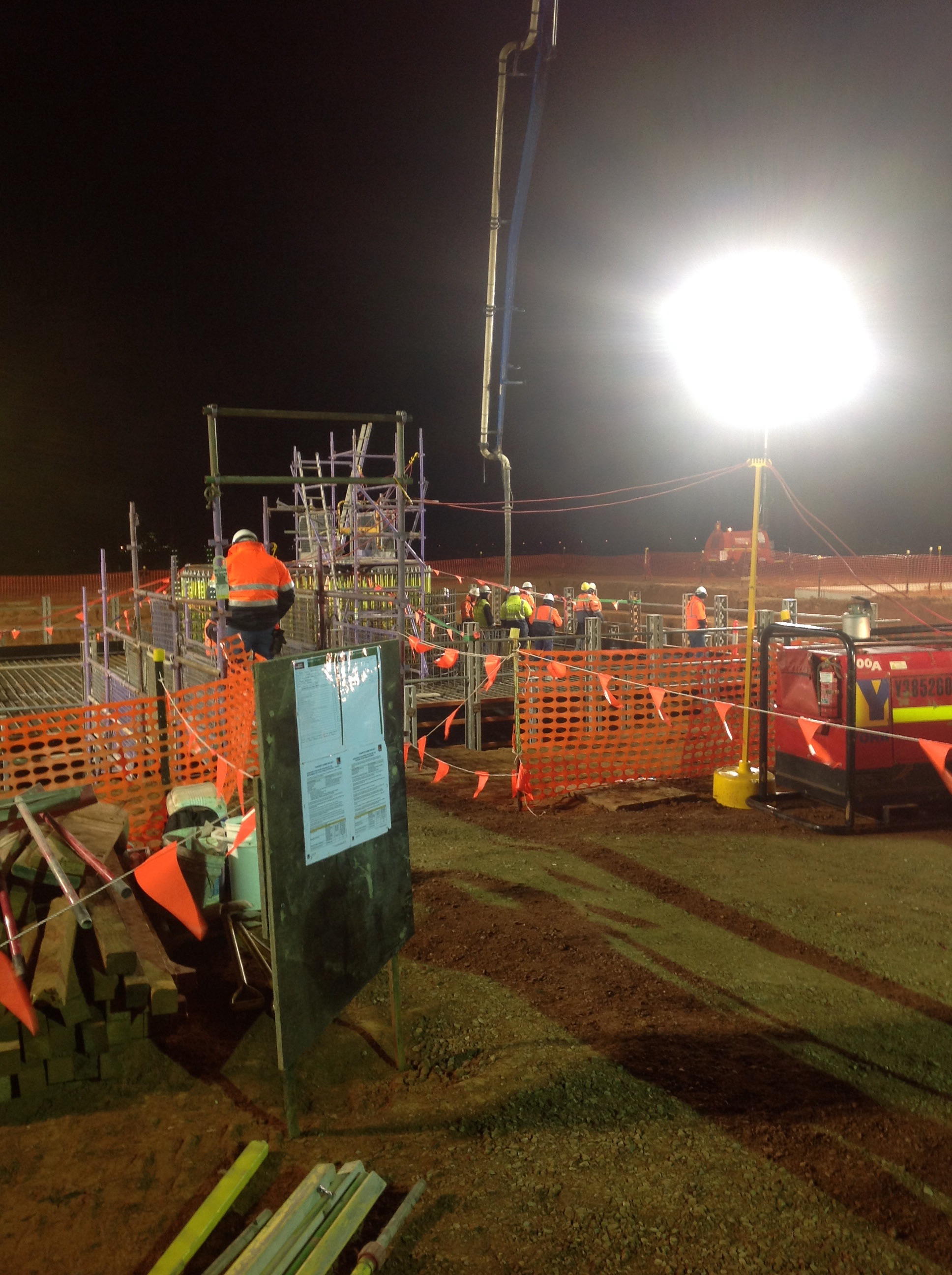
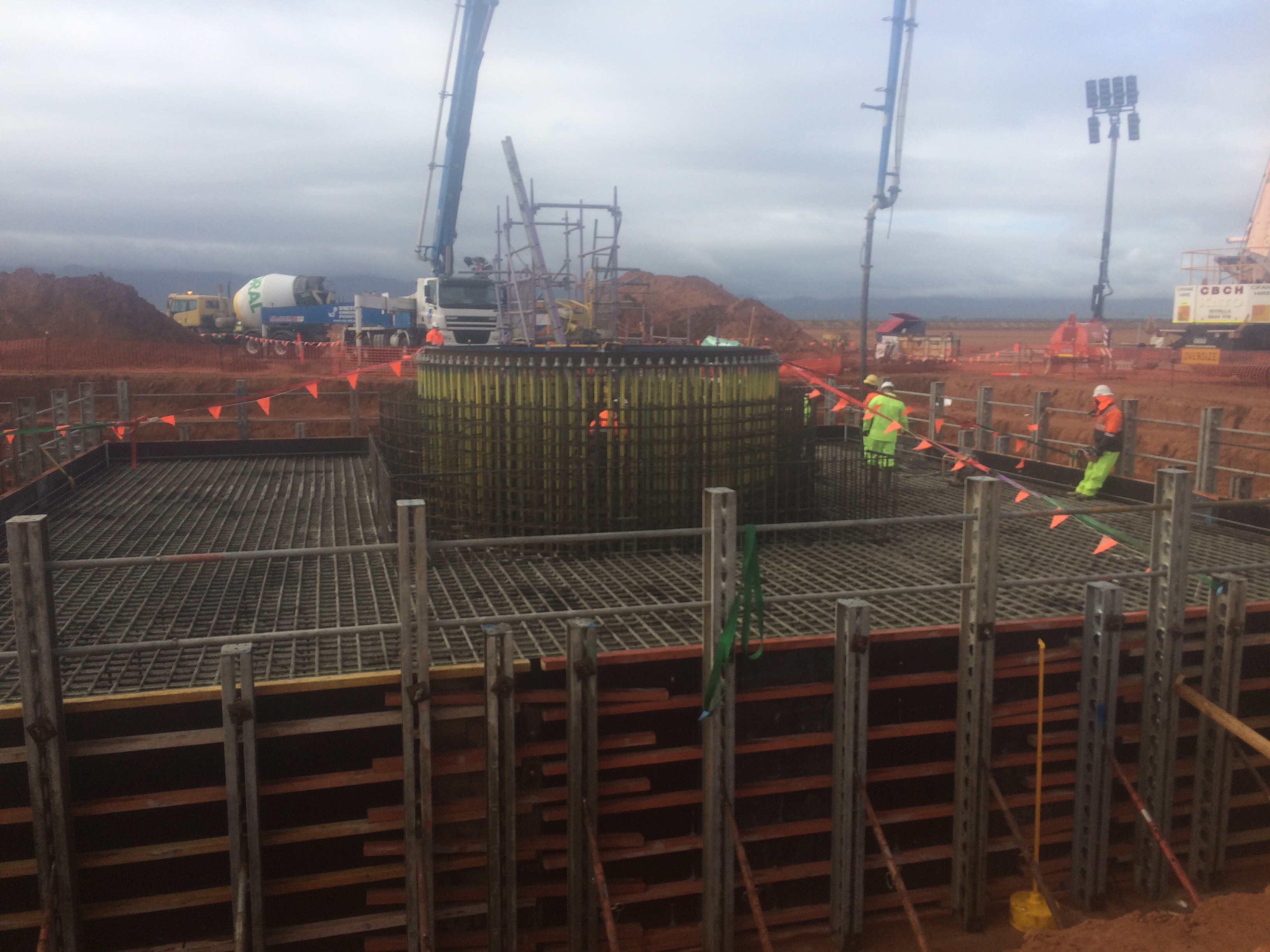
The big recent event on site was the pour of the Solar Tower foundations; I have included some pictures below for all the civil types out there. In total the pour was around 550mᵌ, it began at 0300hrs and lasted until 2000hrs. The planning and preparation involved in the whole pour was quite impressive and was greater than what I witnessed on some military operations, with standby pumps, plants and trucks identified across the state and put on reduced notice to move. Inside the reinforcement you can see the ring of 200 bolts, 4.5m long which will eventually hold the base of the tower. The photo’s below show the template holding the bolts getting lowered in to place, the start of the pour and the end of the pour (yes it is raining).
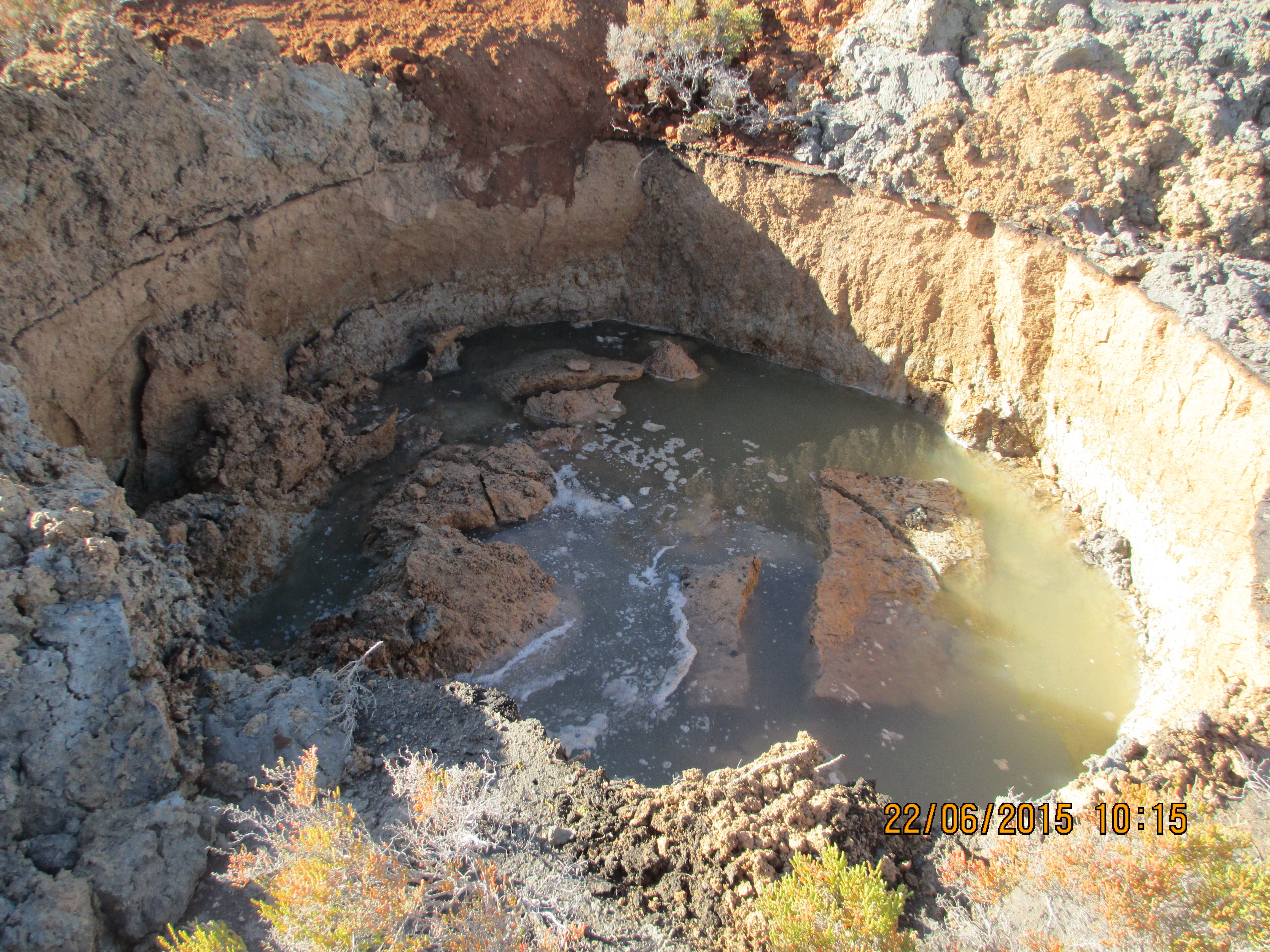
Other random things I have been running with include dealing with some asbestos that was discovered whilst excavating the pipeline writing an Acid Soil Sulphate (ASS) plan and the redesign the pipeline as it crossed through an area that locally has become known as the ‘bog’. The area in question was a concern as the pipe transitioned from an area of pale brown sand to an area of grey clayey sand before going back to sand. From John Morans lessons the mention of clay clearly sent alarm bells ringing in my head. As a result I was then tasked with organising a geotechnical investigation to try and establish an estimate of the long term settlement (which came back as 50mm over the 100m) and then amend the construction method and design to bridge the gap whilst ensuring there was enough flexibility to prevent the joints from opening up at a later date. All very civil orientated but I suppose it prepares me for future roles as a PQE in the Royal Engineers. What was a shock was the fact that this whole episode came as a surprise to everyone, despite the fact that the area can be clearly seen on Google earth. The photo below shows the result of a test pit, which started out as 1m wide by 3m deep trench about an hour before.
Oz PCH – Bomb Shells and Project Roles and Responsibilities Update.
Introduction
Almost at the half-way point through Phase 2 and having covered a lot of ground since AER 1, I thought I’d share the shaping (mostly by me) of my attachment. With regular DAP progress mtgs with my LM, the latest of which (17th July) the Building Services Director sat in on, he decided to drop a small yet not insignificant bomb shell – he has done his best Judas Iscariot impression by handing in his notice to leave JHG (in a month) to work for Westfield Construction (shopping centres). Not good news considering we are in the middle of commissioning, with issues popping up every day, and he is the Commissioning Manager!
The week prior we (the commissioning team) had a re-alignment of project roles and responsibilities. Interestingly my LM still had a hefty work load and was giving himself more! So you can imagine this has raised a number of questions, like; “Who is your replacement and will your position be gapped?”
Roles and Responsibilities
The following are my main roles with basic detail and examples where applicable:
1. System Availability Programme Analysis.
2. Fire System Integration/Cause & Effect Commissioning.
3. Building Performance Testing Management.
4. Performance Testing & Client Witnessing Programme Planning.
5. BIM 360 Field Commissioning Strategy Management.
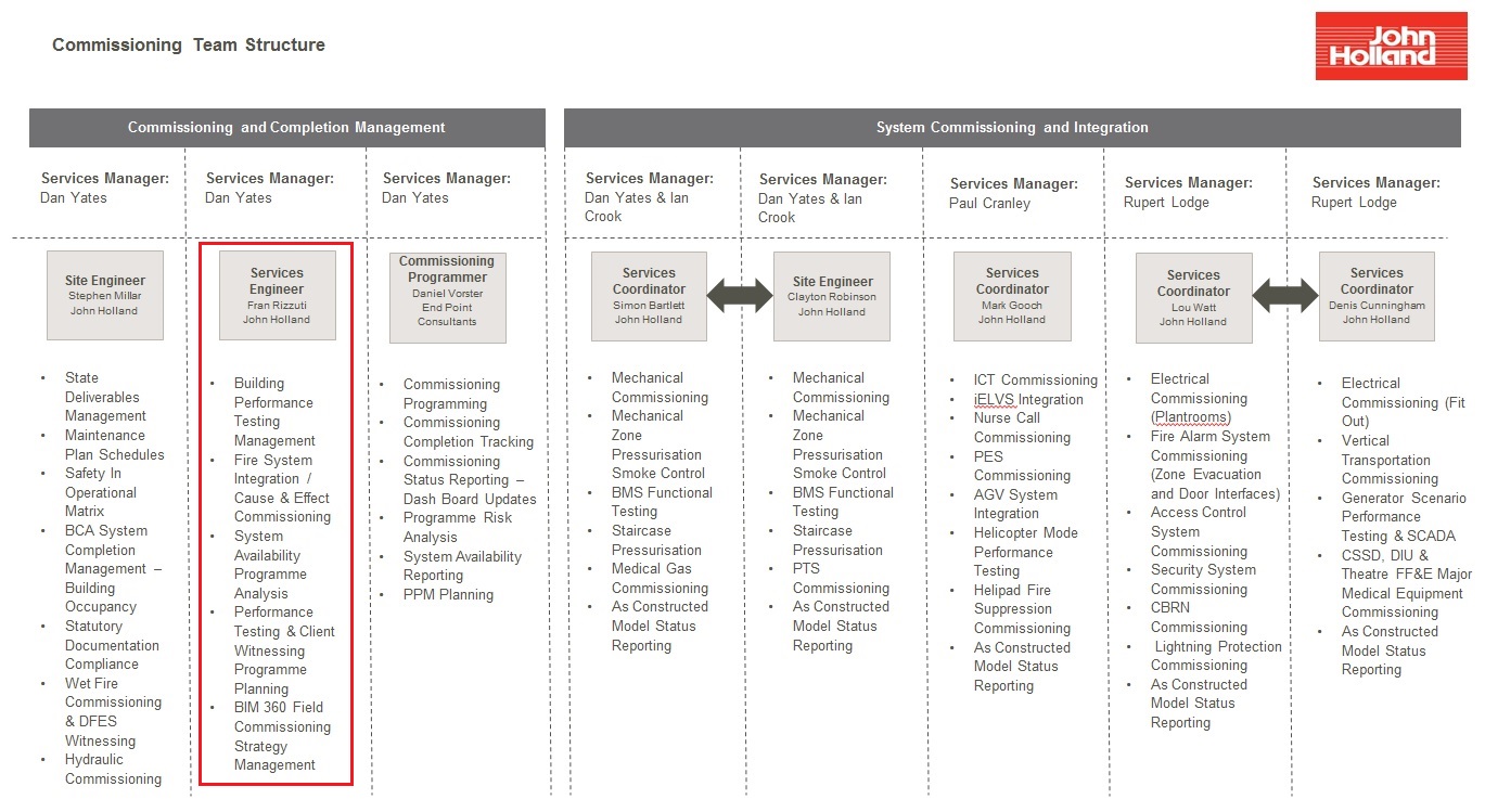
Figure 1. Commissioning Team Structure.
1. System Availability Programme Analysis
This consists of tying in the construction delivery programme with the commissioning programme. There are many factors affecting the ability for a system to remain ‘on-target’ for completion and therefore proves quite challenging to coordinate. A few examples are commissioning delays due to procurement issues; the lighting supplier experiencing manufacturing hold-ups and; late supply of the south side atrium façade affecting balancing of AHUs.
The latter example involved me searching through many detailed shop drawings and the Federated BIM Model to establish which air diffusers and grills are open to the atrium thus affecting the balancing of the AHU they are associated with. If the AHUs were balanced in their current state any building dust and debris would potentially contaminate the ductwork and would require cleaning all over again, not to mention give false air balance readings due to the large amount of air flow from the open space to the atrium. Figure 2 shows the current condition with the photo taken from the ground floor of the atrium with Levels 2 (Central Sterilising Services Department (CSSD)) & 3 (Operating Theatres) both open to the atrium. Both levels continue off to the left of the photo and present a significant opening.
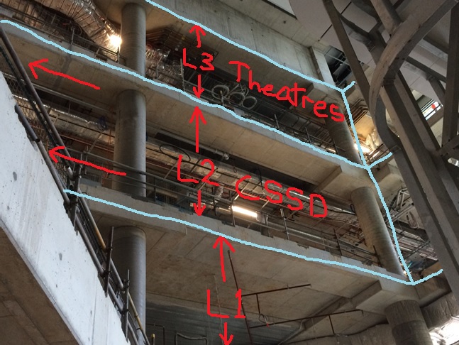
Figure 2. The Affected Open Levels to the Atrium.
The atrium glass façade fitted by subcontractor, Annapurna, is to be 90 mm thick and fire rated to 2 hours. Figure 3 shows the BIM Architectural Model of how it will look once complete (same angle as the photo in Fig1). Figure 4 shows the two levels from on top of the Level 1 balcony.
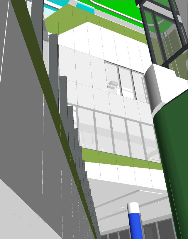
Figure 3. The Closed off Levels to the Atrium.
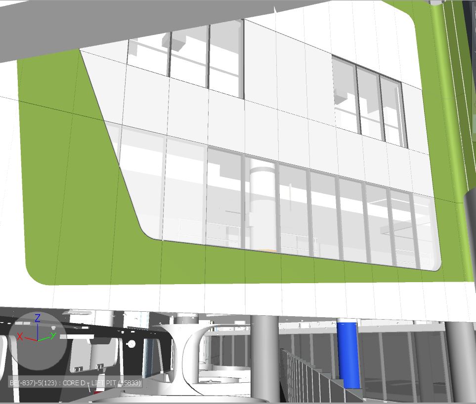
Figure 4. Atrium Facades in place viewing from Level 1 Balcony.
2. Fire System Integration/Cause & Effect Commissioning
This is a Cause & Effect Matrix based on a fire/smoke fault condition and explains what various systems should or shouldn’t do in a fire/smoke scenario. Fire and Smoke is just one of ten scenarios where the building is experiencing a fault condition. This particular Cause & Effect is quite complex especially when you consider that in normal operation mode certain rooms/areas are either negatively pressurised (infectious disease ward) or positively pressurised (operating theatres). Essentially the fire/smoke management system is stand-alone and hard-wired into various Variable Speed Drives (VSDs). These control specific AHU fans, fire and smoke dampers, wet and dry fire suppression systems and fire/escape door opening/closing systems. These are all monitored by the Building Management System (BMS).
3. Building Performance Testing Management
This is testing and assessing the performance of various systems and ensuring that they conform to Australian Standards, the design specification and ultimately meets the client’s technical specification.
4. Performance Testing & Client Witnessing Programme Planning
This is taking the above various performance tests and allowing the client to witness them. An example of which is the UPS room which will be covered in a separate blog.
5. BIM 360 Field Strategy Management
This consists of managing and coordinating the documentation and data entry of all commissionable systems into BIM 360 Field in order to meet the client’s requirement of Level of Detail (LOD) 500. This has meant creating a Commissioning Register in BIM 360 Field and a process that enables the commissioning team to track the progress of each system through its commissioning. Being a bespoke and innovative method of information management and integrating it with BIM Models has meant learning an entirely new way of doing business, one which has required deeper understanding of REVIT (CAD) Models and BIM in general so that I could conduct training workshops and aid the subcontractors in their understanding.
An additional task, which was confirmed in my latest CPD/DAP mtg by the Building Services Director, is for me to write up the BIM 360 Field Commissioning Implementation Plan for the PCH Project. Producing this document now may seem a little back to front considering we should have met Practical Completion in early July 15. However, BIM 360 Field was not procured until 2 yrs into the project and the original BIM Project Implementation Plan (by PDC) therefore had no mention of 360 Field. In addition, we are only now learning the challenges in its utility as a commissioning progress and information management tool. It will hopefully be similar to a lessons learnt document you might read from a previous operational tour; its intention to provide important information and help write a generic BIM 360 Field Commissioning implementation Plan. This will then aid JHG Corporate Staff in potentially combining it into a greater JHG Strategic BIM Implementation Plan. This gives me a great opportunity to re-inforce the recommendations that fell out of the conclusions I made in my TMR on BIM – What are the advantages of Building Information Modelling and how does its implementation allow John Holland Group to become the market leader?
In Other News
Han and I went to see Clarkson, May and Hammond Live at the Perth Arena. Excellent, with supercar porn (figure 5) and top banter aimed at the BBC for Clarkson’s Top Gear faux pas. The motorised lacrosse (figure 6), clearly car football but renamed for legal reasons to avoid Top Gear backlash, was hilarious even though the final score was Eng 4 – Aus 5.
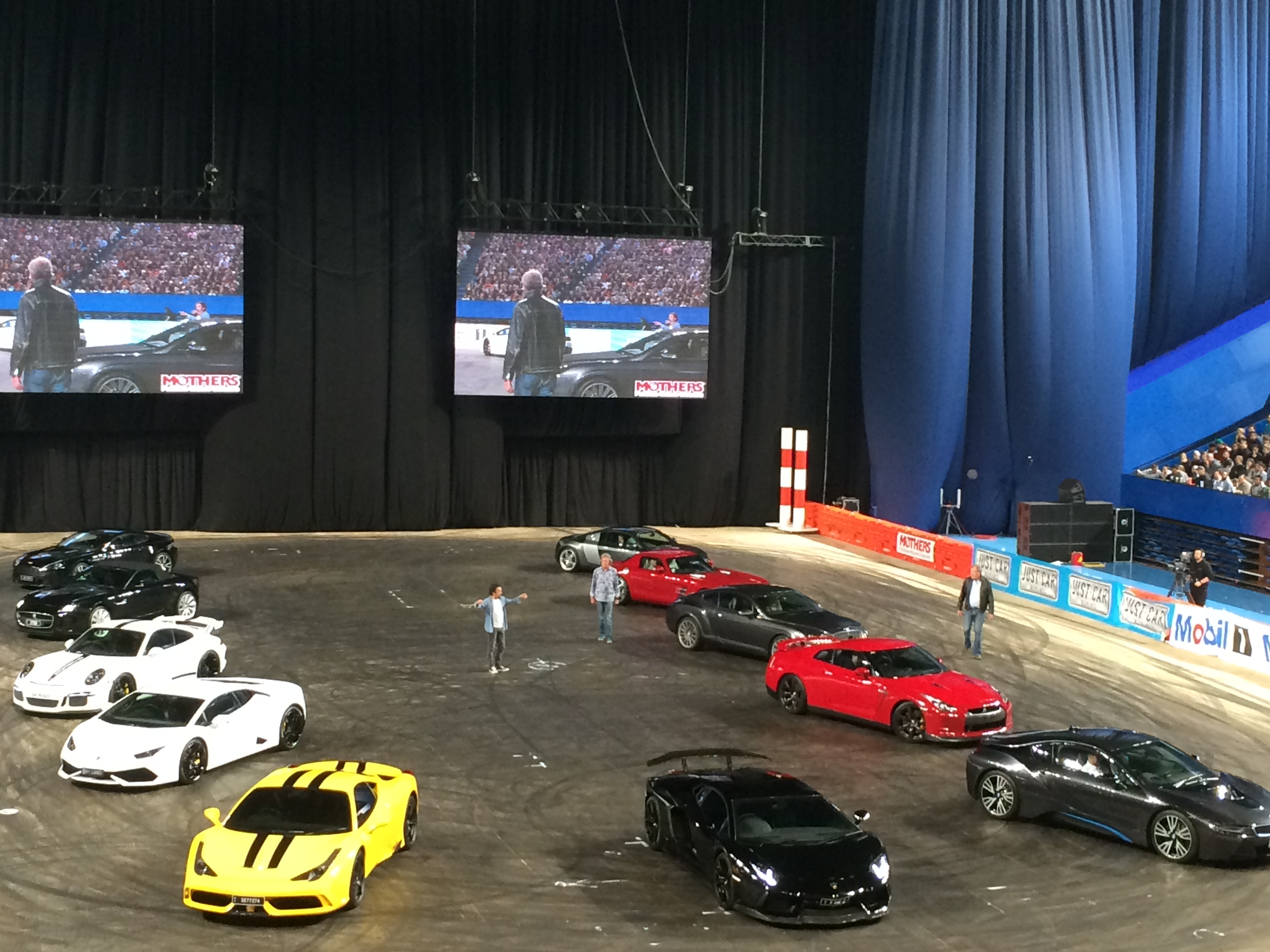
Figure 5. Supercar Porn.

Figure 6. Motorised Lacrosse.
Finally, and proving that even when you’re out on a social you’re always learning, I experienced an excellent example of an innovative carpark system. It is the underground carpark of the Perth Arena and as you can see from the photo in Figure 7 at the end of each row there are LED boards informing you of how many spaces are free in that row. Then when you turn in to that row you see a line of LEDs, red or green, with one next to each parking bay – the green ones being empty. Like Aleksandr the meerkat would say “makes finding a parking space simples”.
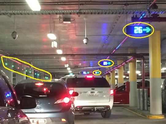
Figure 7. Perth Arena Advanced Underground Carpark System.
Making Neil proud
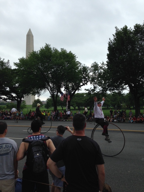
Today I have spent the vast majority of the day designing a bit of scaffolding. The scaffold will be used to attach a “Considerate Contractors” banner so that it can be viewed from the neighbouring railway station platform. It would be particularly embarrassing if millions of pounds worth of disruption to the railway was caused because a “Considerate Contractors” banner blew off it’s support and landed on the tracks. So no pressure then!
I started by considering the forces involved. Essentially the scaffold is required to hold the banner in place against wind loading, at which point I groaned at the thought and opened EC1 and the NA. After considering the elevation, distance in land, urban environment and all those other factors I hoped I’d never need again I then stumbled onto the clause regarding signs. Clause 7.4.3 gives you a coefficient to use when designing signs and the like. When applied alongside the seasonal factor for the length of time it will be in place it gave me a total wind load of 0.853 kN/m2. I checked it with Sam (our resident CEng) who said it seemed about right but that he’d never designed anything to EuroCode in his life.
My next step was to ensure that we could connect it to the scaffold. So I fell back on a skill I honed in Exercise Rhubarb Creek: I googled it. A 3M (TM) “Standard” Cable Tie has a breaking strain of 220N. I did a quick bit of maths and found that one tie would hold down a banner 190 metres long. Then I noticed it was in N not kN. So I had another go. 190mm, that’s more like it. The banner has holes every 450mm, so I needed to go bigger. A “Light Heavy Duty” Cable Tie has a breaking tension of 530 N. Each pair will support 460mm, so a tie top and bottom through each hole will hold it back.
Next came the scaffold itself. I decided on a horizontal bar top and bottom of the banner attached to 4 vertical bars at 2 metre centres. I tried desperately to work out the friction from a screw jack, but to no avail. So instead I just specified that each jack should be bolted to the slab/soffit and specified a bolt using the manufacturer’s data.
And there we have it. I’ve designed some scaffolding! They’re going to build it next week, I really hope it doesn’t blow away!

Bits and Bobs
Things are progressing in the usual manner so I’m going to summarise a few of points of interest from over the last week or so. In no particular order.
- I’ve inherited a Cadet this week. He is an exchange student, currently at the University of North Dakota studying Construction Management. He was essentially dumped in my lap late last week as the Lieutenant who is supposed to be looking after him is out this week. Since I am the only military guy in the office at the moment I went to the airport to pick him up and he is ‘reporting’ to me. Since it was pretty much out of the blue I’ve just been trying to get him inducted, fam’d up on the vehicle fleet, online and then sending him off to the Gym!
- The slides below were presented at a recent talk to the USACE by the Designer of Record (DOR) for one of the projects here. It is a risk assessment tool. I thought I’d stick it up out of interest for everyone to see as it’s something a little different to what I usually see.
Excerpt from DOR presentation. Step 1.
Excerpt from DOR presentation. Stage 2

Excerpt from DOR presentation. Stage 2
Excerpt from DOR presentation. Stage 3
3. There have been a few developments at the Central Utility Plant (CUP). I had an RFI come through about a column mounted Jib crane, which took me by surprise for a few reasons, not least because I didn’t know what a column mounted jib crane was. A quick Google search sorted that out. The next issue; there is nothing in the specs about the crane at all, or anywhere else, other than a note on the contract drawings giving direction about minimum hook heights, weight capacities, conformance to CMAA-70 and a requirement to swing 180 degrees. A cut from the drawing is below:
Excerpt from contract drawings.
Now, Damo has probably noticed that the crane appears to be mounted into the Web of the column; more on this later. Specifically the RFI that I got was to accept a proposed off the shelf solution. It contained some product data and drawings etc and requested that the RFI be sufficient for acceptance without a formal submission. I had a few reservations about this, I had also noticed that the crane appeared to be mounted in the web of the column. And that it appears to be over nothing, even when cross referenced with other drawings. I sent a question to the client asking what the intent of the crane is but have thus far heard nothing. Nobody here seems to know what its for either.
The designer reviewed the RFI and had no issue with the actions that the crane would impose on the column but I still had misgivings, specifically with regards to how the Contractor was intending to mount the crane (welded plate I guess) and maintain the 180 degree reach. I therefore asked for a formal submission with the connection details articulated more clearly than a manufacturers drawing which, in my opinion, won’t work as required. I spoke with the Contracting Officer’s Representative about this because the designer will be able to charge to look through the submission because it will be out-with the originally agreed submission requirements.
4. Specialized (sic) Engineering are the QC sub-contractor that conduct tests such as concrete slump, soil compaction, weld integrity and the like. For my structure they are required to come and check bolt tension, weld and plumb of the building. The most interesting thing, for me, of the last Specialized visit was the apparatus used to test the plumb. The Bazooka bob is an enclosed steel tube with a string tied at one end and measured increments at the other. It extends out and attaches to the steel magnetically. It is 10’-5” with increments of measurement of 1/8th of an inch at the base. A measurement of 2/8” at this distance represents the 1/500 allowable deviation from vertical so if the string falls outside of this you know that the column is deficient. Simples. All the measurements taken on site were within tolerance.
- The cooling towers (a mechanical feature which will eventually sit in the CUP) submission is being bounced around from Principal Contractor to USACE to Client to USACE to… The proposed towers (by the Principal Contractor (PC) were submitted a while ago and returned as deficient with c. 21 comments. The PC re-submitted the same towers with, what I consider, rebuffs to the client comments. I was in a meeting yesterday where the client essentially ‘kicked off’ at the situation questioning why it was that clearly erroneous submissions were being sent in, especially since the crux of the issue is that the cooling towers proposed are so far away from the Basis of Design (BOD). Again the PC had an answer along the lines of “we can ask for a variance to the BOD,” to which the client pretty much said “provide what we ******* ask for in the specs.” Fair enough – it was a heated meeting. This is interesting, not just because of how stubborn the PC is being but also because the cooling towers in the BOD are anchored to the steel building at 12’ centres. The PC preferred towers are anchored to the building at 14’ centres. You can no doubt guess at what spacing the steel frame has been erected, snapped, decked and welded.
- Another BOD issue; I am lead LEED representative at the moment whilst the actual lead LEED lady is on maternity leave. (LEED is essentially the same as BREAM). I have split responsibilities with another guy from the office who is also here temporarily. I reviewed my section (recycled content and regional materials) and had a scan through the rest of the submittal before passing the it to the other guy. I noticed that the PC had made a comment that they were making no effort to submit the 3rd party VOC certification required by the specs for Environmental Air Quality because the material suggested in the BOD didn’t come with it as a matter of course. I gather that they got this information from speaking to the manufacturer named in the BOD. I advised him to ‘E code’ (re-show) the submission and request the PC to send of material to a 3rd party lab for testing and certification. What interested me about this was that the material and manufacturer named in the BOD wasn’t compliant with the specs as a matter of course. I am waiting out to see if the PC gets back to me on this issue or if they will just send the material off for testing. The cooling towers issue hints at the former.
- Another area of contention has been due to backfilling activities (and I mean to echo Guz’s sentiments about good and bad engineers, but also add in ‘Lucky’) For me the issue started when I spotted a sub contractor backfilling some utilities into fairly wet excavations. What didn’t help was that there was water ponding in the weld pits and there was no effort to remove it prior to backfilling. To me this seemed ‘a bit weird’ as a gut reaction although admittedly I wasn’t clued in on the method of backfilling in the specs. I made a call to the PC and said I think the water should be pumped out of the weld pits as a minimum, prior to backfilling, and went to lunch. When I got back from lunch someone from the mechanical team came up and shook my hand for a ‘good catch.’ Apparently what I had witnessed was out of spec (shock) but also another in a long line of deficient practices with respect to the placement of utilities. Whilst I was at lunch the civils project engineer went to have a look at the site, taking along with him 2 other QA reps and some of the mechanical team. The PC superintendent noticed the collection of people and called his QA team . The PC was requested to prove that they had been backfilling properly to which one of their team jumped into the excavation and promptly sank in soil, which was presumably not within 3% of the optimum moisture content called for in the spec. This is an ongoing issue which could well form the basis of a TMR but the point I make here is to echo something I am sure I have heard around PEW but I cant attribute it to anyone in particular; if something doesn’t look right, it probably isn’t. I was fortunate to be passing by the activity when it happened or it mightn’t have been noticed.
In other news: This.
Two Fifty One – Learning Simple Lessons (commercial x 2 and drainage clashes).
Two Fifty One – Learning Simple Lessons (commercial x 2 and drainage clashes).
Off hiring. As a way of reducing site clutter I arranged with the plant hire company (Select – an internal within Laing O’Rourke) to off-hire some RMD soldiers and Haki stairs.
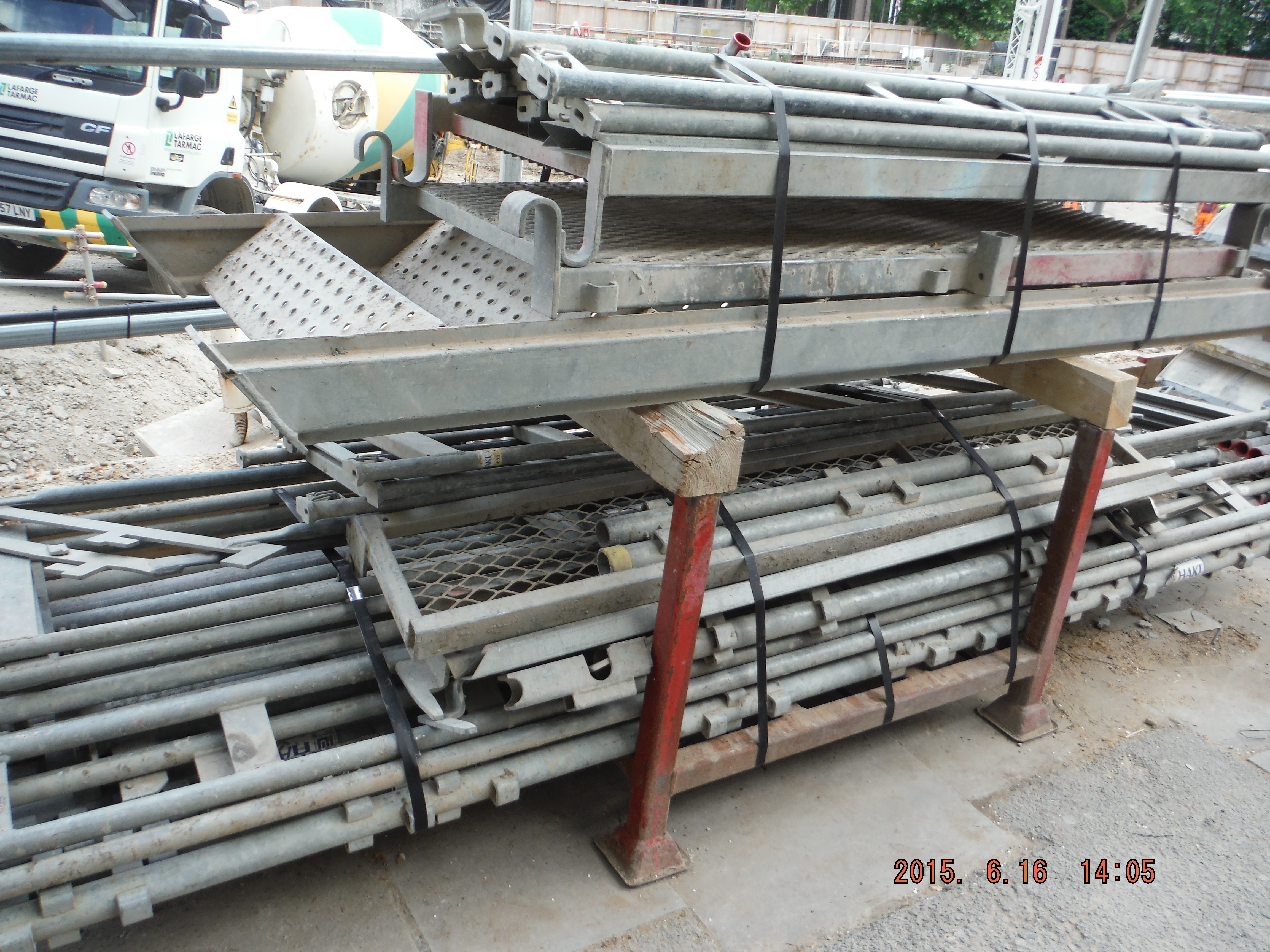
Haki stairs for off-hire
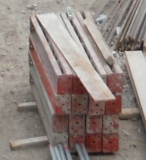
20 RMD soldiers for off-hire
Simple and straightforward intent. Clearly getting rid of equipment would also mean the items are no longer paid for. So a few days later a 40ft low loader arrives from the plant hire company to collect the formwork. Utterly ridiculous size vehicle to remove the items which are small as shown above. A couple of weeks later and we receive a £300 collection bill! So in theory it would be cheaper to keep the items on site for months, than return them.
In short, the message is don’t forget about transportation/mobilisation costs of equipment. Albeit not a bank breaker, but a useful lesson early on.
Take off take offs.
Discussed on blogs recently was the subject of calling off drawings. I’ve called this “take off” here. Within the Two Fifty One project, my next focus is to plan the installation of the basement drainage. It is not a big job; the square area is about 1900m². However, having had the drainage runs priced from the drainage drawings by a Quantity Survey it makes sense to use their lengths and itemised totals as a check against the materials supplier totals. Lesson here is (I hope) that generally a lot of the length, area and volume calculations have already been completed for the project; therefore there is no need to repeat all of the work. However, caution must be applied to blindly assuming all is correct, designs have not changed, and it was priced correctly in the first place. Lesson – speak to the QS team (they aren’t just people who say no to all material orders!)
Drainage Clashes
The Two Fifty One development’s basement is founded upon 300 plus piles split between a raft pile cap for the tower and a series of smaller pile caps for the office. There are also two tower crane bases within the basement area.

General arrangement pile cap layout
The drainage design was produced on a standalone drawing with neatly drawn foul and surface water runs spanning between manholes.
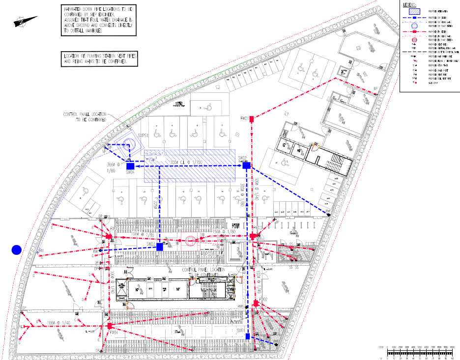
Drainage layout
Overlaying the 2 drawings (pile caps, tower crane footings and drainage) highlighted 6 pretty obvious clashes.
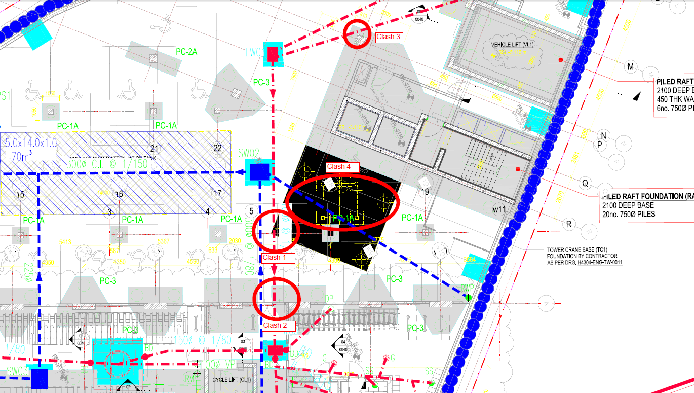
Clashes identified (1-4 shown).
3D images exemplify issue:

Clash 1 and 2 – Drainage run with corners of pile caps
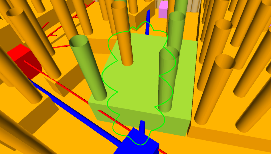
Clash 4 – Drainage run with tower crane base
I would think, as the designer was asked to do the overlay, they would have amended the layout. Nope and in fact the designer warned us (contractor) that these changes may delay the issue of the reinforcement drawings! So an RFI later, a much improved drainage layout was produced.

After: Clashes resolved (1-4, noting 4 sits better regarding position of tower crane base)
Without wishing to get into another pre-novation discussion, the time to resolve this issue is at the client’s cost (main contract still not signed so design risk currently sits with client). So I hope this will yield success in about a month when the drainage installation starts.
Change!
Since my last blog about the Fort Indiantown Gap progress has been slow. This appears to be as a result of the difficulty from the contractor’s end both in meeting USACE’s various contractual requirements for personnel and an ill defined scope. Following a theme of designers not confirming what is currently in place prior to starting refit designs this had lead to a protracted series of RFIs. Finally to curb this laborious process this week I managed to get everybody into the same room, except for the designer who phoned in, and we managed to thrash through the details.
The issue has come down to the hot water distribution. The original system is shown below at Figure 1 with three separate pumps feeding individual systems. As the H&V unit was removed years ago the demand on P-3 has reduced from 52 to 0.75 Gallons per Minute (GPM). This means it is massively oversized but the designer had just replaced it, he had also labeled it as P-3 on the Boiler Detail (Figure 2) and connected it as if it was a stand-by pump: hence the contractor’s confusion!
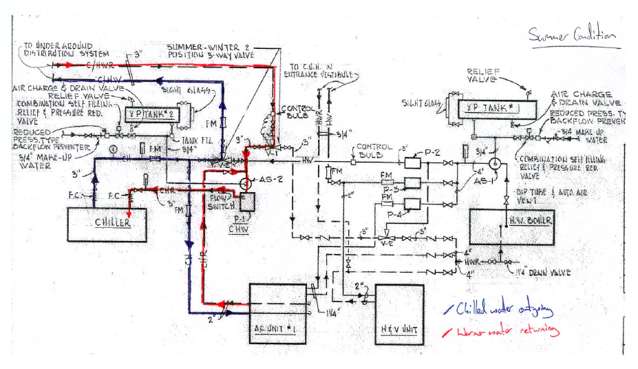
Figure 1: Original System
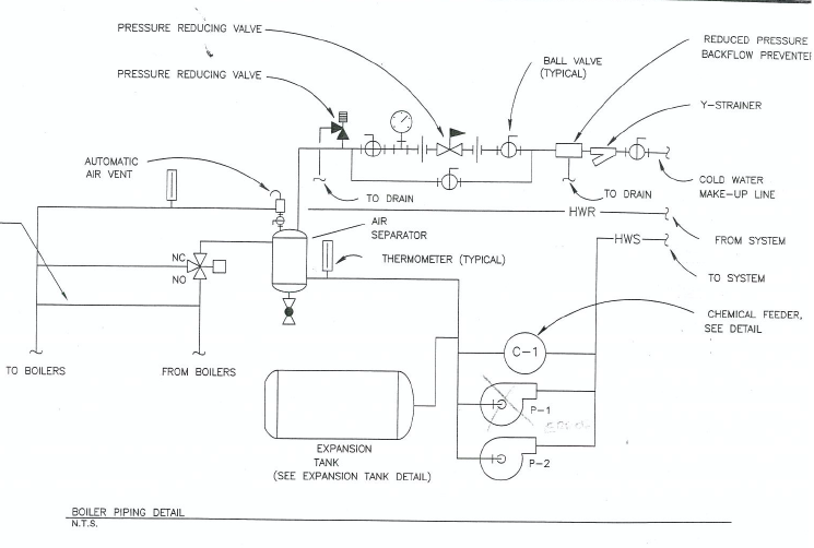
Figure 2: The original replacement design
So as a result of our meeting the contractor and I came up with Figure 3, proof that pen and ink isn’t dead! The other clouds are described below in my contract modification.
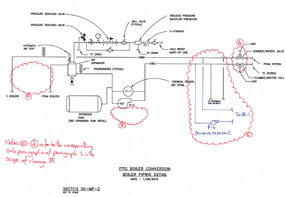
Figure 3: Modification Drawing
‘The boiler piping detail shall be replaced with attached sketch MP-2. This modification includes the following:
a. Removal of the three-way valve (known as V-3) from the hot water return to the boiler as it is not required.
b. Removal of P-1 from the detail. Given that the majority of the load for P-3 (H&V unit that has been removed) no longer exists P-3 shall be removed and the remaining active load added to pump P-2. New total for pump P-2 shall be 111 GPM, the pressure drop will remain as currently scheduled given that the distribution system is the longest run.
c. Hot water piping serving CUH, located in the vestibule, and AC-1 shall be connected to the new hot water piping before the summer/winter change over valve such that it does not receive chilled water from the dual temperature side of the system.
d. Two automatic three-way two position valves are to be included as the summer/winter change over valves. These will switch between the hot water supply and return and the cold water supply and return respectively.’
So what?
This is proof to me that the PEW attachment process works, the original system was not designed to be constructed; instead it was treated as a paperwork exercise. This is probably reminiscent of a few Crosby design exercise submissions, however in my defence there wasn’t a building to walk around and design to.
Another valid idea might have been to increase the size of P-3 and turn it into a stand by pump, however the spare budget for this project is small and needs to be preserved for when problems start occurring in construction so we used the cost saving from this to ‘wash’ against the cost of the automated summer/winter changeover valves. Next stop for this modification is a few stamps from the hierarchy and then into negotiation which should be interesting.
Schedule
Another element of the meeting was to review some of the contractor’s submittals that required changing and this included the project schedule. Fig 4 shows my copy of their schedule prior to the meeting. It is probably difficult to see all the detail but the best part is where the contractor has claimed a value of $120,000 for boiler removal and $45,000 for insulation removal, bearing in mind this is a $500,000 contract. The boiler removal will require skilled personnel and some Materials Handling Equipment (MHE), but the insulation removal will just be Spr Crosby with a knife and a bin; so $4,000 and $1,000 might have been more appropriate. When confronted as to why the project manager, without a hint of shame, said: ‘That’s frontloading.’ I’m not sure whether Steve Payne would be proud or ashamed of him but, needless to say those figures will be adjusted.
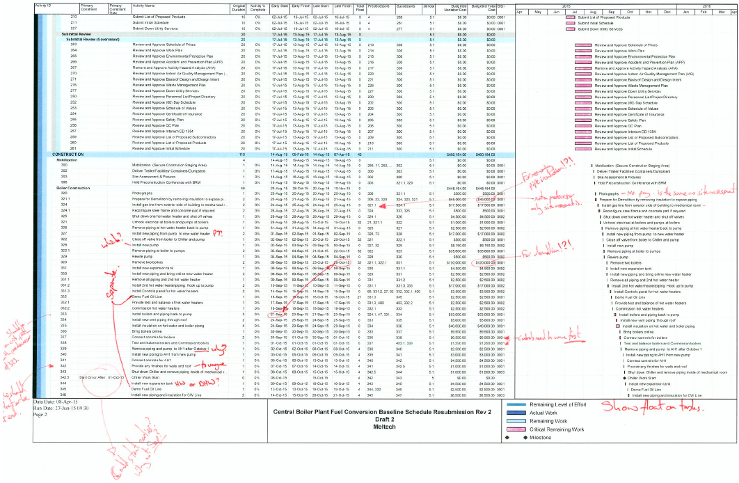
Figure 4: Schedule with my notes.
Looking further into the actual scheduling issues there is little structure which has caused issues. There is a requirement to maintain continuous domestic hot water throughout the project and space is, as ever, tight. It appears to me that no attempt at a Product Breakdown Structure (PBS) and Work Breakdown Structure (WBS) was made which would have aided sequencing of this job.
Signs
The only work that has actually happened on site is the erection of the project signs as shown in figure 5 This also shows a lamppost, and a High Voltage (HV) Ring Main Unit in the background. The consequence of locating the project sign so close to the lamppost and HV Ring Main Unit could have resulted in death as a result of cable strike when digging the postholes. Fortunately, no one was injured in the erection of the sign. As well as the potential outcome for the contractor’s employee erecting the sign, contractor has also not asked for permission to dig. Therefore I took the action of writing a warning letter in order to warn the contractor’s senior management of the error. Also, as this was the first actual work on site, the letter catalogues the error so that, in case further H&S violations are witnessed, there is evidence to remove them from the site.
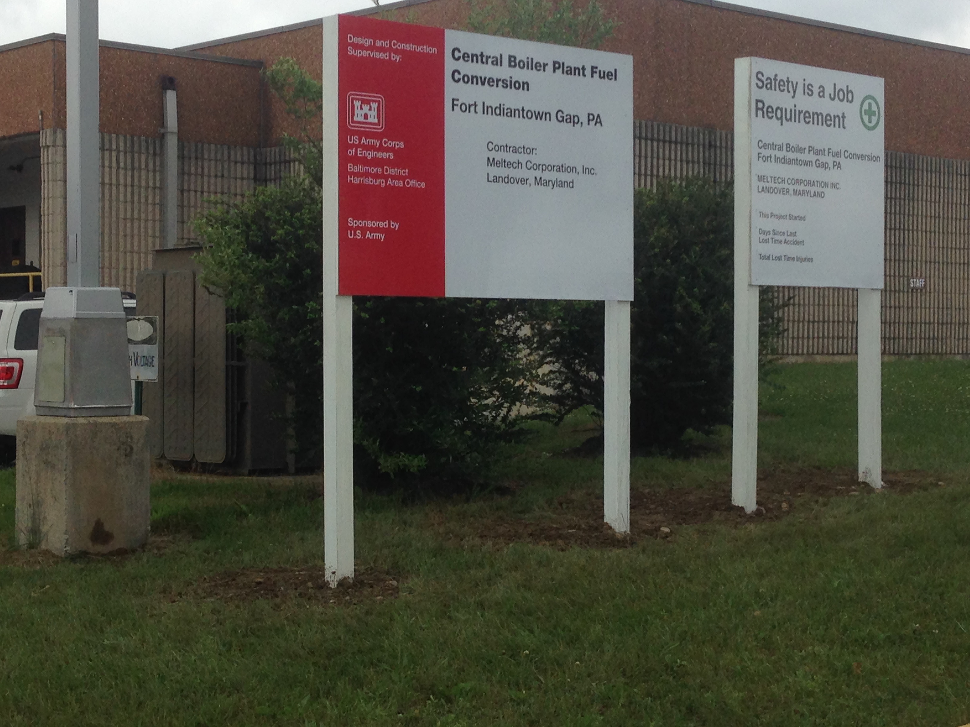
Figure 5: Spot the H&S risks!
Oz PCH – The BIM 360 Field Application and its use in Commissioning.
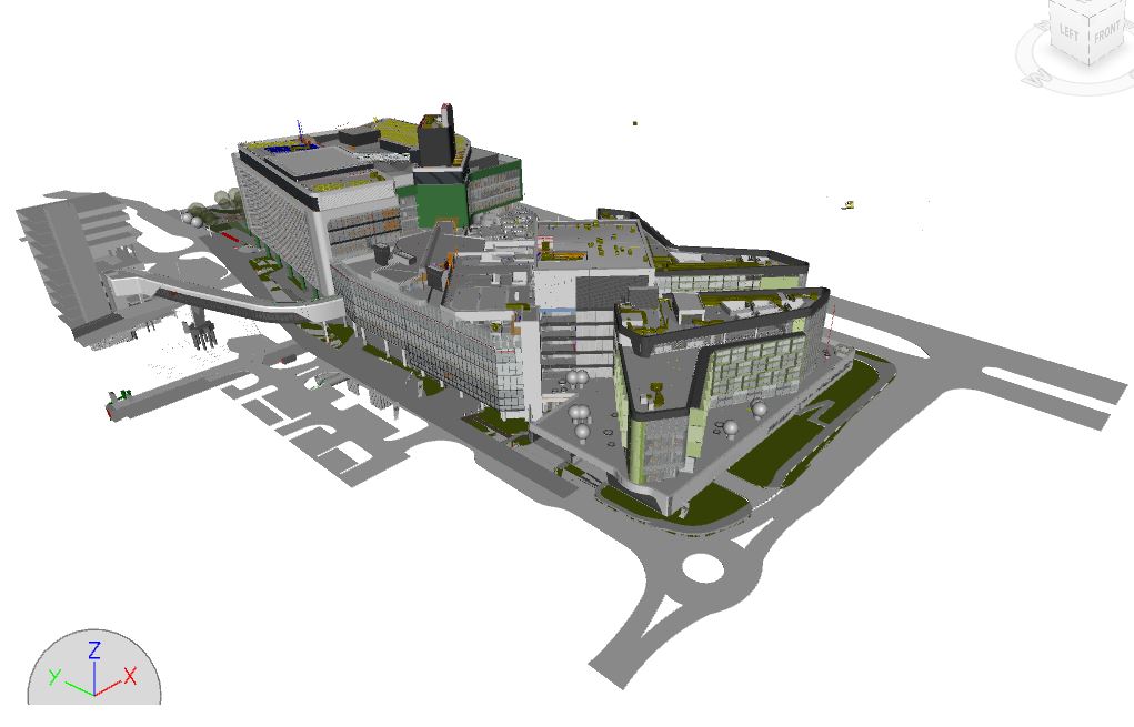
The PCH Federated BIM Model
Introduction
Continuing on from Olly and Howard’s blogged experiences with BIM, I thought I’d add mine too. From the sounds of it I have been a little more involved in its use, or I should point out it’s one of my roles and responsibilities of the project. This has meant I have had to understand BIM in its wider sense/application (hence I decided on BIM as my TMR 1 topic) and therefore grapple with it on this project. Due to various complexities and getting a brand new process up and running I have waited till now before blogging about it.
Why BIM?
Throughout the lifecycle of a project BIM based models continuously develop with vast amounts of information requiring data entry. This increased development of information is used to measure goals and milestones and is referred to as Level of Detail (LOD). There are six LODs; 100, 200, 250, 300, 400 and 500.
The Client (State of WA) required the use of BIM and in line with their Technical Brief JHG are to provide LOD 500 (A Facilities Maintenance and Management Model (based at BIM maturity level 3) for all equipment within the Federated BIM Model. This will be achieved through the utilisation of Autodesk’s BIM 360 Field application (BIM 360 Field is the QA/QC application used in construction, on-site in the ‘field’). The implementation of BIM 360 Field on this project is cutting-edge and so to my knowledge has never before been attempted anywhere in the world to this level on such a scale and complexity. Apart from ceiling and wall closure sign-off, the use of BIM 360 Field for the commissioning of building services is being implemented in a novel way and stretching its capability into unchartered territory. Mapping equipment in the Federated Model to all test, commissioning, operational and servicing documentation is vital to meeting the LOD 500 requirement. This not only serves as an electronic repository of as-built information but also aids in the Facilities Maintenance (FM) Management of all building services systems throughout the 24-month Defects Liability Period (DLP) and remaining lifecycle of the facility.
The aim of utilising BIM 360 Field as the means to linking this information is due to its technological superiority over other information management systems and to enable the PCH facility to accommodate future flexibility. It also aims to allow JHG to build upon their BIM implementation experience for future corporate knowledge and growth. This is all in order to satisfy the building services commissioning plan and to ensure LOD 500 is met.
Analysis of JHG’s BIM Implementation Strategy
The requirement set out above was always known from the start of the project however the use of BIM 360 Field as the management tool was not…
From the outset the well-established use of BIM for model collaboration and clash detection was adopted (BIM level 2), as this was a client contractual requirement based on its scale and complexity. JHG acknowledged their lack of BIM experience and so in order to implement it effectively they identified the need to utilise a specialist BIM consultancy service. CSI Global Systems, with a contract worth AUD$1.5 million were to devise a strategy, implement and manage BIM for the project. This investment was in addition to licence fees and hardware.
JHG’s intention is to use the PCH project, being the first to adopt a BIM strategy, to help shape the way they see BIM adoption across all business sectors from a strategic level. From an operational/project point of view BIM implementation works very well with the various models collaborating together and using clash detection effectively. However, on a tactical/detailed level there have been some extremely challenging aspects as the following decision timeline over the expected four-year project explains:
- Dec 2011 – Project Start Date.
- Jan 2012 – QA/QC Manager requests for a defects management tool (BIM 360 Field researched and proposed).
- Dec 2013 – Decision to trial BIM 360 Field finally granted.
- Feb 2013 – Trial completed with the use of iPads.
- Apr 2013 – Implementation of BIM 360 Field on wall and ceiling closures (aided by additional hire of a BIM consultant).
- Jun 2013 – Web programme and application of BIM 360 Field designed with students’ help through designing Application Programme Interfaces (APIs) thus allowing uploads of data mapping to the federated model and 6D elements.
- Dec 2015 – Estimated Practical Completion.
BIM 360 Field used for raising issues and as a defects management tool (its intended use) works extremely well as does the ability to have this data displayed on a dashboard through the BIM 360 Field web application. Many challenges came as a result of the late procurement of the application and therefore were not planned for in the implementation strategy. These were; lack of understanding, training and competence in its use in delivering the additional requirements of meeting LOD 500 (6D FM) (at maturity level 3); and data mapping to the federated ‘as-built model’. These are still causing issues but the biggest challenges are software design glitches. The BIM 360 Field application has been developed by Autodesk for the construction industry specifically to aid in transforming the way in which data is collected, connected, visualised and managed. It extends the benefits of BIM to the construction, commissioning, completion and facility management processes. However, the reality of utilising BIM 360 Field is that Autodesk had never used some of its features on a project of this size and complexity before and as such it could be argued they are using the PCH project as a test-bed for future enhancements. This has created numerous issues that have in reality hindered the application’s perceived benefits.
Initial Implementation Issues
Overall the keys issues/limitations of adopting BIM 360 Field have been:
- Late implementation (by approx. 2yrs).
- Little to no resources allocated for its dedicated implementation.
- Extra requirements added; LOD 500 6D (FM) and links to federated model.
- Poor/little implementation strategy.
In conclusion JHG’s initial BIM implementation strategy was sound, utilising BIM consultants due to their lack of BIM knowledge but particularly due to the complex nature of the project. The implementation at level 2 was coordinated well and continues to provide tangible benefits however the BIM 360 Field application proves to be challenging in delivering LOD 500. Maybe adopting BIM 360 Field from the outset with increased resources, education and training or on a much smaller project first could have helped ensure better success than what is being experienced at present.
BIM Model Structure
BIM 360 Field Strategy Management – What have I done?
The Problem
We (the commissioning team) have been instructed to use BIM 360 Field for commissioning management and coordination across all commissionable systems throughout the project. This poses many challenges (as above), the key ones being:
Late Adoption. Due to late adoption, the BIM consultants (PDC) who wrote the BIM implementation plan for the entire project and who manage the Federated Model didn’t include the use of BM 360 Field. This means there is no strategy to follow and therefore from a technical point of view proves challenging to understand and ultimately costs time.
Lack of Understanding. How to utilise BIM 360 Field for commissioning related activities. This has meant experimentation and the process evolving as and when problems arose and were then subsequently resolved.
Lack of Support. From a technical perspective by Autodesk and from a commercial perspective by JHG in terms of manpower and financial resources.
Although BIM 360 Field has BIM in its title (how Autodesk packaged and sold it), it is nothing more than an information management tool. It allows the commissioning team and managers to view information and documentation flow according to the process. This is not part of commissioning per se but is the background administration necessary to enable interrogation of the commissioning register and find out what may be holding up the commissioning of services systems. This then aids us by creating efficiency in directing our focus on a particular area, important on such a large project with so many diverse systems, to solve a particular management or engineering issue.
Considered Options. With limited experience in the use of BIM 360 Field and what the application could offer, various options were difficult to conceive and so the commissioning team could only review the processes that were set-up for ceilings and wall closures. These processes relied upon the use of checklists updated via iPads in the ‘field’ by either the delivery team (building services coordinators) or trade contractors responsible for that area. There were many additional implications to consider when applying the same process to commissioning; primarily due to the requirement to commission by system rather than a specific area. Commissioning by system area delineation, rooms, zones and floors would have been a difficult undertaking especially as some systems are part installed by more than one subcontractor. The biggest challenge would be identification of issues as commissioning progresses so they can be efficiently resolved. This means having a robust information management system in place.
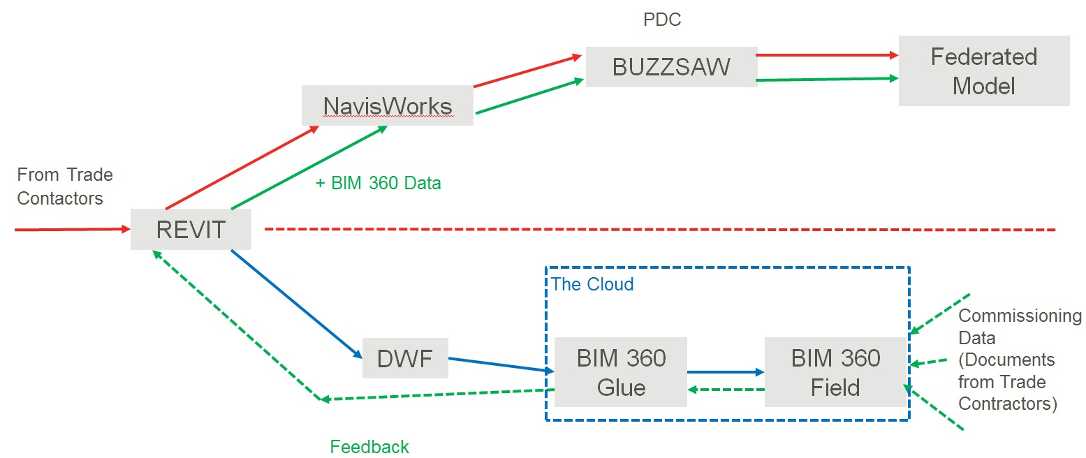
Chosen Solution. We decided to utilise bespoke checklists accessed through the iPad and created a Commissioning Register (spreadsheet) that acted as a commissioning progress (by system) display. The Commissioning Register is linked to the equipment in the BIM Federated Model through BIM 360 Glue (the software that links data from BIM 360 Field back to the ‘cloud’ and processes it back through to the original REVIT Model) and so when checklists are updated they subsequently update the Register thus displaying progress based on the traffic light system. More importantly, any issues that arise along the way are captured (through iPad use) and allow us to resolve them to closure. A key part of the solution was the communication of it and how we intended to implement it.
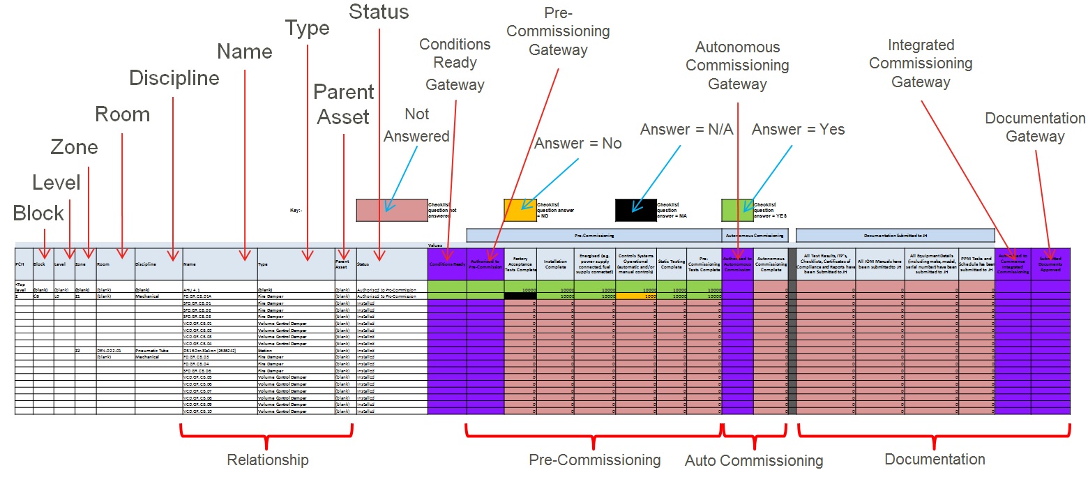
Commissioning Register – updated directly from BIM 360 Field inputs.
Justification. This was based on the need to find the easiest most efficient way of meeting the requirements as set by the Client and one that could be easily communicated to all involved and thus understood.
Implementation. We came up with a strategy to implementing our solution to the problem, the detailed process and what steps we took to get buy-in from both the JHG project delivery team and trade subcontractors. In summary it consisted of a greater understanding of BIM 360 Field and its capabilities, production of a commissioning management process, a Commissioning Register (for progress reporting) and a number of presentations communicating our coordination plan.
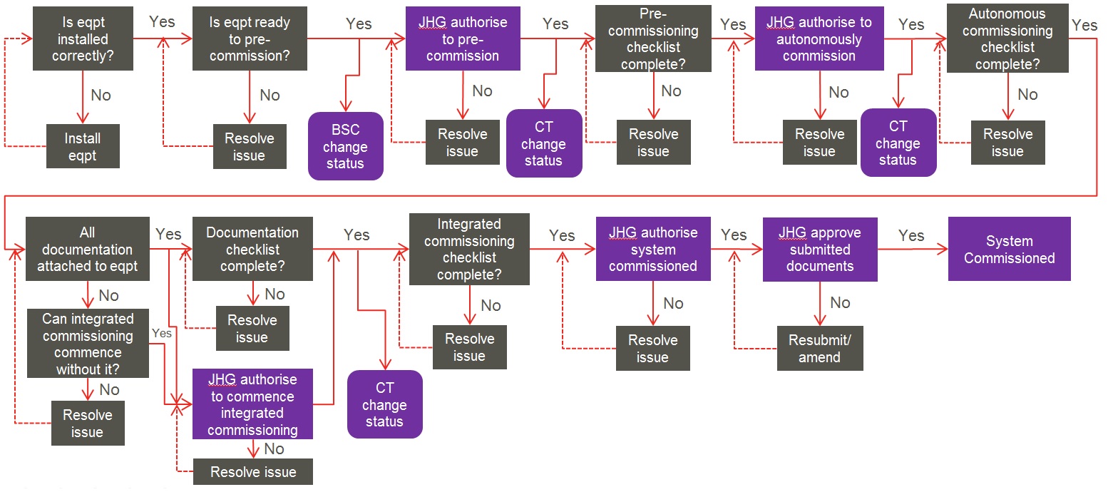
The Commissioning Process.
Associated Costs. The investment required was relatively small totalling in the region of AUD$330,000 for the Autodesk licence, consultant and data handling fees. What is more difficult to cost is the time spent in developing the process with multiple individuals and teams involved.
Food for thought
It would be interesting to hear other users views on BIM…
Upcoming ICE Event
The ICE are hosting the following conference at link below which seems very interesting. I wonder if anyone from the school, current Phase 1 students might be going.
ICE BIM 2015 – Realising the Promise Conference.
Illegal Steel Erection
Firstly – Nice job Guz, Swimmer and Fat-Bloke.
The Coffee CUP is nearing completion of sequence 1 / 4 structurally. In the main things have progressed smoothly, with the odd schnell evacuation due to the recent thunderstorms. Minor glitches include the incorrect placement of anchor rod bolts which attach the baseplates of the columns to the rc pad foundations. This was a quick fix with the erroneous bolts cut down to the profile of the bottom of the base plate (essentially so the base plate was resting on top of the cut down bolts) and new HILTI bolts epoxied into newly drilled holes in the correct location.
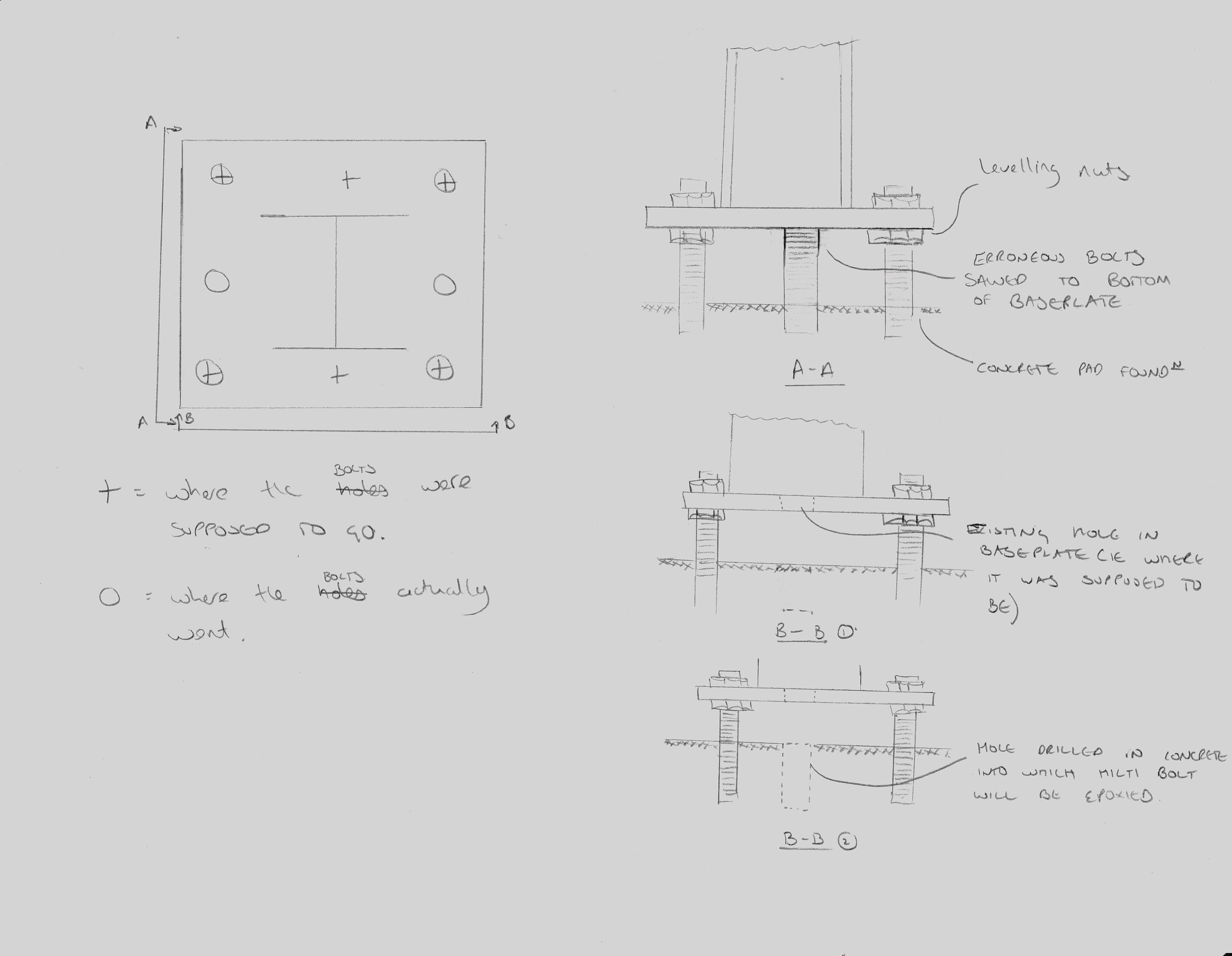
Sketch of Baseplate anchor rod correction
The washers used at the base plate location also need replacing with larger ones so that they entirely cover the drilled holes in the base plate. This will allow any uplift forces to be properly distributed to the baseplate through the entirety of the washer.
A more serious problem arose at the placement of a double bolted connection. A double bolted connection is essentially a shared connection between two beams on opposite sides of a single column. This is a fairly common connection type however the method of erection is supposed to be controlled for safety reasons. This is stated by the Occupational Safety and Health Administration (OSHA) para 1926.756 and also in the USACE HQ document EM385-1-1 at OSHA and EM385-1-1 (Cl 27 E)
Erection in a manner contrary to these documents is essentially illegal so in order to prevent the issue correct erection methods are stipulated in the contract documentation (spec) and checked for in the steel erection plan submittal which is required by the government before work can start. In cases where shared connections exist there are three standard ways of staying compliant with the regulations. These are sketched (crudely) below but are 1. Cut outs in the end plate. 2. Staggered end plates. 3. Welded or bolted shop or field attached seats. These methods are designed to either support the first beam directly or by allowing the minimum single snug type nut and bolt to remain in place whilst the second beam is flown into position. This removes the risk of the first beam slipping its connection and falling during the process.
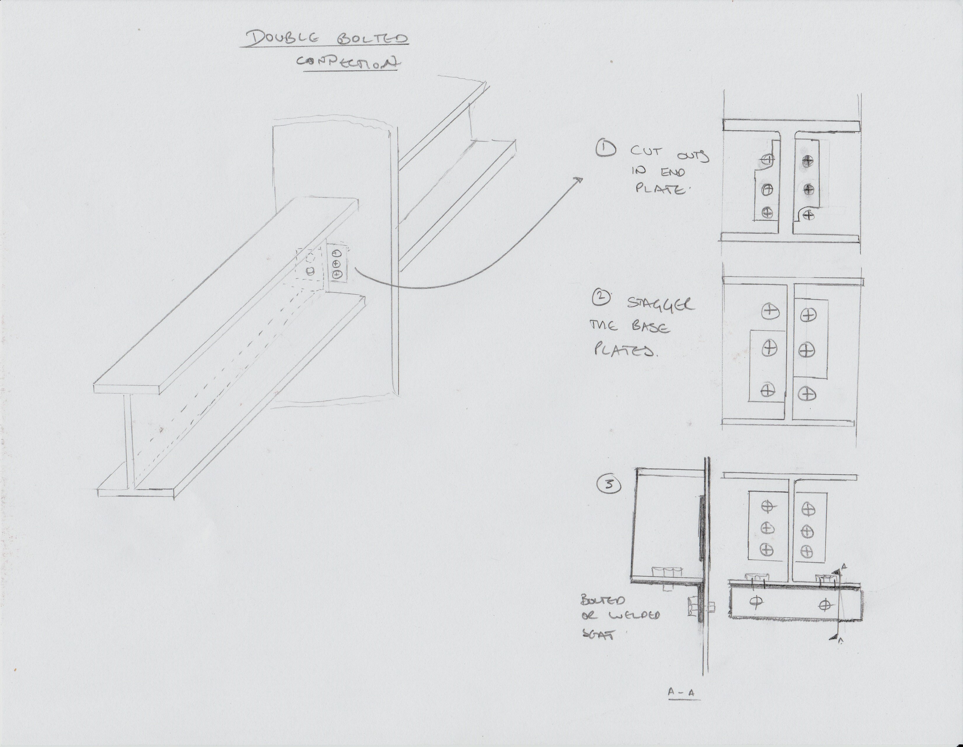
3 methods of fabricating for double connections
On site the majority of the shared connections are staggered (pic 2) to allow for this method of erection, however some have neither a cut out in the end plate or staggered base plates. When asked exactly how he had placed the beams the subbie admitted that he had removed the nut which had been placed after the first beam had been flown in and one of his lads had stuck his spud wrench through one of the other bolt holes. Highly naughty. We chatted about the situation for a while and figured that there must have been some sort of detailing error because it made no sense to not stagger the connection plates, and even less to not detail a factory fitted seat. Since he was the sub contractor I am not supposed to give him direction, unless it is an imminent safety issue, so I had to speak with my counterpart at the Principal Contractor in order to resolve the issue.
I went back to the office and was able to corner the resident steel expert who pointed me to the US American Welding Society document D1.1. This thrilling tome has within its many many pages a calculation for the strength of a fillet weld which is basically a function of the area of the weld and the grade of steel of the rod that is used during welding, with a factor of safety thrown in. I was able to assess from the field drawings what the heaviest beam would be in the whole construction and based my calculations on this. I proposed a 1” x ¼ “ fillet weld which could be applied in the field to the first beam that was flown in. This would be more than sufficient to hold the beam in place whilst the nut was removed in order to fly in the second beam. Obviously my proposal was only a recommendation and the actual design would need to come from the Principal Contractor. I highlighted this to them and requested that they submit an RFI for the field solution so that an audit trail would exist.
My proposal was questioned with an air of refusal by my counterpart who said that she had spoken to her manager who didn’t see the problem. A quick scan through the necessary paperwork, including EM385, the Specs and the Steel Erection Plan and a face to face with some relevant paragraphs printed out highlighted the government’s position. The issue remains unresolved as we wait for the RFI but the last I heard the Health and Safety guy had waded in and written a deficiency. This takes the issue in a more ‘formal’ direction which I had been trying to avoid.
Incidentally – I tried to find a similar clause in CDM but didn’t get on so well. Does anybody else know if there is one / where it is?
In other news – my wife and I went on a road trip to Niagara falls. Wetter than an otters pocket.

I also navigated one of the more arduous ‘trails’ in typical local attire fuelled by suitable amounts of coffee.

Standard US hiking Garb
Care Construction Challenge
On Saturday three members of the Lillie Square Project Team completed the 26.2 mile race in aid of the infrastructure development charity, there was an ex-Olympic swimmer, a fat bloke and me.
The 26.2 mile course included a canoe, bikes, a 10km run, loads of hills and stinging nettles. As we lined up on the start line it dawned on us that we might be out of our depth. The teams either side had brought their own expensive looking mountain bikes, looked extremely fit and were taking it all very seriously. We held our nerve, and each others hands, and when the command came we skipped off across the field in our dresses.

The bike was over, the run was still to come
There were many challenges along the way including a memory test, building a stable structure from straws and riding side saddle without falling off – although that last one was self imposed. Our high spirits and Haribo got us through and with the added encouragement that comes from being dressed like your Mum finished 8th overall. Most impressively we gained the highest points score from all the challenges and received the coveted “most brainy” award. Although clearly not the most brainy engraver given that the trophy says “most sporting” on it and the word “construction” is spelt wrong!
Victorious!
A great day was had by all and lots of money raised for a worthy cause. If you would like to donate you still can by visiting http://www.justgiving.com/lilliesavages
A video of the event can be found at https://youtu.be/wy-gCUoADiw
Site Two Fifty One – Dewatering while piling? and hot concrete.
Site Two Fifty One – Dewatering while piling?
“Draining the Bath”; this is our terminology for dewatering the site within the river terrace deposits now that the site is cut off from water recharge (secant pile wall bedding into London Clay). How soon is the question.
Considerations include plan area of site, depth of excavation, permeability, porosity and permissible discharge.
Various methods of how best to dewater have been discussed:
- Dig a hole to about 1m within the water table, insert a perforated pipe, insert sump pump within pipe and de-water. Repeat until required depth is reached.
- Drill out a core using the CFA auger and insert perforated pipe before the hole (wet gravels and sands) collapses.

View of site with pile rig roughly in the centre. When the excavation starts it will be from the far end of site and continue towards the near end (where photo is taken from). The second sump will be near the excavator bucket shown in the foreground.
I prefer option 1 because the sequenced lowering of the water table will reduce the risk of hole collapse because of not having to dig full depth in one go.
Some numbers. From the Ground Investigation the following figures have been assumed:
Initially dig depth: 5m, groundwater at surface of excavation, river terrace permeability: 1×10⁻³, porosity: 15%, plan area: 1900m2.
Putting this together gives 1500m3 of water which is to be removed using 2 sumps at either end of site.
The question is whether removing 1500m3 now, while piling is taking place is a good idea.

Image shows 2 sump locations. Sump 1 will be constructed by excavating down into the water, placing the pump and pumping until the ground water levels out. Repeat until 5m depth is reached.
Risk: Differential settlement. Removing 1500m3 of water is going to create (worst case) 15% more air voids which may settle up to 750mm. Clearly this assumes complete de-watering is achieved, when in reality there will be some moisture left within the pores. Additionally, the soil skeleton has strength and so despite the removal of water that does not directly imply the air voids will settle. If settlement does occur but happens evenly, then we could start dewatering now, but the risk is we don’t know.
Risk: Slip failure near to excavated area. Firstly the excavation edge will not be near to the piling operations. Secondly, by removing 5m depth of water will increase the effective stress by approximately 50kN/m2 – so dewatering will actually improve that risk.
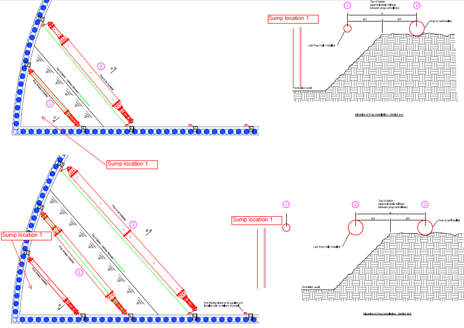
Method of excavation shown here in stages but sump 1 overlaid. Not risk of slip failure reduces as dewatering continues because of improved effective stress.
So what? Delaying dewatering until piling is complete will delay prop installation which delays excavation and the programme longer term.
Proposed solution to follow!
Hot weather and concrete.
Getting concrete in London is difficult at the best of times. However, this week a burst water main near Kennington has not helped, with delivery times exceeding 3-hours. With temperatures reaching into the forties, the concrete supplier has stated that tickets will have to be stamped meaning they cannot guarantee its quality! The concrete is for piles so the risk of quick curing is low once in the hole, the risk is getting it into the hole before it cures in the pipeline. This is not an issue I thought would be a problem in the UK, but turns out it is.

Burst pipe causes chaos.
The mix already has a plasticiser in it to make it workable for pumping and to enable cages to be plunged. To cope with the hot weather, the solution adopted was to add a retarder to delay the initial set. The retarder “slows down the initial reaction between cement and water by slowing down the growth of the hydration products”. The supplier, Lafarge Tarmac, does not have a plasticiser that works well in hot weather, hence the use of a retarder – it appeared to work well. The concrete did not cure in the pipes and the cages were plunged successfully.
