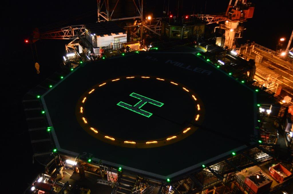
Miller Circle and ‘H’ Lighting
Some images of BP Miller in the North Sea with circle and ‘H’ lights installed.

US weather!!!
Whilst Pete and co. bask in Aussie sunshine, thought I’d post this picture taken in Buffalo (5hrs north of me) showing the impending snow storm advancing across Lake Erie!!!! It was 24degC last weekend, and dropped to -8degC last night…concreting cold weather plans coming to the fore!

What happened when I left for holiday
There were 3 main noteworthy occurrences when I was back in the UK for my 3 weeks of summer leave.
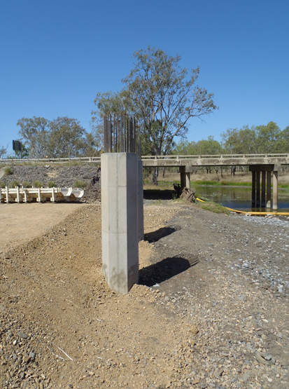
Pier 2
The columns on pier 2 were poured and the bracing was not installed correctly (as per the designers drawings). My site engineer had the drawings with the clear notes on them as to where the bracing should have been. However the leading hand convinced that it would be fine not to follow them and that it wouldn’t budge. This was not the case. One of the props holding the form in position failed and buckled during the pour. This was only noticed after the pour and no effort was made to try and fix this. The 2 columns needed to be poured on separate days (unlike the planned one day) as the 9m long vibrator got jammed in the reo at the start of the first column. There was no mechanical 9m hose to replace it, only an air vibrator (which has a larger diameter hose and head, meaning it is more likely to get jammed). The pour continued with this replacement and the damaged vibrator was cut off and left in place in the column. I say it was cut off, but what really happened was they hooked a crane up to the hose and tried to pull it out. That only succeeded in snapping the hose off. When I returned and saw the columns there was a noticeable slant in it. This was confirmed by the survey of the columns. The contract is very clear that the allowable tolerance for this type of element is +/- 25mm and at 57mm is well out.
I checked the formwork system and came up with a way to make it work, even though there was 65mm difference between the 2 columns. However it is up to the clients rep whether they will accept this. They are well within their rights to have the column demolished and redone correctly, however the rough estimate is that will cost around $100000 (all paid for by JHG). To make matters worse the first 3 spans of the bridge depend on span 2 being lifted in by 2 cranes sitting on either bank (one 350t and another 250t). So spans 1 and 3 can’t go in till span 2 is up. By not being able to pour pier 2 headstock the whole sequence is delayed. There is also the added pressure that the 350t crane is only available for a small window. Outside of this we will need to find another crane, which will cost much more to get on site. I made sure that the bracing on pier 1 columns was much more robust, it meant the pour was delayed by a day but both columns were well within tolerance so it was worth it in my opinion.
Broken pile
The piling rigs have now moved onto bridge 2 to start work, having crossed the Bruce highway during a night time road closure without incident. With the end of piling on bridge one this was a suitable time for a handover to another engineer who was initially only responsible for the bored piles and retaining wall. With everything handed over I was rather amused when on second pier of piles in bridge 2 they managed to snap a pile.
The clients rep blamed us, and we blamed unforeseen ground conditions. There was no-one from the clients team on site at the time, yet they are still claiming that the piling subcontractors “pulled the pile”. For those that don’t know the term, when driving a pile they can have a tendency to deviate from the vertical. In the early stages of driving some minor corrections can be made, but once a decent length of pile is in the ground any attempt to “pull the pile” into position can damage and even break the pile. To back up our case we have over 800 piles that have been installed as per our sequence without incident. I’d like to think that it was my steady hand on the tiller which stopped any piles breaking, however that is merely a happy coincidence. The next step is waiting for direction from the client. Any action prior to this could be a waste of time. Looking at things the way they are I see 3 possible options open:
1) Ignore it. Cut the pile off below the blinding level and don’t tie it into the cap. This requires the designers to go back and look at what support/resistance the pilecap as a whole needs to provide. All the other piles in the pier are well over capacity. The steelwork in the cap would likely need to be redesigned to ensure the forces are transferred away from the gap of the broken pile.
2) Use it as is. Use what capacity there is in the broken pile and tie the pile into the cap as though there was nothing wrong with it. This would also need the same checks as option 1, as the capacity of the broken pile would be unreliable over the lifespan of the bridge. In effect its just option 1 but not wanting to waste what has already been driven.
3) Drive another pile adjacent to the broken pile (towards the centre of the pier). This would be within the 3xD that the piles are currently spaced at, the steelwork would need to be redesigned in the pilecap and access to the position for the piling rig would be difficult (but not impossible). If the pile did break because of a large discontinuity then this pile may too also get damaged.
The Spaniard
Soon after my return there was a visit from “the Spaniard”. This is one of the executives from Groupo ACS who own Hochtief, Hochtief in turn own Leighton holdings, they then own John Holland. So lots of the executives from John Holland were on site to wander around. It was all to do with cashflow and why we were going over budget. His opinion/answer was that we needed to secure our revenue streams before acting on something. The example used was the large pile offcuts that we have on site. The additional cost for these offcuts should come from the client (in his opinion) as the piles are barely making it into the underdrive allowance. My simplistic understanding agrees with him. You would expect that most piles would be at the design toe depth, or that the average for the site as a whole would be close to the design toe (with some in the underdrive and some in the overdrive). However the vast majority of piles are sitting 3m above that design toe. My guess is that the designers were overly cautious in their design, and to reduce the risk of not reaching capacity, went for longer lengths of piles. By reducing the design risk they have created more work for the contractor, but at least there is plenty of capacity in the piles! The recent development that has come as a direct result of the claim for the pile offcuts is the direction from the clients rep that all piles must be driven to design toe. This is adding extra time to each pier, and could potentially damage the piles. The size of the hammer is such that were it used at full drop height the piles would likely split. The PDA gauges were connected after the split occurred to confirm it, and to give an indication of where the pile was damaged (roughly 3m below surface).
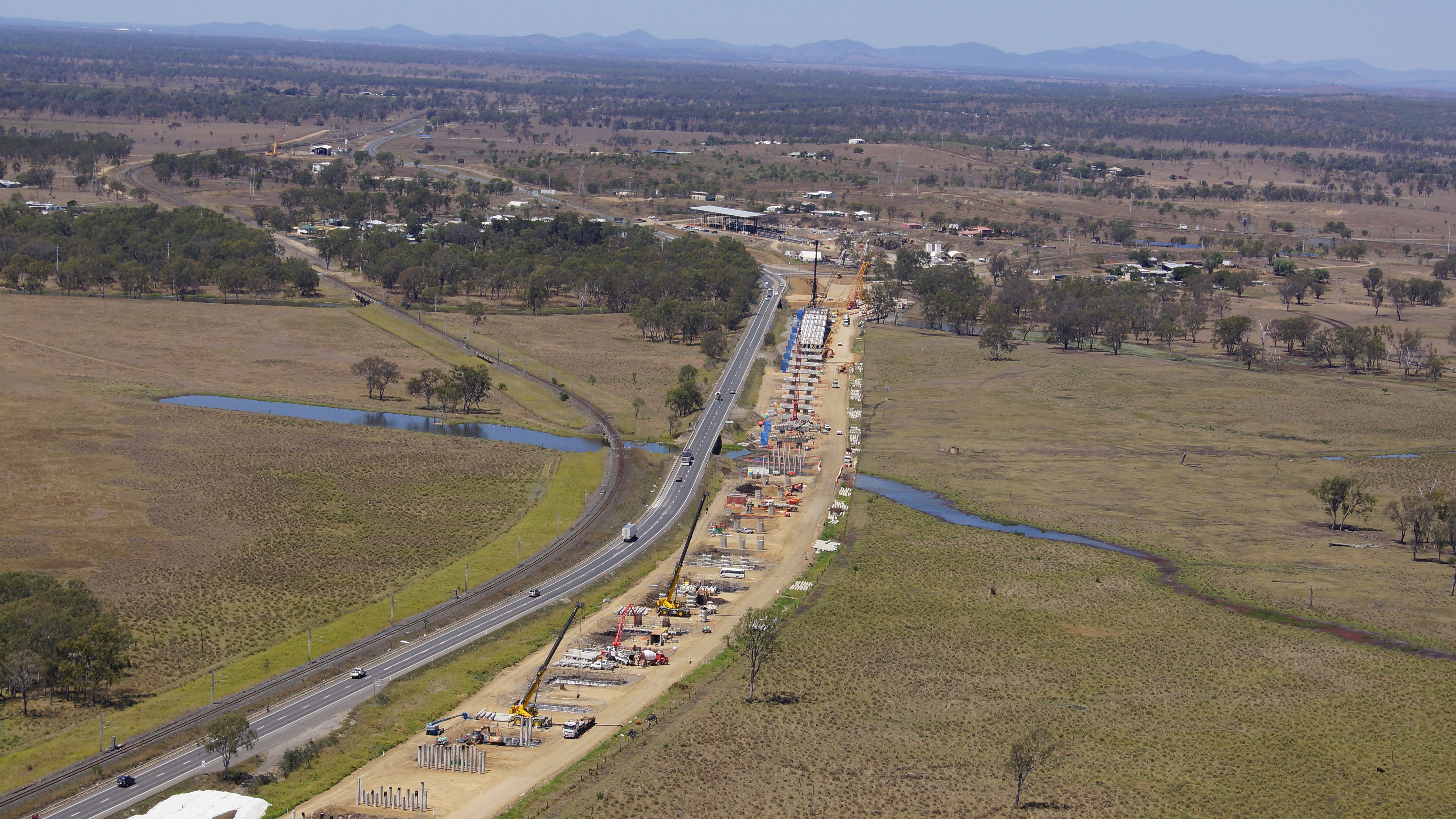
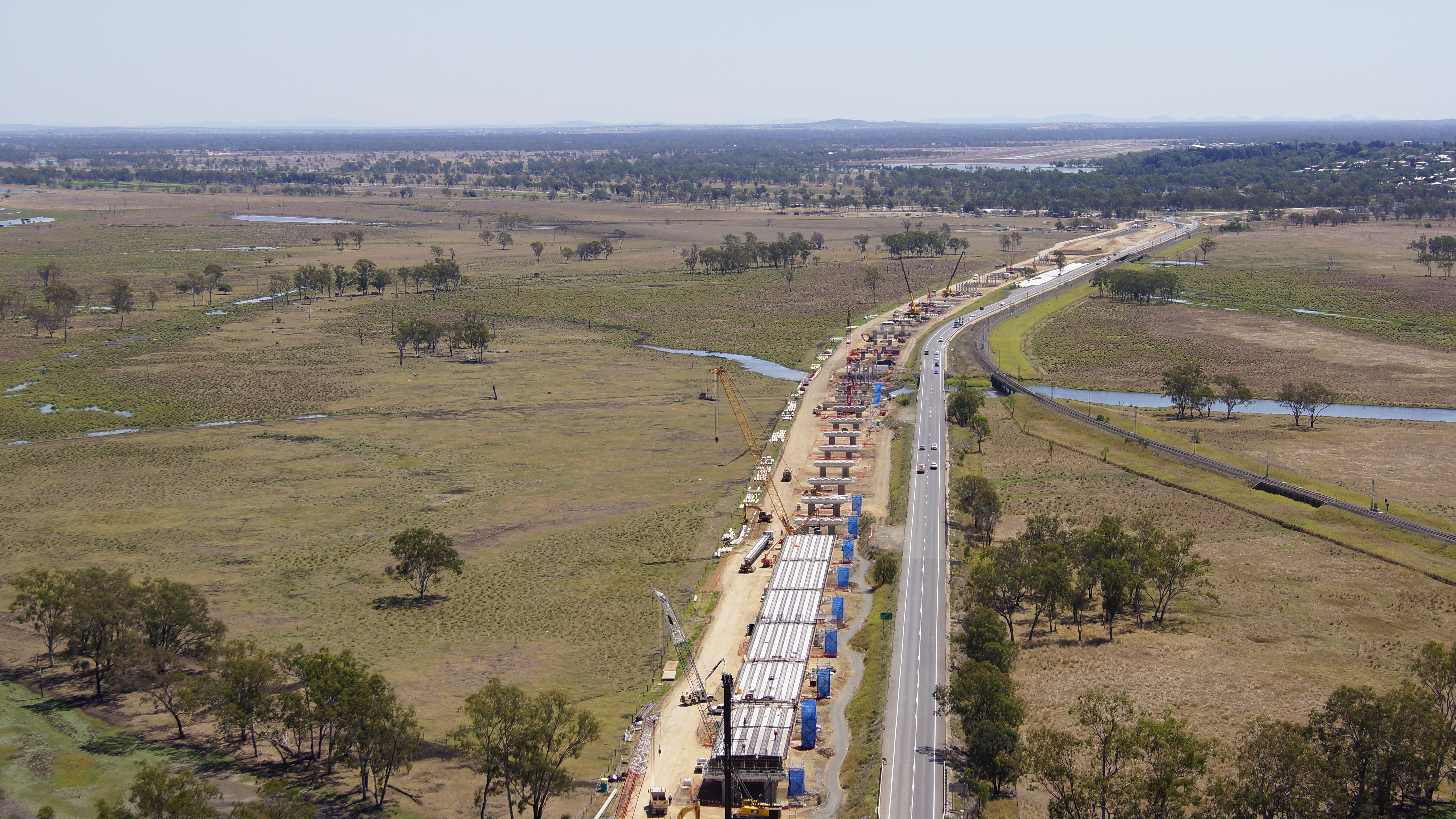
I’ve also got my hands on some aerial shots of site that were taken just before I went on leave. They’re worth waiting for the page to load to have a look at as the detail is pretty good.
Progress or Quality?
Having treated my self to a weeks ‘summer’ leave last week, I returned to what can only be described as widespread mayhem on the secodnary lining team. Three members of the team had left, including my line manager. Rats and sinking ships. I am still employed as a section engineer on the ‘binocular section’ of the crossover between the two running tunnels. The tunnel design and construction varies over its length dependent on function. For example, the running tunnels which maintain a uniform shape over a long distance, are driven by tunnel boring machine and lined with pre cast concrete panels for speed of drive. Enlargement works foR platform tunnels and concourses, including irregular shapes are ordinarily excavated and lined with steel fibre reinforced sprayed concrete. Uniquely, the binocular section uses a sprayed concrete primary lining, in composite with a cast in situ bar reinforced secondary lining. I will focus on this here. Binocular Section Function. In operation, the running tunnel will divide into two; the left hand side will form a crossover to the opposing running tunnel. The binocular sections are located in the areas noted EBX and WBX, at the point where the tunnel divides in two.The design is also shown in section, and is mirrored westbound and eastbound. 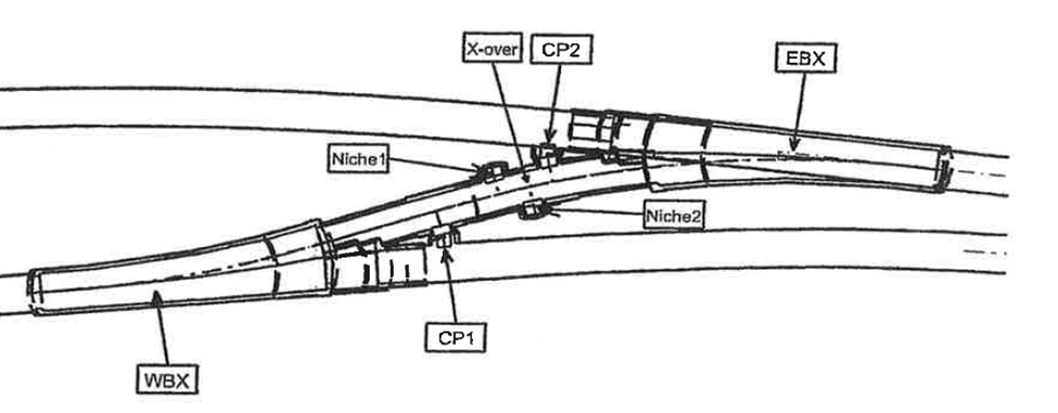
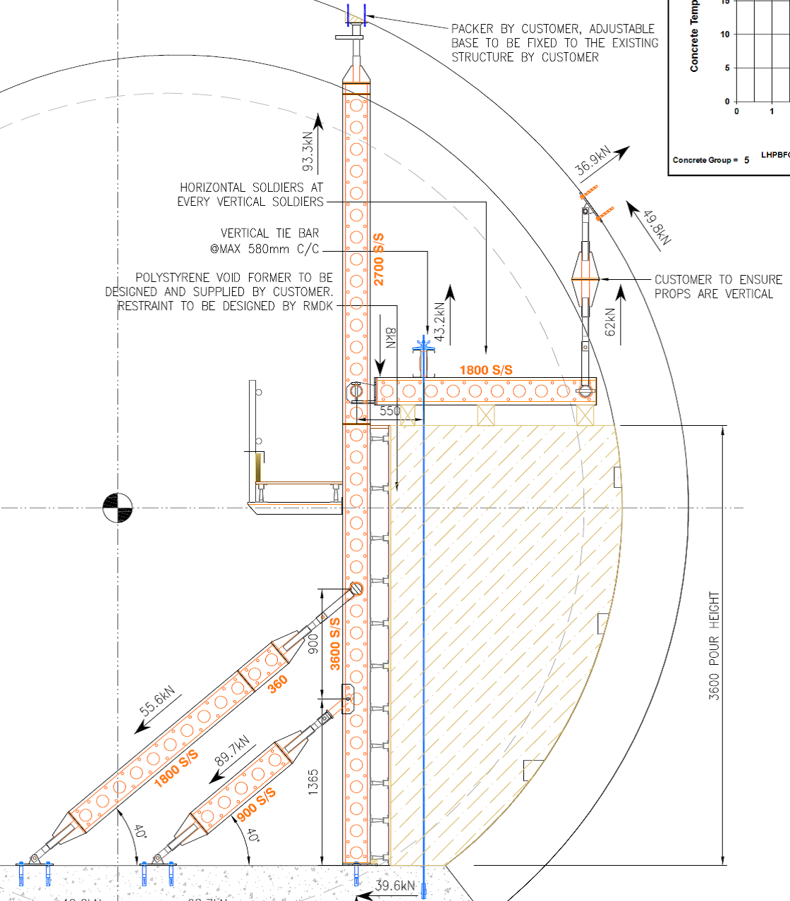
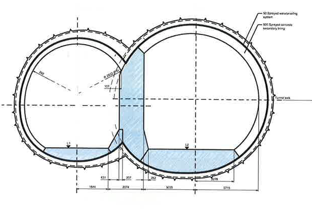 The internal profile, defined here by the bold line, designates the secondary lining, which is all cast in situ. Design. The front face of this section details a relatively large span at approximately 12.6m. This would be considered challenging to complete entirely in sprayed concrete. But the ‘figure of 8’ design creates high stress zones at the confluence of the two tunnels. This requires support which is designed in the form of the ‘binocular wall’ shown as the upright in blue. You will note that in comparision to the remainder of the secondary lining, the wall itself has large proportions. This design copes with the temporary state during the excavation of the second tunnel and prior to ring closure. Sidewall Issues. Aside from the day to day frictions that I will not cover here the casting of the invert, headwall and binocular wall sections passed largely without incident. However, the right hand sidewall was poured in my absence, with some issues. The profile of the sidewall is formed by the use of bespoke poystyrene void formers, which are designed and laser cut by a specialist contractor. They are supported by RMD Kwikiform temporary works, again designed by sub contractor. Despite being contracted out, temporary works repsonsibility falls to us, so I got involved here to check design calcs, and made some adjustments for buildability purposes. Designs are shown below
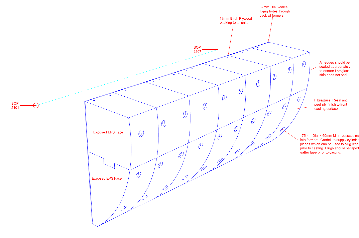
 You will note that the profile presents a tricky detail for the pouring and vibration of concrete at the lowest point, particularly given the congested steeelwork incorporated here. Way ahead of this pour, I sought to preempt this issue by designing, in conjunction with the supplier, a self compacting mix, which I trialled and had approved. This was supposed to replace the existing mix, which was also susceptible to entrapping air due to the type of polyfibre it contained. (See previous blog about mix designing – a delight). Thus I went on holiday happy that I had forecast a design risk, conducted some analysis, came up with a solution and communicated it effectively. (See John, I was listening…) I returned to this….
  The poor resolution on this phot doesnt give you the full joy of this. You may note pock marking across the bottom 2/3 of the wall. This is caused by a proliferation of air bubbles trapped in the lower section, exacerbated by poor vibrations. As it turns out, the old mix was used despite my amended activity plan explicitly stating the new mix to be used. The entrapping of air is quite obvious here. I suspect, if the wall was cored, that the mix would have a relatively low density, and may fail on compressive strength as a consequence. You will also note the cold joint which runs the length of the wall. Apparently, pre planned road closures causing traffic in London, delayed the follow on wagons by approximately 4 hours between pours. With no engineer on site when it finally arrived, the site foreman continued the pour based on ‘whether we can still get a poker in the mix’. Conclusions The loading path in this section of wall puts the wall predominantly in compression. That said, there are performance requirements pertaining to flexural strength. Assuming there are no major voids at the cold joint, this should not present an immediate structural problem. My concern is the threat of water intrusion and consequent acid attack in the high sulphate environment of our local ground, over a 120year design life. However, it is likely that these concerns remain on the aesthetic rather than the structural in this instance. The air entrainment is a bigger concern. Although the contractor kindly offered to patch repair the surface to bring it in line with the clients specified surface finishes, I feel like they are missing the engineering risk. I demonstrated the effect on compressive strength that a lover volume can have in my failed mix design trials, and I suspect in we were to core this, we may find voids and poor encapsulation of the rebar, along with a low compressive strength. The client has yet to request this but Im certain it will. I find it hard not to be deeply frustrated and cynical about all this. All of these issues were foreseen and planned for, but coherent planning of a task from start to finish is simply not in the culture here. A single responsible person for these task s is not easily identifiable and noone is held to account. A common theme throughout my attachment here is that progress always trumps quality, and even cost. These problems were caused by not following the instructions, and a lack of engineering oversight, combined with a rigid application of quality, through the inspection and test plan that I wrote to govern this. The rush to complete, and consequent mistakes made have achieved a delayed program, and extensive rework. We are under an NEC (C) Target Cost contract, so as long as we raise this issue through a Non Compliance Report, the ‘pain’ is shared with the client. So incompetance on our behalf of the contractor has led directly to waste of public money…not only frustrating, but actually quite immoral. In other news, I’ve found something as uncomfortable, as a John Moran Q&A. Tough Mudders Electric Shock therapy
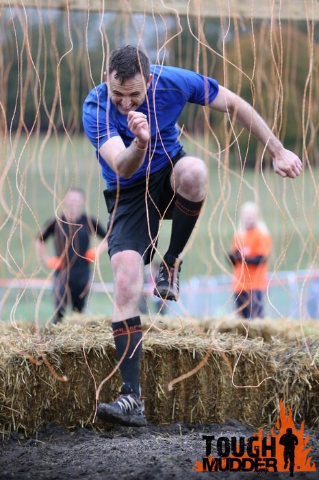
Something for Joe since I sent him to sleep with my last blog!!! The Worlds Biggest Crane
The article below was taken from the Mace news page, and again I thought it was quite interesting!! I’m hoping I don’t miss the mark again Joe! Nothing like a bit of crane ‘appreciation’ top trumps!!!
How to build the world’s largest crane
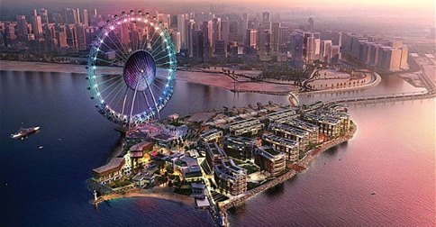
Faced with building the biggest observation wheel in the world, the Dubai-I team is no stranger to challenges or to beating records. And this month was no exception with the delivery and erection of the Mammoet Platform, Twin ring Containerised (PTC) 200DS, the world’s biggest crane.
The PTC 200DS was designed and built by Mammoet in Holland and has spent the last two years in Texas working at an offshore oil assembly depot lifting a 120m spar as part of a deep sea drilling platform. It was disassembled in April 2014 returned to Holland, cleaned, maintained and thoroughly inspected prior to travelling the 6000 plus nautical miles to the UAE Port of Jebel Ali.
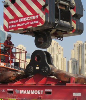
To transport the huge crane the 221 containers had to be offloaded and then placed onto articulated vehicles where they were then transported by road to the Bluewaters Island site in Dubai. They were then offloaded by one of the three crawler cranes and laid out in order of erection sequence by the site based team of trained Mammoet erection specialists. The crane is so large that the operation required one LR1600 crawler crane @ 600Te capacity, two No 250 tonne and one 180 tonne crawler crane sited in the unloading and distribution area.
During the erection there have been several critical lifts, in some instances three of the four crawler cranes were used to carry out a single lift. The critical lifts have been impressive and professionally executed by the Mammoet erection team. The most demanding of these was the lifting of the back mast from horizontal to 70 metres with all cranes travelling 60 metres in unison whilst lifting a load of 340Te.
Senior Project Manager Piers Sidey said: “The fact that this will be the largest observation wheel in the world by some margin presents huge challenges on several fronts. The designers are pushing the boundaries to find effective and economic solutions. When you double in height the forces, stresses and deflections are magnified many more times. Secondly since we need to maximise off-site assembly as far as possible the wheel will be delivered in very large pre-assembled sections up to 118 metres long and 1800 tonnes in weight. Hence the need for one of the biggest cranes in the world.”
The Mammoet PTC in numbers:
221 containers required to transport PTC200DS
3,400 tonne lifting capacity
830 tonne – weight of Dubai-I leg
1,800 tonne – weight of Dubai-I spindle and hub which will be single lift at over 100m high
123 metres – length of boom
55 metres – length of jib
182 metres – total height at tip of jib
87 Te – weight of hook block
123 metres and 415 tonne – heaviest lift during construction by three cranes
Here is a pdf with some more info of the process of DubaiI crane process.
Temporary Works and EuroCodes
I noticed an interesting article in the NCE mag this week (kind of rare I know!) about the relevance of EuroCodes to Temporary Works design and the use of the term ‘Safe Working Load’ (SWLs).
The key issue the author brings up is how do you use a prop with a ‘Safe Working Load’ in a EuroCode compliant design? Was the prop originally designed to EuroCode? Is it ok to assume the ULS capacity is 1.5 times the manufacturers stated SWL?
Having done a few temporary works designs now using just SWL (with no factors at all), as well as with ‘old BS’ verification and new EuroCode verification it certainly is a bit of a muddle. Proprietary equipment specifications can have a myriad of terms which can be confusing, so sticking with Safe Working Loads in my view is essential.
Has anyone come across this problem???
Danville can sleep safely!
The ‘wall’ is now complete…inspected, handed over, warranties issued and snag list complete. The only outstanding issues I still have to deal with are working through the red-line drawings, chasing up failed submittals and rebutting some anticipated REAs. A good sense of accomplishment, particularly having finished a month ahead of schedule so smiles all round. Looking at it now, one could never imagine how much toil went into a relatively simple and small structure…but one that is key to saving life, and sustaining a major transport route through Pennsylvania. I compare this (on a far smaller scale) to a similar feeling probably felt by engineers involved in the Dawlish SW train track repair – a mammoth task which at the end looked pretty undramatic, but was neverthless paramount to both safety and sustaining transportation routes, tourism, economy etc etc.
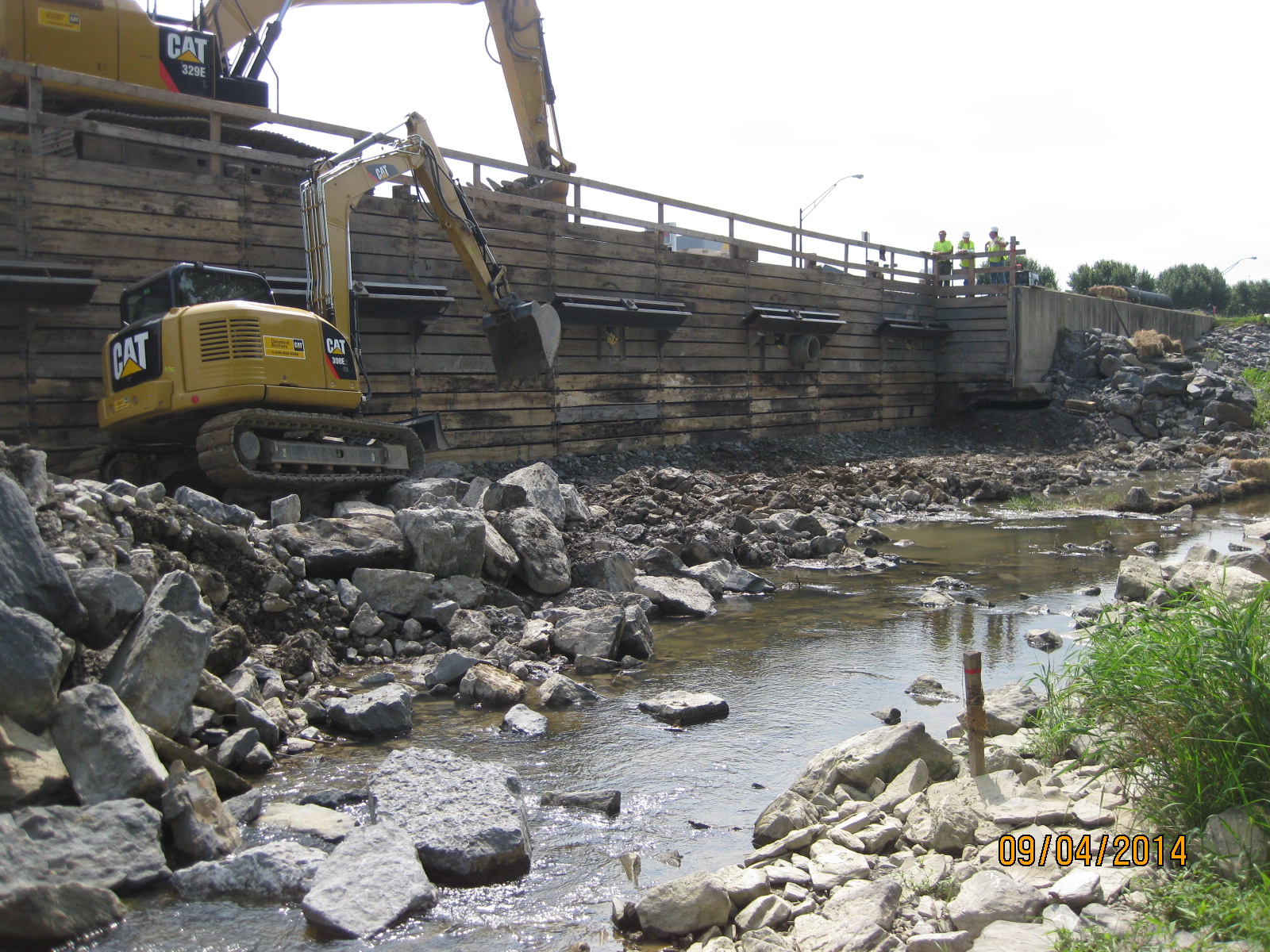
Excavation and shoring system – 2 months prior to completion
Inspection and hand-over
I have now switched the majority of my focus to the on-base warehouse project; I’ve been really impressed by the management, work ethos and professionalism of the contractor on this site – one of the advantages of the USACE posting is being able to observe and contrast management styles across different projects, but also to gain knowledge from a large pool of contractors. My focus comes at a time of large internal slab-on-grade pours incorporating underfloor heating systems; the base has suffered in previous projects from concrete curling issues so I’ve spent a lot of time digging through codes, specs, technical reports, and working closely with the QC manager to ensure that the mix design, conditions, and handling eliminates this problem…so far so good on floor flatness tests. Temps are due to drop down to 0degC next week; consequently we have been working through a cold weather plan to ensure everything continues on track – some of the research behind TMR1 has proven its worth!

The highlight of this week was the testing of rescue procedures of a man-down on the roof! Clearly the on-barracks fire brigade were warned off, because the whole wild-west turned up on-site within 2 minutes. Despite my muffled laughter of handle bar moustaches (this wasn’t Mo-vember!)and denim jackets, the serial proved valuable in testing the procedures…or lack of! Following a debrief, I essentially rewrote the entire actions-on procedure for the contractor who, to be fair, didn’t really have a starting block – for once, some practical non-engineering military knowledge brought to the fore.
When Mark grows up he should become a valve doctor
I went to a very interesting seminar on valves used in the oil and gas industry for high severity operations.
It concentrated on compressor recycle lines and flow line choke valves.
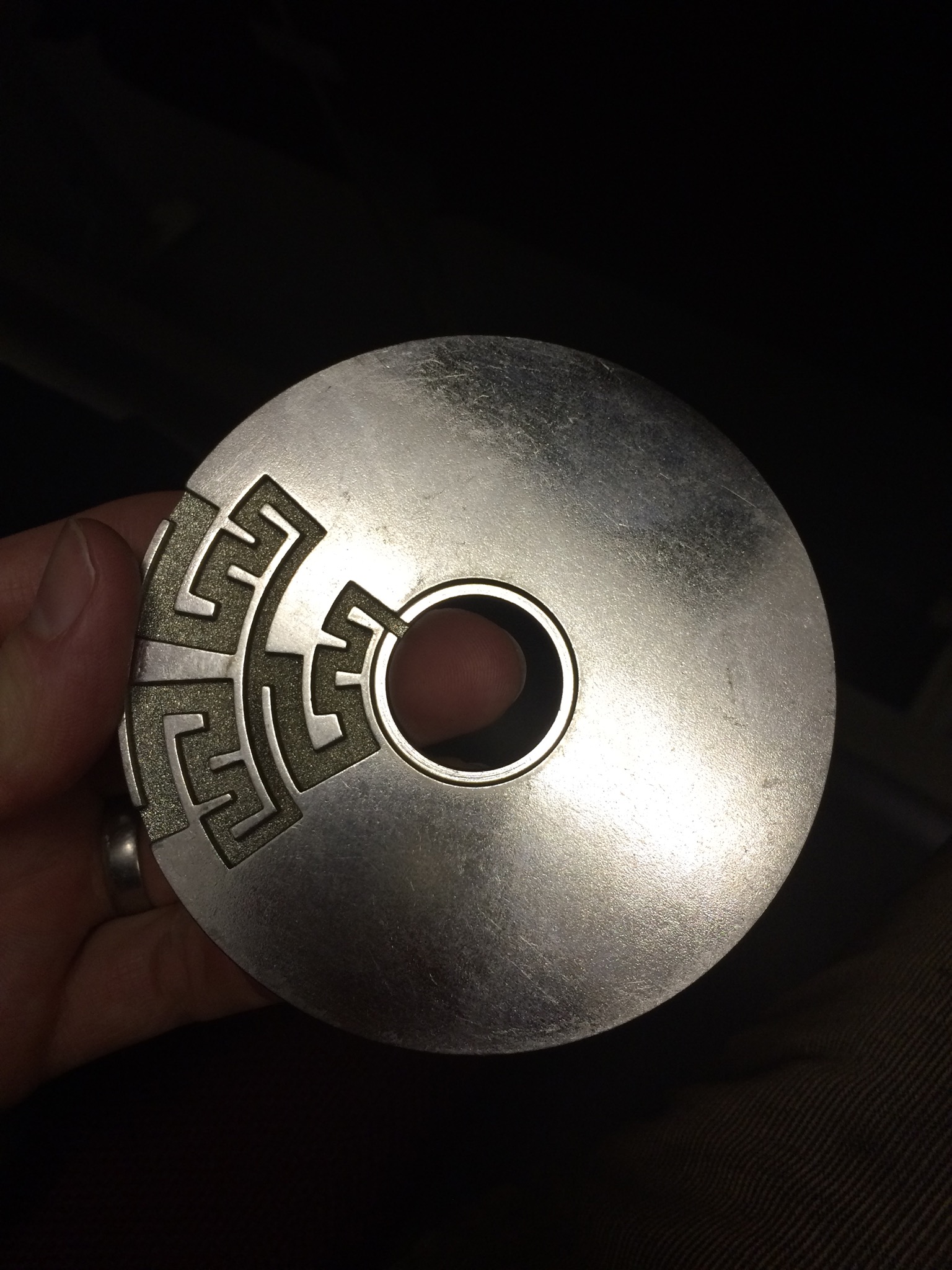
The subject matter covered included material selection, how to control flow rate, pressure differential, corrosion and erosion resistance, analysis of modes of failure and of course developing technologies. They use DRAG technology, which is essentially using a tungsten carbide filter to surround the valve plug on a globe valve in liquid stream to protect the plug from damage, excessive pressure drops and to remove any chance of cavitation. A picture of one of the discs that together with lots of other discs stacked together form the filter. The flow being from outside to in.
Surprisingly, it was not delivered as a sales pitch despite coming from a private company. I think that they know what they produce speaks for itself. I for one learned a huge amount and will be applying some of the lessons learned to my projects. It will be a way of ticking the new technology competency.
Mark, if PEW doesn’t work out you should consider it…
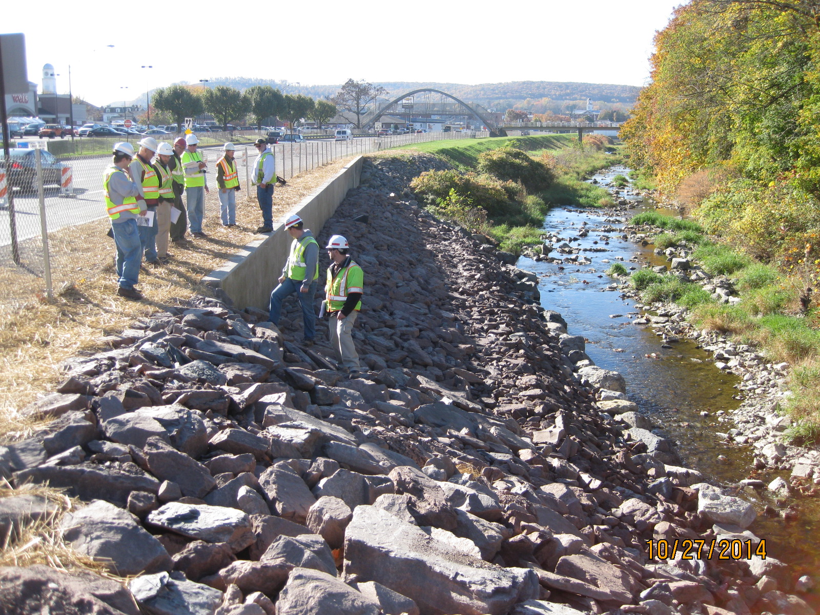
Topped out Aerial shots.
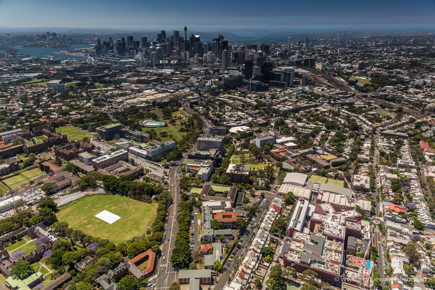
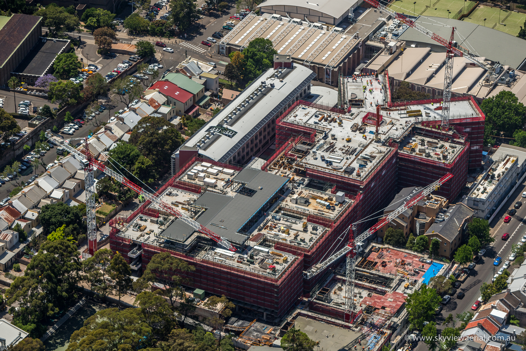
The work site is in the bottom right corner
Back to Blog.
Noting that it’s been a while since i blogged. I intend to use a number of blogs to comment on what I’ve been doing, using this first one as a general comment on the project progress before highlighting specific engineering issues in the next couple.
This week has seen some significant milestones for the Abercrombie business school, allowing opportunity to reflect on a number of issues.
1. Main Structure Topping Out.
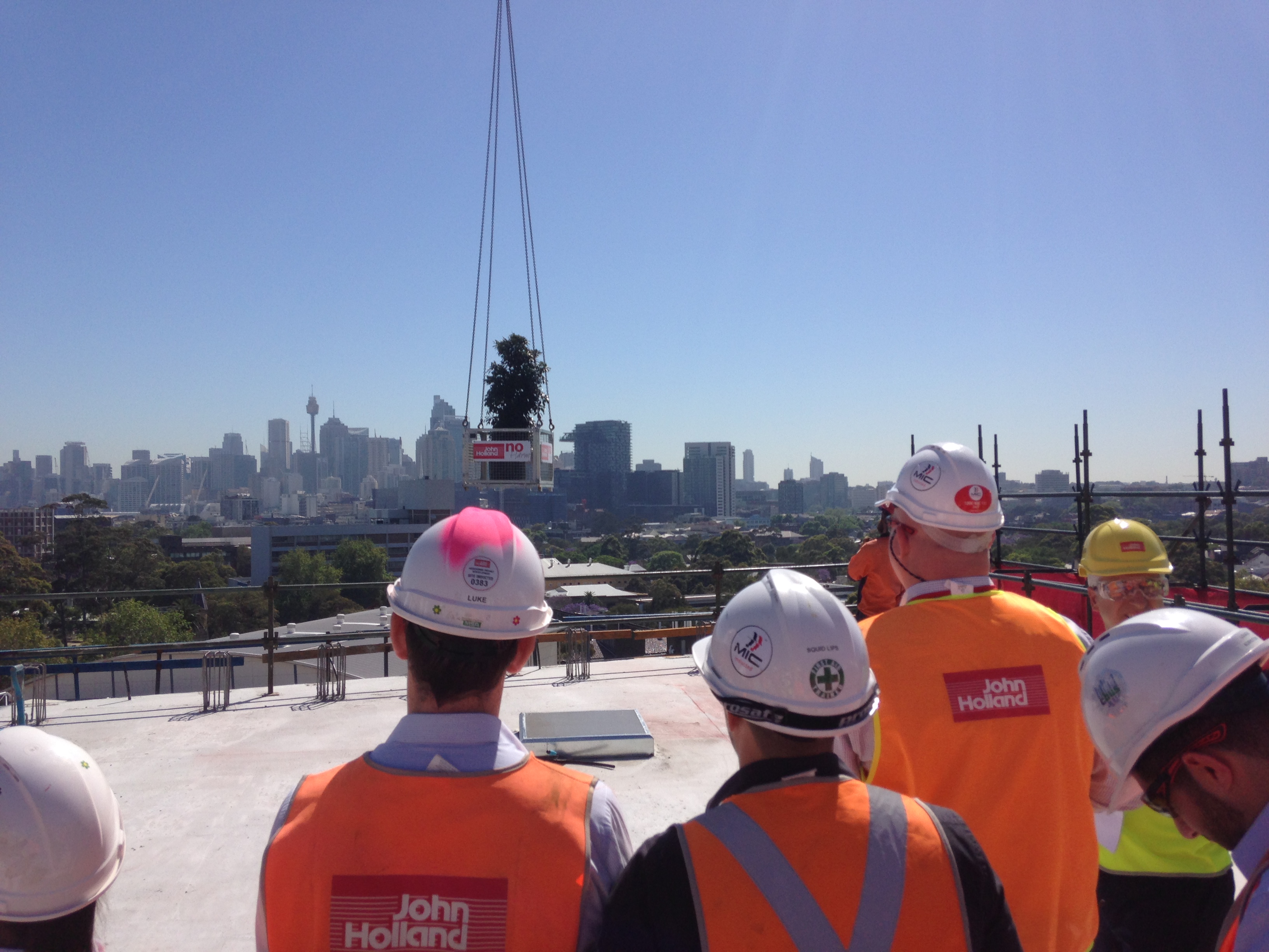
After many months of blood sweat and tears the final concrete pour for main structure of the Abercrombie Business school occurred last wednesday, with a topping out ceremony on Friday Morning, with guests and dignitaries from the university, John Holland and the Army of consultants and architects employed on the job. with a floor plan of 7000 square metres, 6 floors above ground and 3 basement floors and considering the partial deck collapse experienced earlier this year, as well as inclement weather and this has been no small achievement considering the first on ground slab was poured on 17th December last year. That having been said, the project is no running approximately 4-5 months behind schedule.
From a services perspective topping out is excellent news, Largely due to the fact attention and focus for resources will now switch fire to fit out, with access available to all floors expected in a week or so, following the full stress of the top deck and formwork stripping below.
2. HV Substation Structure Handover to Ausgrid (National Grid)
From a services perspective, achieving handover of the HV substation structure to Ausgrid to begin HV fit out has been a personal and services team victory. With superstructure of the business school running so far behind schedule a deal was struck between clients and John Holland team, that if the structure could be finished by the end of September all LDs could be waived. As a result all formwork and concreting resources had been focussed somewhat myopically on structure (and still not achieving the september deadline – LDs are now in negotiation) , whereas the actual Critical path of the project ran through the substation ‘Power On’ date, in order to achieve commissioning timelines and meet the new extended deadline. Similarly getting the project team to understand that pushing the completion of internal elements of the structure such as Main switch rooms and comms rooms will ultimately cut large chunks of time out of the overall program, allowing staggered handover of comms rooms to the university for their own fit out teams to commission, significantly reducing the deadline to commissioning.
The Internals of the new business school HV substation prior to handover
 Main LV switch room
 Main Comms room
3. Variety of project involvement.
While admittedly the bulk of activity has been focussed on structure, that does not mean to say that throughout the bowels of the building Services have not been busy. The scale of the Abercrombie business School project has meant that I have received what I feel is good exposure to a whole range of disciplines Including but not limited to coordinating all the Mechanical, Hydraulic, drainage, stormwater and sanitation, as well as heavy involvement in Electrical, including various H&S policies and Method statements. I have been running the services subcontractors meeting and assessing progress claims for sub contractors, as well as acting as the main services point of contact for construction related issues as well as services related QA and defecting. Fortunately for me, culturally, the project team here have been welcoming, as early on in the job a long serving but relatively junior services engineer left the job, allowing me to step into his role.By my calculation, with accommodation costs taken into account I represent a $150000 annual saving to the project on salary alone.
That having been said, as I’m sure Ben and Ollie have found, early negotiations with the project director over working hours, accommodation costs etc, had to be handled delicately as there is really no passage of information between JH head office and the projects as to what to expect from a PET student. The benefits to this is that following early frustrations you can carve out a direction for yourself. An early interest in BIM has meant hat I have ended up largely taking on delivery of a ‘BIM 360’ solution – BIM Models downloaded to Ipads to allow remote access on site, for defecting and as builting the BIM model, and last week I spent two days with our BIM consultant learning how to assemble the overall design model from the subcontractors designs, publish, clash detect and issue direction to the designers for completion of the 3D design, with a view to me taking on responsibilities for the completion of BIM Coordination for the last few turns of the handle. My line manager seems to be as focussed on my development as contributing to the project, and as a result has arranged for me to shadow the commercial team for a few days later in the month.
Now i have returned to the Blog, my next post will focus on some of the actual engineering issues that I have encountered however I will finish this one by just commenting on how Impressed I was at the breadth of disciplines encountered during phase 1 I have actually received exposure to so far, including the civil and project management aspects. A shortcoming would be Comms equipment and infrastructure, Understanding that in our world the technicalities of such systems will be handled by the Corps Signals, but with the volume of IT systems likely to be encountered a working knowledge of IT infrastructure may be of some use, at the expense of the depth of detail of others disciplines.
