And now for my next project……
Like my colleagues, the blog has been on hold whilst I finish my thesis. Since then it has been hi tempo in the office too, as we complete (mostly) the Marine Terminal HVAC design and start on a UAV hangar design in upstate New York. As rather a lot has happened in the last few weeks I shall try and make this bite size.
Quantico: My invitation from the USMC meant I was able to sit in on a 1 star R&D briefing on the latest energy saving measures to be implemented. This included not only changes in policy but a whole host of kit that can either harvest or generate energy to supplement current needs. This includes boots that can charge your radio batteries as well using waste generator heat to wam up shower water. A very ineresting experience particularly as the USMC seems to have less money than we do and is getting industry to do the research for them rather than doing it themselves for the sake of those lucrative government contracts. Needless to say some of this experience ended up in my thesis.
Caven Point: As with all design project coming to an end, this has been a period of mind changing and total redesign. This including swapping ouot VRF for VAV systems, totally removing VRF from workshop areas and changing all the asociated air handlers, make up air units, louvres, fans etc accordingly. Then at the 90% we received requests for additional items including, extra partition walls in large office areas (total recalculation for the room(s) and equipment resizing), changing A/C to just ventilation in three warehouse rooms (more equipment redesign), Air Curtains over all roller doors (to stop flies and heat loss – a ‘helpful suggestion’ to the end user from one of my team) and all this with a week to do just after the thesis deadline. The lack of communication between the design team has beenthe biggest frustration in this period. It still happened that every day I log on and there is a change on the drawing that affects me considerably or the user has realised that something is not quite as they remember asking for and needs changing. Part of the game I know but the inability to stick to the design requirements set out at the beginning of the project has added delays. The whole process is so rushed that any Contractor taking this on stands to make a fortune in changes due to design issues. At least I won’t be around when that happens……..
Fort Belvoir VCC: I attended the project kick off meeting in early April which turned out to be a classic case of ‘You can lead a horse to water…’ with some of the shareholders. To recap, this is a visitors control centre which processes people attending mostly retirement functions who are not DoD employees. A glorified guard room in short. However this facility must also be a 24hr facility, blast protected and strategically placed, just in case the worst ahppens. Located after the turn in to base but before the main gate, it is still a design that needs refining hence the meeting. What started off as formality eventually ended in a 3 hour contradictory argument. But to explain this I need pictures:
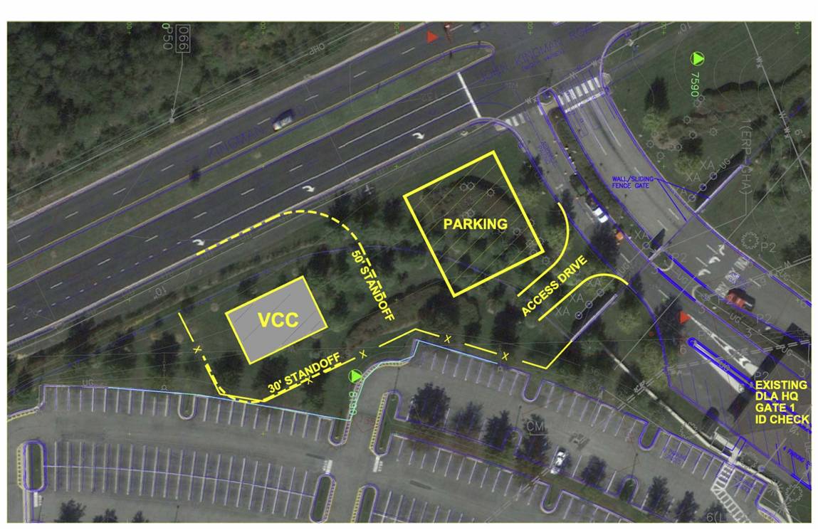
Option 1 the Garrison Teams favourite optioin
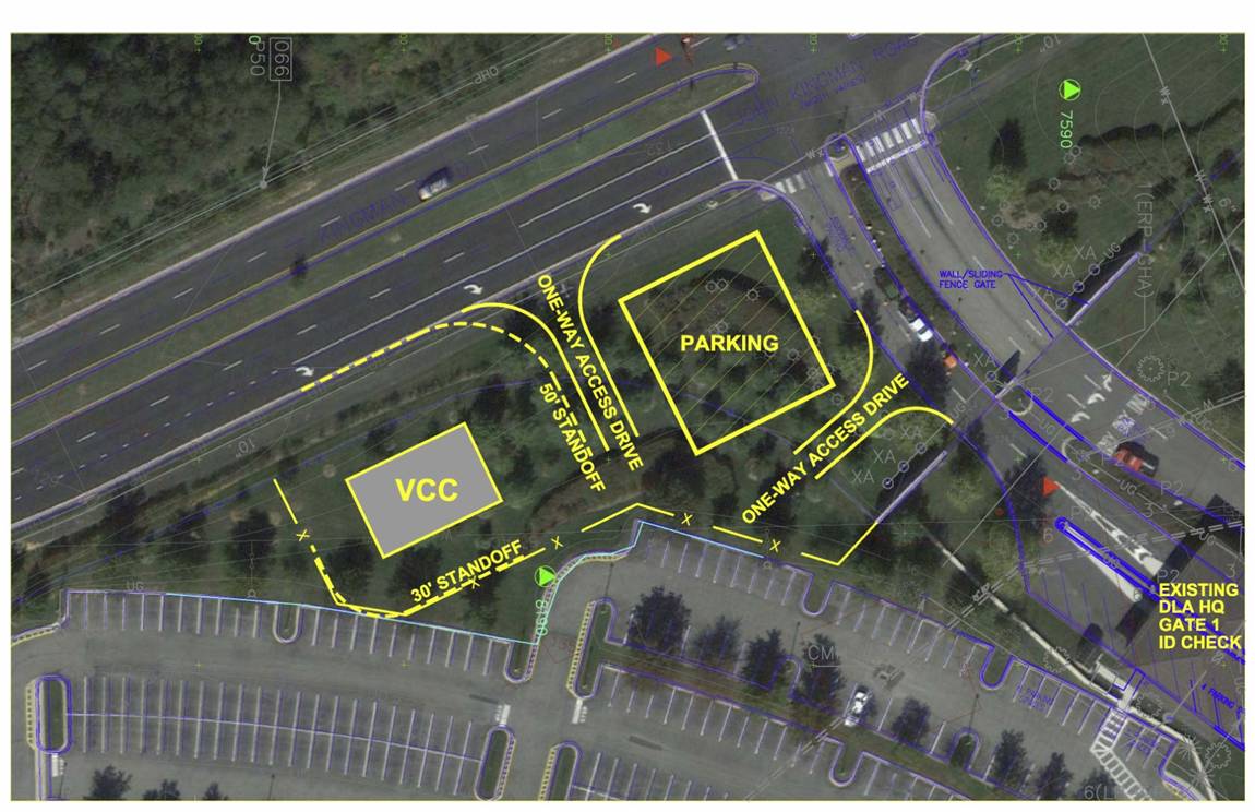
Option 2 Everyone elses favourite
From the start the Garrison maintenance team said option 1 was the only choice. We questioned this because it clearly interferes with traffic going in to the main gate, causing a potential bottleneck which stop entry to the post or could easily be missed in which case the only way to get back to it is to go on to camp, turn around and go back on the highway. We were politely told this would not happen because the only people using this facility were going to be going to retirement parties normally held mid morning, coming infrequently and that people turning around behind the gate is just what happens (I should add that this is the most heavily guarded gate I have seen in the US!). When we pointed out option 2 offered a far less likely chance of causing obstruction because it could be accessed off the main highway and if we made this road 2 way and no one would ever need to go through the gate in order to turn round, thus improving security. We were told that this choice would obstruct the rush hour traffic on the highway because up to 100 people could need passes all at the same time, any time of day (probably rush hour) and that the gate guards were quite happy waving people through to turn round! There was still no resolution after 3 hours so it was left to an admiral to make the call. I think he diplomatically chose a design that was a compromise. From the mechanical point of view, one of the staff was keen to get renewable energy in to the building. They wanted solar water heating and a geothermal heat pump. We presented the case that solar water heating was not financially viable for a single toilet sink and that a geothermal heat pump would be $40,000 more than air source heat pump and would take over 30 years to pay back. The customer went away unconvinced that money should be a barrier to green technology!
Fort Drum UAV hangar: Because the VCC was so small I was given the chance to put my radiant floor heating research to the test with my next project. This is $30 million UAV hangar in Northern New York State where the minimum temperature is around -30 degrees and 35 degrees in the summer. Most of the building is a standard design but the loads for the location need to be recalculated. However the hangar floor (25,000 sq ft) is going to require full underfloor radiant heating and no one in my department has any experience so I get first go! We have no design software for this so it is back to hand calcs to work out all the losses etc for sizing. Still no idea how I will draw this system either. And a 65% design is due in 2 weeks!

A UAV hangar
OPD: In the USACE Officer Professional Development course we are given the chance to get an insight in to the responsibilites of the District from the eyes of the Commander which means seeing some pretty interesting stuff in the local area. We started with an American PFT complete with 2 mile run, which we all passed, before heading off to the debris vessels. These are used to keep the water ways clear of logs and other debris as well s scooping the bodies out when aircraft land in the Potomac. Next was the Springfield site where a specialist team was clearing mustard gas and UXO from a former university house basement using equipment that would not look aout of place at USAMRICD. This required great tact from the team in dealing with the public who are understandably twitchy about having UXO in theback yard! We visited the Washington Aquaduct to see how USACE produces most of the water for the DC area before a visit to the new Intelligence Community Campus Building. The current buildings are being ripped out, including the fascade, then are being rebuilt as lecture facilites to meet modern code as they were nearly all built in the 50’s and 60’s. This propject had encountered numerous problems with the public, who did not want to see any new building and were against all construction (even if it is in the National interest). This resulted in delays and a reduction in height of the multi storey carpark so that it is below tree top height. Our next day started with a VIP trip to the Pentagon. This building is absolutely enormous (2.4 times the floor space of the Empire State Building) and was modernised recently to be a little town with every single type of shop so no one ever needs to leave. We were given a brief on the role USACE plays in the DoD and then saw the site of the 9/11 impact where a Chapel of Reflection commemorating those who died, is located. After a hasty lunch we tool the metro to the Capitol Building where were given a guided tour which included showing us the few areas the British did not burn down in the War of 1812. We are able to see the Senate debating but this was not that exciting with only 2 senators in the chamber. The final part of the experience was a trip to Arlington National Cemetary which is managed by USACE too and is still Army property. The plot size is enormous and they are having to expand to meet the projected demand until 2050 (barring no more major wars obviously). The most impressive part was seeing the guard change at the Tomb of the Unknown soldier. If you think you can do rifle drill, google this and find out how it should be done!
And in other news:
The weather has been a little unpredictable recently, with a retaining wall collapsing that took half a street with it in central Baltimore. The rivers rose 6ft in 12 hours and we are getting the same again tonight. Wildfire season has started in California which only mention because the USMC base I was invited to in order to see the demo of the equipment mentioned at the briefing has just been evacuated!
I was able to volunteer for a STEM evening at a local Elementary school where the kids learned how to build bridges using toothpicks and marshmallows. This was optional for the kids but amazingly we had 3 full classes and a merry time was had by all.

And on the home front Warrick is really enjoying baseball and develping a good swing, Ava has now turned 4 and we are making the most of the last few months by day tripping to New York, Philadelphia and Amish country with a break in Ocean City due in 2 weeks. So much to do so little time……
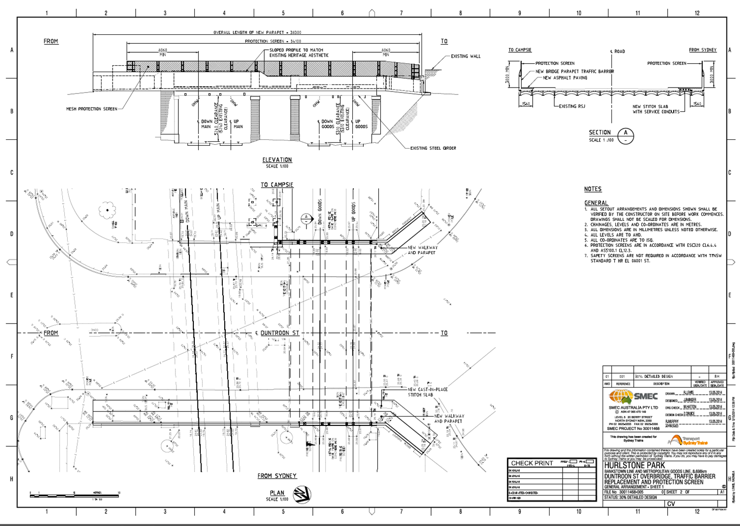
Bridge Parapet Traffic Barrier Design
It has been a while since my last offering but now that my thesis is in and forgotten for the time being and I have finally started my CPR reports here is an update on life in the design office.
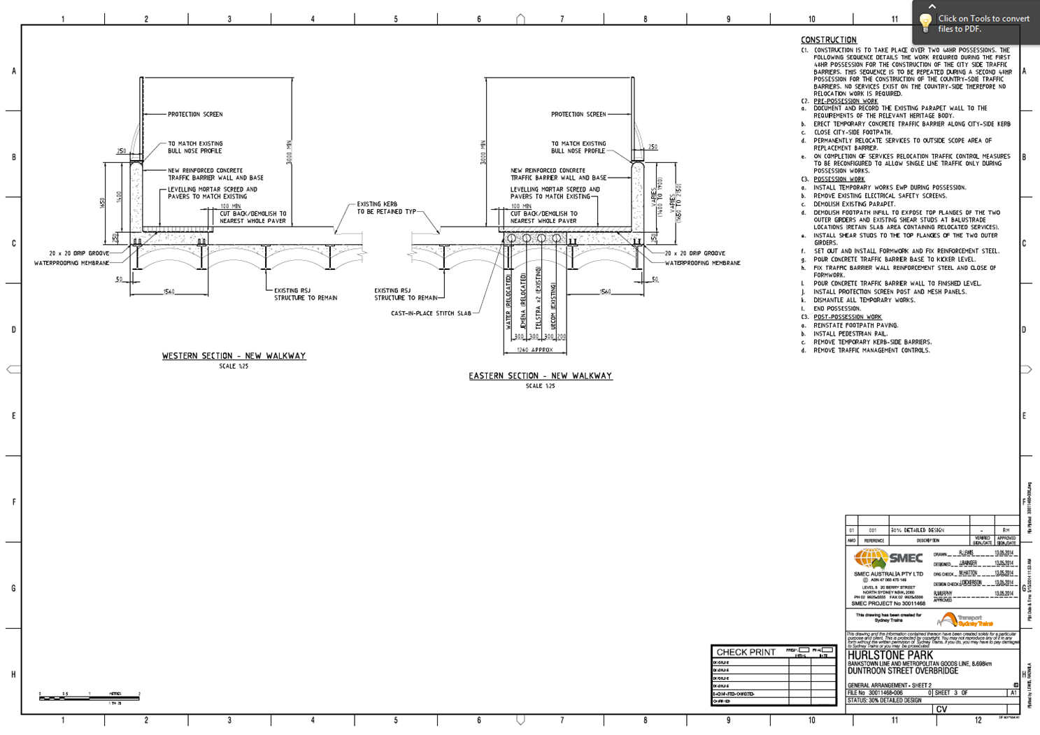
I seem to be the popular choice at the moment to compile and submit tenders, which doesn’t seem to be affected by the fact I have not won any yet because I have just received another one (no doubt my last) while also currently managing three design projects. Over this attachment I have been involved in nine projects (6 tenders and 3 design/PM). The one I have been working on intermittently over the last few months is the detailed design of a traffic barrier to replace an existing masonry parapet in order to comply with current standards. I have subsequently designed a cast in-situ barrier to be constructed on the outside of a 100 year old ‘jack arch’ rail overbridge. I have also modelled the bridge using Microstran to see if the existing structure can accommodate the traffic impact loads. A traffic assessment at the concept stage identified that an intermediate traffic barrier performance was required which stipulates an outward horizontal load of 180kN at 1.1m above road/footpath level, as well as a longitudinal load (to be applied simultaneously) and a vertical load (to be applied as a separate load case). The Australian Standard AS5100 (Bridges) does not explicitly provide a detailed analysis procedure for bridge barriers. As a result, current practice uses American Association of State Highway and Transportation Officials (AASHTO) design procedure based on yield line analysis. The design deliverables for the project are; Concept, 30% detailed, 70%, 100%, IFC. I have just finished getting the 30% DD drawings together to submit to the client (Sydney Trains) by the end of this week in a hope to have the 70% design complete and submitted by the time I leave. I have had to commission a Statement of Heritage Impact (SoHI) and I am now in the process of getting the environment team to produce a draft Review of Environmental Factors (REF) that may be affected by construction such as dust, noise, heritage, social and economic impact to the area. Because it is an overbridge that spans over two rail lines the work will impact rail services during two planned 48hr possessions as well as closing one lane and possible both to vehicle traffic during construction. The amount of work and consideration involved for all aspects of the project all stems from successfully identifying the stakeholders at the very start and you soon realise how many people, organisations and authorities are involved in successfully implementing a project. Below are the drawings at 30% design not showing reinforcement.
I have also been involved in ongoing managerial aspects with the maintenance centre column repair design as per previous posts and a fire protection upgrade design on a cable shaft at central station in the middle of Sydney CBD. I have not carried out any design for this but I have been given the job of PM to bring the project to completion. I also recently submitted a tender for a 1.7km cable route design which was valued at just under $300K with a rather vague scope of works. There was little time to clarify or ask for more detail on most of this – largely because of the fair tendering process every consultant must be informed if a question is asked and meanwhile you lose precious time which you may not have – so I compiled it based on the site inspection and project brief. The client (Sydney Trains) subsequently came back to all the consultants that submitted a bid and have changed the scope somewhat. It appears they put little thought into the original brief and this additional information contradicted previous information. I subsequently revised our originally fee to just under $400K having it reviewed by senior management. The whole episode made me view the client as very unprofessional and rather annoyed me. For instance one comment stated that all assumptions in our proposal should be deleted and the proposal should be based on factual information and the fee should account for the risk accordingly – what planet are these jokers on? It seems very odd – and the seasoned pro’s in the office viewed this in the same way – that the client expects to be entirely risk free. Especially if their own SoW is woolly at best. One of the first tenders I did had a 1000 page brief with various attachments and it was almost too much information, this was a 3 page brief with a rather ‘chip shop’ ppt presentation attached to it. When trying to compile a lump sum fee it very difficult to try and price a project when you haven’t got enough information but you want to be competitive. If the client is not clear on what he wants and asks the design consultant at tender that he is to tell them as part of the scope – which seems quite common in Australia – then surely the client must accept a certain level of risk because the supplier will have to make even more assumptions at the tender stage due to lack of clarity. I would be interested on everyone’s views on this and wonder if any of the other phase 3 lot have been involved in tenders and have had similarly clueless clients?
On other news, the family enjoyed a nice cruise up the eastern coat of Australia at the start of April up to Cairns and the Barrier Reef which was great. Ethan is like the energizer bunny and never stops. Being on a ship meant it was an easy way to travel as your hotel goes with you and by the end of the holiday everyone seemed to know Ethan by name having seen him run about the place for the past 2 weeks with me calling his name trying to keep track of him. It is hard to believe he was only 6 months old when we arrived in Australia and he is now fast approaching his 2nd birthday and Pip is now 5 months pregnant with no.2!

Rejected concrete
Saturday 3rd May has become a dark day on the progress of the Liverpool street station. Following on from the success of the level 106 slab the level 101 slab should have been more straight forward. The amount of concrete to be poured for the 101 level was calculated at 220m3 which was 100m3 less than the 106 level. In addition the steel fixers had work extra shifts to ensure that all the steel was in place prior to the pour, the 106 level had seen steel fixers completing the steel as the concrete was being poured.
With all this in place the pour should have taken only six hours however 8hrs after starting, the pour was not complete. The principle delay to the pour was due to the poor standard of concrete that arrived at site and a miscalculation in the quantity required, with a further 7 loads having to ordered.
At the pre pour meeting on the Friday I had raised my concern over the fact that the previous pour had seen concrete being pumped into form work before the slump tests were complete. If any of the slump test had failed dramatically we would have had severe difficulties in removing the failed concrete or even identifying were it had been poured. In my mind this would have meant the entire slab would have not met the required strength. With my concerns aired I found myself armed with the clip board and in charge of the slump test. Unfortunately this would result in me being struck of many a Christmas card list. The concrete supplier, Cemex, had won the contract based on price. Although I don’t have the exact contract comparison details, I have been informed that Cemex use their own brand of additives to keep cost down however this would seem to have disastrous consequences on their mix.
The concrete specified was a C50/60 mix and the slump was specified between 580 – 620 average diameters. The first delivery of the day managed a less than impressive 520mm. A discussion with the site engineer saw the concrete accepted. However the second delivery spilled off the slump testing board managing a estimated diameter of 680-700mm. Further discussion with the site engineer and the Cemex technician saw the concrete accepted with promises of improvements in the mix. However this inconsistency was set to continue and of 34 loads (full load 7.6m3) of concrete on order I ended up rejecting 6 loads with the majority of the remaining loads being highly questionable. Many of the questionable loads that were accepted were overly loose rather than stiff. Despite failing the slump test they were accepted on the basis of perceived risk of the concrete reaching the required strength against the risk of creating a cold joint.
A cold joint is formed when the time between concrete loads is sufficient to allow the curing of the poured concrete to be different to that of the next load, ultimately creating a concrete joint. As the position of this joint can’t be controlled this can result in a weakness as this may be at a steel reinforcement lap joint or an area of steel without the required anchorage to achieve the required tensile stress.
The risk was transferred to Cemex with verbal and written confirmation that the concrete will reach the required strength. Despite this reassurance from Cemex this does not sit easy in my mind as the question that was not addressed was whether the concrete strength would be reached in time to allow us to strike the formwork and then to excavate.
In addition to the structural issues the loose concrete also prevented the power floating of the surface to achieve the required smooth finish. Power floating requires the concrete to be firm enough to be stood on with enough flex to allow the power float to smooth the surface. Three hours after completing the pour the concrete was to loose to power float and a paddle finish had to be used to complete.
This has thrown up a number of contractual issues concerning the strength and finish of the concrete. The concrete was required to meet 30Mpa cube strength in 24hrs, however this took over 48hrs to achieve. The delay has had the knock on result of delaying the excavation through the 101 level to the 95 level. With over 3000m3 of soil to remove the two week excavation to working level is now going to be very tight with very little scope for further delays due to unforeseen ground conditions. The finish surface of the concrete is to be exposed the paddle finish applied as power floating could not be achieved has had to be raised a s a ‘Non Compliance Report’ and negotiations with the client and designers have continued throughout the week to seek a resolution and to avoid arbitration.
Strong as a Kit Kat – Part 2
The last blog saw me trying to understand the issues surrounding the high failure rate in the concrete in the primary lining, with respect to flexural strength. In a pincer movement reminiscent of the Zulus at Rorke’s Drift, Richard and John exposed my mild bluffing surrounding the testing procedure….
So here is me attempting to be John Chard…
Why test for flexural strength?
Concrete is a brittle material with a low tensile strength. Adding steel fibres to the mix will enhance toughness and ductility defined by the BS as follows:
Toughness – the ability of fibre reinforced concrete to sustain loads after cracking of the concrete ie its energy absorption capacity
Ductility – general ability of the material to sustain load beyond a yield point that defines the limit of elastic behaviour (onset of cracking). (Concrete without reinforcement would be brittle and demonstrate an abrupt loss of strength beyond elastic range.
The sprayed concrete that delivers the structural propeties of the tunnels is steel fibre reinforced (SFR).This ensures that the structure is able to sustain significant ground movements without sudden brittle failure. Therefore the trials procedures will seek to test the ‘Residual Flexural Strength’ ie the flexural tensile strength retained after cracking.
Testing
The CrossRail specification for Sprayed Concrete Linings specifies BS EN 14651 as the test method for approving:
1. Flexural Strength
2. Residual Flexural Strength
The test beams are centrally loaded as shown below, by the 3 point method. The specimens are notched at mid span to induce a crack via stress raising
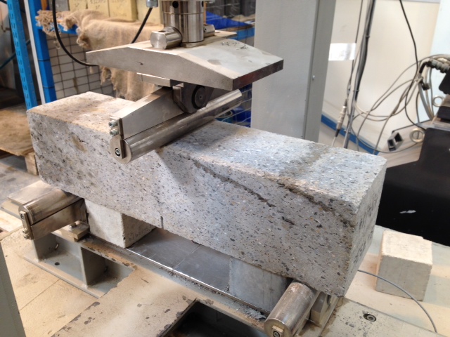
Performance of the test sample is specified by the relationship between the applied load and the Crack Mouth Opening Displacement (CMOD). This measurement can either be measured directly, or calculated in terms of central deflection
Measurements are taken as follows:
F(L) is the load corresponding to the limit of proportionality (LOP)
F1 @ CMOD1 = 0.5mm
F2 @ CMOD2 = 1.5mm
F3 @ CMOD3 = 2.5mm
F4 @ CMOD4 = 3.5mm
The slide shows a typical graph of load, F, against CMOD (BSEN 14651:2005)
Flexural Beam Test Correlation
Flexural Strength
f(L) is calculated in terms of the centre span load, F(L) as follows:
f(L) = 3FL/2bh
h = depth of beam above the notch
b = section width
L = span
Residual Flexural Strength
Crossrails specification tests values of residual flexural strength @ deflections of 1mm and 4mm respectively. However, this is not measured directly, and is measured as a CMOD, which adds an approximation to the calculation (I’ve asked the test centre why they do this…awaiting response). At these values, the beam must retain values of 1.8 and 1.4 respectively.
REFLECTIONS
1. CMOD v Deflection. Other than reliability of measurement, I dont know why CMOD would be used over direct deflection measurement (yet). Whatever the reason, the approximation adds a level of uncertainty that we can ill afford. The example test result above shows a beam which has failed, by a tiny amount, and which is typical of many of the beam failures. Perhaps a wider understanding of this testing method may mean that a tolerance is imposed such that this group of slim failures may edge over the line and achieve a pass?
2. Testing Method. Prompted by the Great Orator, I considered the 3 point testing method as discussed above. This method implies a failure method of coexistent shear and bending. 4 point testing methods for pure bending are specified in the EFNARC beam test (European Federation of Producers and Applicators of Specialist Products for Structures). The BS EN 14488 beam test largely adopts this method, and is mentioned in the CrossRail spec under structural requirements. I’m wondering whether the performance requirements were designed to one test procedure (4 point), and the 3 point test, and its differing pass criteria, were defined for use?
Am I John Chard yet????????
Mr. Blue Sky
It is official, summer has arrived in Scotland. You can tell because the fog is slightly less wet, the rain falls at 45 degrees to the vertical (rather than 80) and it is no longer dark all of them time. It also means that my cycle commute can take some of the more scenic routes…

The last few months have been quite intense, hence the lack of blog posts, but finally Edith has arrived, thesis is submitted and I can actually get back to some kind of a semblance of life.

It turns out that the normal returning to work chills were unwarranted (as usual) and things have progressed well in my absense. Not in the least with thanks to one of my BP colleagues who babysat my portfolio over the four weeks. I no have a confirmed date for the final Minox commissioning, my HP cooler funding has come through and my Caissons DSP have been endorsed by the business.
Minox
Just before I went on leave, this project stalled right at the end of offshore execute due to a missing suction strainer. This stainless steel witches hat strainer sits pointing into the flow to catch debris left in the pipes during construction. The tolerances on the B blower that we have installed are <1mm and commissioning without it would have been high risk.
The piece was found to be missing during the pre-commissioning line walks, it had been missed at every stage of the project, including my review of the project as I took it on. Added to that all we have to go on are the mark ups on the P&ID and Isos, not design data actually exists for the kit. This has resulted in a project change to the tune of £75. £32k for the re-mob of the commissioning team, £43k for the design of the new strainer and about £200 for the strainer fabrication itself…

An example of a typical witches hat strainer
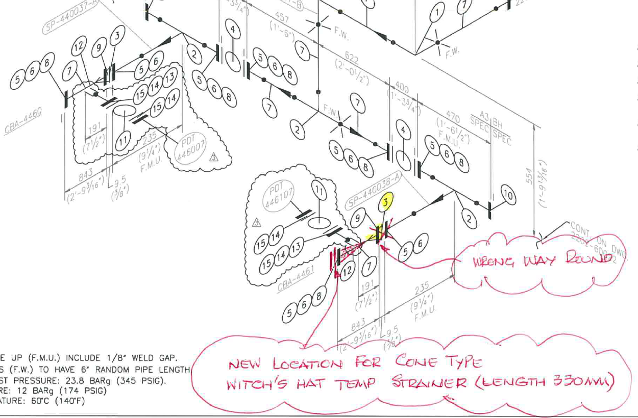
The amount of detail the team had to go on.
The were a few small issues to quell on my return to work, but I now have confirmed dates to complete this project and it will be one of the last things that I do before I leave here.
HP Cooler
My funding bid for this project has now come in and my final budget has been increased from £6.2m to £8.5m. Of that £2.3m I have alread spent around £400k and the rest will be for Nick to spend as he takes this project through to the offshore execute in the 2015 TAR. It is shaping up to be a corker with a 5m sq cantilever lay down area needing constructing off the East side of the platform,
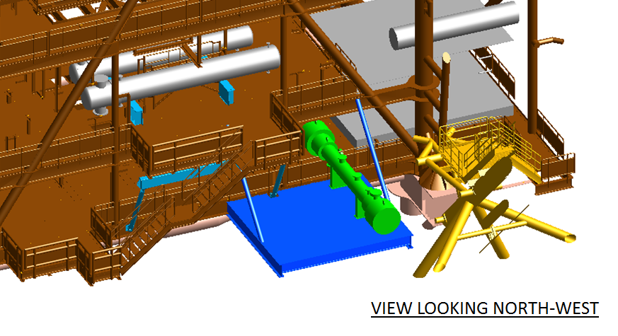
In the picture, the blue element is the new laydown that need constructing, the green is the new cooler and the yellow is the flare boom. Incidentally the silver tubes are the coolers that I helped put in last year. The project itself is nearing the end of the Define phase, but I am finding progress of the structural design team disappointing. Due to a lack of resource in this structural is way behind, process, piping and electrical, which has resulted in some friction. Not in the least that structural identified that the final cooler position needed moving around 500mm; the new cooler is more than double the dry weight of the old and needs to be positioned closer to the main module spars. This has had repercussions on the design work carried out by piping and process which has needed to be modified. I was looking forward to challenging any PCN for this work, but WGPSN has captured it within project growth. At the moment the Define is costing around £100k over the original estimate and I can account for this as due to the fact that the project did not go through Appraise and Select. However, this should put the project in a much better position for Execute.
Caissons
My work on the indefinite postponement of the Bruce caisson programme has come to fruition and my DSP has been endorsed at all levels. This represents around a £20m saving for the business over the next 5 years and potentially more if the risks that I identified are not realised. I still have some work to do in mothballing the C13 project and in reality this will be concluded by one of my BP colleagues on the Bruce team.
In other news
The kids are getting on well, with Hugo just starting to come to terms with the fact that he is no longer the centre of everyones attention. Sleep is still broken and no sign of that letting up in the near future. It is a very good feeling being on this side of the thesis, and for anyone thinking about it completing a thesis and having a sprog at the same time is not advisable.
My last batch of Aberdeen beer is in the fermenter as we speak. It has been going for almost two weeks and has another two weeks to go before it gets bottled. It should be nicely conditioned by 14 July. This is my first attempt at replicating the brew that I made in December and a good test of whether my theory that close control of the fermentation environment will provide consistency in the final product. Unfortunately I have not gotten the fridge rigged up to be controlled by my Raspberry Pi as the SSR arrived to late, but I have programmed a control programme that allows for a low temperature period of fermentation followed by a ramp up in the last 2 weeks. The next iteration of the programme will require some PID control to de-conflict the fridge with the heater and to increase the overall efficiency.
I feel like I have reached the limit of procedural programming and have started to read up on Object Oriented Programming (OOP). This is a more modular approach that will improve my ability to develop the software. It will also allow me to start developing GUI and move towards web and mobile apps. The goal for this would be realtime indication of fermentation temperatures and control of the heater/chiller via a mobile device. It probably seems like over kill for brewing beer (not to me), but then imagine applying the same technology to your house.
New post
Hi All
Good to read of your adventures.
I’ve added some shots to my blog too if you’re interested
http://roselliott.wordpress.com
Good luck for those who are returning soon,
RE
The ground is a risk…(contd)
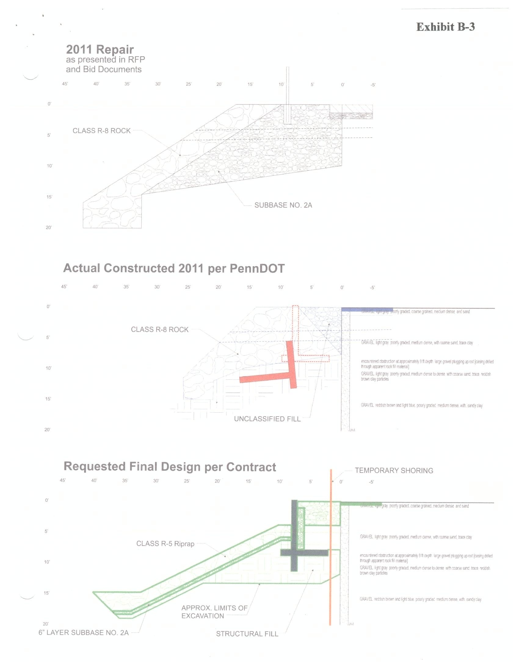
PSB for the cross-sections of drawings. For clarity the top drawing is the repair drawing (inaccurate) that the government provided the contractor in the bid – the vertical protrusion is a fence post.. The middle drawing is the actual representation of the repair that took place – thick red line representing the present loc of the fallen cantilever wall and thick blue line indicating the road and side pavement. The bottom drawing is the ‘as built’ and desired end product. (PennDOT = Pennsylvania Dept of Transport)
The ground is a risk!!!
I always knew the orator’s words would come back to haunt me – it was just a matter of time!!! On the prowel for some more work to complete some more of my DOs, particularly contractual experience, I approached my supervisor 2 days ago to give me some autonomy and contractual experience conscious that the HQ project is mainly sewn up by another project engineer whose toes I have been wary of treading on too much. The response…”I got just the thing fir y’all, why don’t you run with Danville?’ ….Trusting her completely, within hours my desk was covered in paper, emails started flying in, and my head was buzzing with negotiations, primes, change orders, REAs (request for equitable adjustments), …the list goes on!
It is Dev Obj gold dust which is great; I will try to summarise the can of worms on my desk.
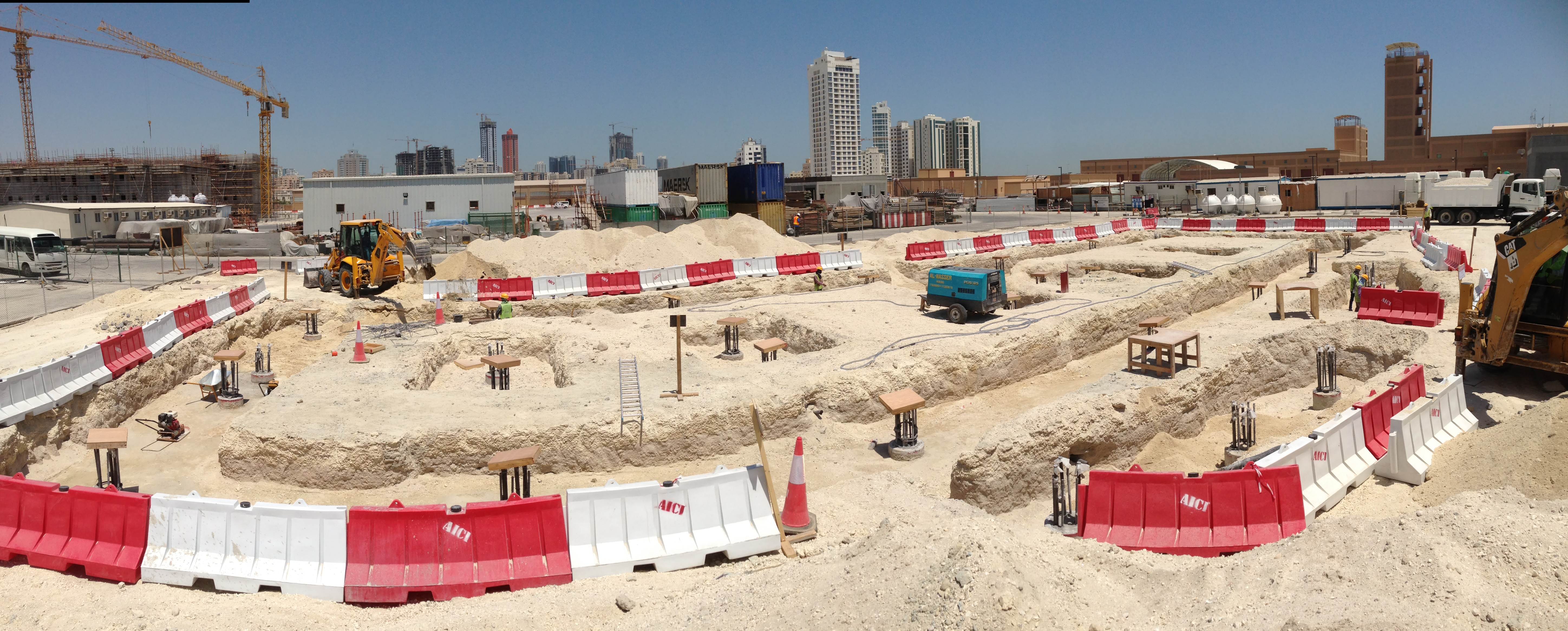
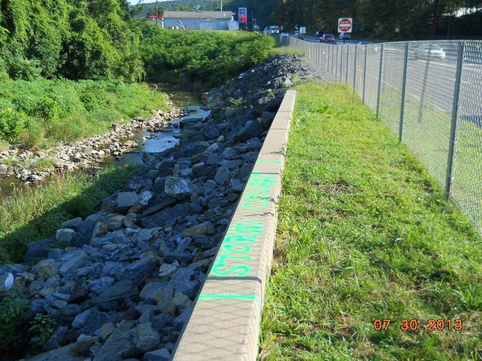
Background: The Mahoning Creek naturally runs into a highway in northern Pensylvania, which has been artificially diverted 60deg’s through the use of a reinf concrete retaining wall (retaining the highway), and embedded within 40” riprap is a concrete cantilever wall (location: http://binged.it/1ugdIxL). Sep 2011 saw a 1 in 500yr flood that undermined the riprap and concrete retaining wall ripping a whole lane out of the highway. Emergency repairs taken by the state were to fill the hole with more rip-rap, aggregate and then road surface on top. The photo shows in the foreground the sound structure; as yuo move away the wall then stops and is replaced by riprap – this is where the wall, riprap and road were undermined – now band-aid’d with a shed load of riprap and a road surface plonked on top. USACE then contracted out the proper repairs; the winning contract deciding to drive sheet piles to hold back the road, whilst the rip rap was removed and a new concrete wall and cantilever with rip rap were installed. However… upon the contractor taking initial boring samples, it was clear that the drawings we provided (courtesy of the local council) did not reflect the fact that there is actually about 20ft of rip-rap rather than the illustrated 3ft!!! The anticipated sheet piles were therefore a non-starter. Works were therefore suspended on 1 Jul 13 until 1 Mar 14, to allow for demobilisation, geo assessment, new permits etc etc, and a new completion date set for 1 Aug 14. The gov also presented a change order for few thousand dollars to compensate for suspension costs
Present/Issues: 1. Work has still not commenced, 2. the contractor has put in an REA for an extension of time as permits still haven’t been attained (what has he been doing all this time?), incl. an REA of almost $100K for susp costs (we estimated about $6K, so this should make for interesting negotiations). 3. Costs for the proposed new construction method (see below) are to be negotiated next week, there is a relatively small delta between our and their estimates (c.$200K) so this shouldn’t be too painful – negotiations start next week which should again be great DO fodder. 4. The geotech investigation has been negotiated to approx $76,000. 5. Funding approval (80% federal, 20% local borough – the latter is the issue dep on the result of negotiations)
The new method statement is summarised as follows: 1. Build cofferdam from haybales and plastic and commence permanent pumping – funding does not allow for grander piling ideas, 2. Construct temp support of the roadway to prevent lateral collapse iot allow for excavation of rip-rap. This will consist of soldier piles and lagging, with soil nails…if curious here’s a great simplified video: http://www.youtube.com/watch?v=hrlBu1d5PBM. 3. Excavate rip-rap, remove collapsed concrete wall 4. Rebuild concrete wall, cantilever and replace rip rap. 5. Replace road and sub-terrain material. I need to get to the bottom of the engineering principles behind the rip-rap and embedded cantilever wall – when negotiations and flashing US$’s calm down I will try and get my head round it. The obvious question of: ”Why rebuild a design that has proved to be faulty?” is that funding for repair projects as a result of natural disasters (provided they have been previously inspected by USACE) is caught up in Public Law 84-99 which grants federal funds for repair; PL84-99 dictates that repairs must be ‘as-built’ unless failure has occurred at least twice whereupon authority can be sought from Congress!! Barking considering the fatal implications and the fact that it has clearly proved it fails if this kind of storm event happens again..but then again the pot has to be tightly controlled!
In short, not a grand project (total contract c.$1mill) by some scales but autonomy, contractual depth, and DO ticks all round.
Projects aside, next week will see Nic and I do some ‘Offr prof dev’ in and around Washington DC with approx 10 other US Army offrs from USACE visiting Capitol Hill, Pentagon, Arlington mil cemetery and major USACE projects around DC (Bethesda’s intelligence university, Spring Valley and the Washington aqueduct), interspersed with fitness tests and some fine wine and dining…thereafter the obligatory family week in Disney! A family pic from a recent trip to DC..
.
Strength of a kit kat!
Throughout my time here on the materials trials team, a constant headache has been the high failure rate of the flexural strength beam tests. The flexural beam tests for fibre reinforced concrete in the primary lining have been failing at a rate of ~40% at 28 and 90 days. For comparison, BFK understand that across all other Crossrail SCL works the rate is down at 5%. It turns out this issue has been going on for months prior to my arrival. The issue has become toxic, with a number of different and conflicting opinions. Unhelpfully, the issue has now become so prevelent that it is being formally discussed and debated in too many forums. Finally, CrossRail have issued an ultimatum…BFK are to provide a robust explanation as to the cause/causes of the high failure rate including action plan by the end of the month, or all SCL work stops.
So here’s what Ive learnt….
Testing.
BS EN 1465 dictates the test critieria. In outline, a set test panels of concrete are sprayed at the face of the advance, at a rate of 1 set/month. Each panel is cut into 3 beams, which are wrapped and sent to TestConsult…our subcontracted test laboratory. The beams are notched at mid section to induce a crack in the centre of the beam. The beam is then tested to failure using the 3 point testing procedure on a Universal Testing Machine….note the band layers in the top right of the beam
As the beam fails, note the faint band layer below which crosses it from approximately 10 – 4 on the clock face. The crack appears to follow the band layer as a failure plane up and to the left. The beam is now loaded off centre, perhaps contributing to a more rapid failure.

The test is dictated by the CMOD or Crack Mouth Opening Dimension. Measured in mm by electrical contacts, an average test result looks like this.FAR 0053-10.Beam & Cores. Note here the Residual Flexural Tensile Strength section…two snapshots are taken…at a deflection up to 1mm, the specification dictates the CMOD must be above 1.8, whilst up to 4mm the CMOD must maintain above 1.4. CMOD is a function of width of crack to length of crack
Action Plan
BFK are beginning to pull together an action plan to resolve this issue. Due to the complexity of the potential contributory factors, they have cast their net widely. Pulling in advice from their parent companies BAM Nuttall and Wayss & Freitag, aswell as specialist suppliers Normet/Tam alongside our own design team. The collective thoughts have distilled down to 6 areas of consideration:
1. Materials/Mix Design.
- A ‘sandy’ texture has been observed on the sprayed material when cured, which may contribute to the laminations. It is possible that this is due to a lack of cement and microsilica (packs the mix and reduces voids)
- Laminations in the beams indicate that the accelerent is reacting too quickly. A less reactive product is being trialled.
- Beam tests have shown fibres ‘pulling out’. This could be for two reasons: firstly insufficient fibre anchorage due to the fibre profile (length, dimensions, shape etc). Secondly, poor concrete ‘grip’. The density of the beam could have been affected by poor compaction, or indeed that the concrete was too old at point of spray.
- Fibre tensile strength. Fibres could be snapping instead of pulling out. Tensile strength currently 1200N/mm2
2. Spraying
- Nozzlemen competancy and technique varies significantly. In addition, the pump speed can be adjusted over a flow rate range between 8 – 22 m3/hr. High flow rates can lead to poor compaction, high rebound and affect fibre orientation.
- Accelerator dosing. Dosing can be varied on the machine over a range 6%-8% and it has been seen that higher dosing making the concrete cure quicker could be leading to higher lamionations
- Test panel. Perhaps the most signinficant factor in spraying is that the test panels are not representative of what is going on in the lining. The panel area is clearly small, meaning that the nozzle movement is smaller leading to increased rebound which is caught in the layers.
3. Plant
- Mechanical factors. Each of the suite of spraying machines work slightly diffently, but critically the concrete is dosed at the nozzle by pump. There is a period of pulsation…flow of concrete…flow of accelerant…before a constant flow is established. When the rate is slowed to spray into the panel, this phenomenon is exacerbated, contributing to laminations.
4. Testing
- Test house procedures. Are the testing houses complying with standards. Members of the quality team have been despatched to conduct a ‘surveillance’!
5. Environment
- How well are the panels and beams protected from damage? The panels are demoulded at 18hrs, before being cut and transported. This demoulding is conducted by using plant to lift and bang out the panel from the mould. There is definitely a likelihood of damage.
6. Batching
- Conducted by concrete subcontractor, Hansons and therefore outwith of our quality control procedures. Fibre storage is important..if not properly protected, they will rust detrimentally impacting their strength..
- Fibre dosing. Is trhe required amount being added to the mix? This is checked by a process of fibre wash out, and weighing samples which arrive at site. These tests are mandated to be conducted monthly, so perhaps the frequency of testing needs to be increased?
- Mixing. Fibres are poured into the back of the wagon at the end of the process, relying on the motion of the concrete lorry to spread them throughout the mix. There has been evidence that fibres in some instances, ball up together and are not spread consistently throughout the mix.
REFLECTIONS
Technical. The factors affecting the many and varied, but in most cases they are measureable. Whilst I have detailed a number fo factors above, the root causes seem to be related to the presence of band layers in the test panels, which cause a failure plane. There is a definite correlation that says the higher the number of band layers in the specimen, the more likely and quicker it will fail. The reduction of the band layers is withiin our gift, as many of the contributing factors occur on site. Secondly, the issues surrounding the steel fibres, are easily resolved, but are entirely under control of the concrete supplier.
Managerial. This management of this issue has been dominated by infighting and opinionating. It has become very devisive…criticism of the mix design means criticism of the materials team…criticism of the workmanship means criticism of the site operatives…an one thing everyone agrees on is criticism of the concrete supplier. Therefore people have become very emotive and unwilling to sit down with a blank sheet of paper and revisit every aspect of this process. Until now. It has taken an ultimatum from CrossRail to drive BFK to go outside of their team and bring in the big guns. This has meant an objective study carried out without the emotional baggage of the last few months. Consequently, a detailed and far reaching root cause analysis was conducted with a very thorough and logical action plan which will test and discount each theory individually. This process has taken 4 days….versus 9 months of bickering.
Contractual. To my mind the concrete conctractor need to be held to account. I suggested having BFK quality assusrance reps at the batching plant…turns out they have reps down there. 2 materials techs who no one can ever reach for comment. It feels to me that this needs to be upgunned, but I darent suggest it for fear of getting the job.
After all that though…I’m not sure why we just don’t go and ask what the other contractors are doing/not doing and make sure we do the same! Maybe thats just not the done thing around here….
An alternative view of the South Bank Tower from Tower Crane 1