Archive
Chalk and Cheese
I am by no means the computer room cooling specialist at the design office but I have been given another computer room cooling survey job to do. When the work was suggested I jumped at the chance to actually put into practice some lessons learnt from my work at Ft McNair by repeating the process, something I haven’t had the chance to do too much of. A good tick for C4.
The job is a survey and cooling design solutions for the communications closets in the ‘big shop’, USACE’s HQ in Washington DC and the reason I was selected is again because I am the cheapest engineer in the office. This has led me to two thoughts. Why is it always the communication closets that we get called in for? And to compare the clients.
Please won’t somebody think of the communication closets!
Both at USACE HQ and Ft McNair (https://htstrial.wordpress.com/2015/11/11/the-blind-leading-the-blind/) the main server rooms are well served with independent cooling systems. However the communication closets, which largely contain switches for VOIP phones and computers as well as some AV equipment, do not have specialist systems if they have cooling at all. My thoughts of why are:
- If communication closets are added retrospectively as part of a small refurbishment dedicated cooling is either not considered or gets deleted to bring a project under budget because it is a discrete, and possibly disproportionally large, cost.
- In new builds or large office fit outs, because the rooms are small and dispersed by their nature, they are just tied into other systems. Again either because it is easy, or cheap unlike dedicated DX or VRF systems.
- Modern equipment has a higher heat density than its predecessors.
- Creeping regulation. It has been recognised for a while that server rooms require security, indeed I wasn’t allowed into one as I am a dirty foreigner. However the security regulations for communications closets has more recently upgraded them noting their risk. Therefore putting a large efficient grille in the door, leaving the door open or even just putting the switches in the main office are no longer acceptable. But asking the ‘so what’ has been a little slower…
- Any other opinions welcome.
Differing clients.
These clients really are chalk and cheese. This was highlighted by a number of the actions of the USACE HQ team.
- They invited stakeholders. Though I didn’t see who would be paying, I got the warm fuzzy feeling that it wouldn’t be an issue. The facility manager and his assistant, who understand the building which is leased, were there as well as the guys who actually worked on the systems in the rooms. And they were all engaged with the effect they wanted to achieve. At Ft McNair we had a quick chat with the FM, were told they wanted portable coolers, and palmed off with a disinterested programmer who roughly knew where the rooms were.
- They were compiling lists of equipment and its heat rejection. This really is the boring part of the job, which I would be doing, so in my eyes they can pretty much do no wrong. Ft McNair did not have equipment lists. Though presumably they would need them for other purposes than just ours.
- I won’t labour the point but they also had as built plans, answered our RFIs on the spot and were able to talk about emergency power and would research more into the availability of capacity.
So what? Well they actually seemed engaged which made the survey straight forward so, rather than measuring rooms and photographing nameplates, we were able to think and talk through wider issues and solutions. The budget is a lot smaller at $3,000, vs $50,000 for Ft McNair, and Mary has spent half of this just by spending a day out of the office. However, it doesn’t appear that access to money is an issue and as I will be doing most of the work it is irrelevant. My conclusion is not that they are doing the legwork for us because they are short of money, but rather that they are engaged with the project and want to get a positive solution.
Design management and leadership
Sorry Mike. No pictures.
You are sure to have heard this phrase before: ‘Sandhurst is the best leadership academy in the world’. I have always had mixed feelings about all that and whether we as the military are as good as the rhetoric, but maybe I’m wrong. I’m not sure if others have had similar experiences in the industry. There were plenty of ‘tense meetings’ in construction, though I can imagine more shouting goes on away from the client; I didn’t really expect it in design though.
I’m not sure if there is any more background to him but the project manager on the Ft Drum NCOA is apparently a known bully. This week’s conference call a shouting match ensued between him and the generally mild mannered design manager. It certainly wasn’t my place to jump in and so I joined my colleagues in gently turning down the phone volume and letting the storm pass. Why? The issue was about a design freeze that had been issued by the project manager due to a VE modification (cutting a 12” slice out of the centre of the building, which clearly has architectural and structural implications). The project manager was arguing that although drawings couldn’t be updated there was still other work that could be done.
So what? The issue with the management of the project in my opinion comes down to two things: communication and the long handled screwdriver:
- On the communication front the project is terribly managed. Meeting minutes are only produced because the Fire Protection Engineer and I produce them as a de facto rather than de jure Other information is continually asked about despite there being a well set up folder structure for IM. Finally, and most relevant in this case, no one had actually told my office that we were to stop modeling; which I pretty much spent the whole of last week doing!
- As for the long handled screwdriver, the project manager is stepping on the design manager’s toes. He has been directing some of the designers and clearly keeping the design manager out of the loop; linking back to communication. Also, and it may just be a bugbear of mine but he uses the word ‘I’ too much as if all the decisions are his; which clearly they are not as he is neither the designer nor the client, rather a conduit for information.
Coming back to the shouting match what really surprised me, and the other Baltimore designers, was that they were arguing in front of us. Whether there are issues in the background or not this does not appear to be the basis of good team building.
Friday Night in Harrisburg
All new buildings are required to complete an Air Barrier Test (ABT) and the Defense Logistics Agency (DLA) HQ is no exception. The leakage rate is important because it indicates how much conditioned air is being lost to the outside environment. It costs money and energy to condition the air inside the building and so it is wasteful to allow it to leak out. More specifically, as the client USACE specifies an allowable leakage rate and if the building fails then the issue must be resolved. Given that the leakage rate is determined by the construction method of the building and this building is very much in the stage of finishes being applied there would be no quick fixes if it fails; so it’s important.
The test was completed on a Friday evening a couple of weeks ago with a provision for a test early on Saturday if required in order to avoid interfering with other trades as the building had to be sealed for the test. Dusk is generally considered the best conditions for testing as the dT between the building and outside is the greatest to be able to detect leak causes using thermal imagery. Sadly, as you will see below this doesn’t necessarily make for the best photographic conditions.
The test consisted of sealing up all ‘intentional’ openings, sealing a number of fans into one of the doorways and pressurising the building. The test was completed twice, first subjecting the building to a negative pressure and second subjecting it to a positive pressure. After a short while to allow the building to reach steady state it (where the pressure is not rising/falling) it could be assumed that the air leaking through the building’s skin was equal to the air the fans were blowing into, or out of, the building. The later was measured through a range of differential pressures to give the leakage rate. Whilst the an operator recorded these measurements for the first test, depressurising the building, the air tester and I walked around the building with the thermal imaging camera, and the less technical back of the hand, to identify any significant leaks. Any cold spots in the building skin or cool air blowing into the building were subject to investigation. For the second, pressurisation test, we walked around the outside to do similar but given the scale of the building this was less effective.
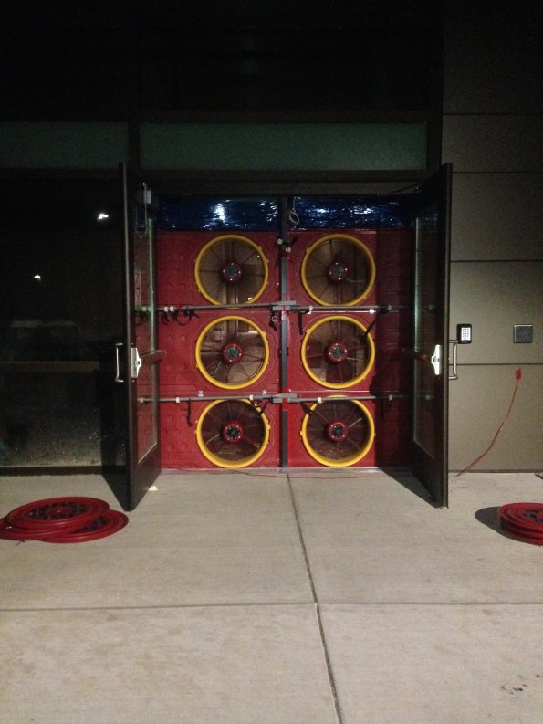
Fan bank 1. A second bank of 3 was put in a nearby doorway to provide sufficient flow rate to achieve steady state.

The system needs to read the same pressure at both fan banks. As the right hand bank has twice the number of fans of the left one it has twice the flow rate.
The standard.
The USACE standard is 0.25 CFM/75 sq ft enclosure, meaning cubic feet per minute per square foot of envelope at 75 Pa differential pressure. This, peculiarly for the USA is a single standard whereas in the UK we have a variety of rates to choose from depending on building usage. The units of measure in the UK are m3/hr50/m2, which is m3 per hour, per m2 of building floor area at 50Pa differential pressure. 2 m3/hr50/m2 is the UK standard for a low energy air conditioned office which is about 0.14 CFM/75 sq ft.
In an office building most of the floor area falls into this however, broadly speaking, unconditioned spaces are exempted; meaning that they have to be sealed off from the main building. Large complex buildings such as skyscrapers or buildings with significant restrictions to airflow, such as a single door separating two halves may be split into zones. The DLA HQ can be treated as one zone as there are large open plan areas and multiple stairwells and lift shafts. The building envelope is usually calculated by the Designer of Record (DOR) but in this case was calculated by the contractor, after a year of asking the DOR. The building is 309,240 sq ft, therefore:
0.25 x 309,240 = 77,310CFM is allowable for this building.
The leakage rate is tested at a differential pressure (between outside and inside) of 75Pa, which compares to 50Pa in the UK.
The practicalities of the test.
The sealing of ‘Intentional’ openings refers to closing all of the doors within the doorframes as well as any HVAC vents, kitchen flues and the waste vents. To ensure optimal pressure equlaisation within the building a few measures had to be taken:
- For every 500 sq ft of suspended ceiling at least 4 sq ft of ceiling tiles must be removed to promote pressure equalisation.
- All internal doors had to be wedged open; fortunately many aren’t fitted yet.
- The doors to the lift shaft had to be wedged open to ensure equalisation to the rooftop mechanical room.
The biggest issue was doors blowing open on the tests destabilising the pressure. The prime contractor had let all of their guys go, for the day, to ensure good running of the test having people, with some form of comms, ready to chase down open doors would have made the whole process a lot simpler. Having plenty of guys on standby would be something I imagine the RE would have got right!
Six of the nine fans used drew a maximum of 3kW. Each of the 230V circuits (the building has 110 and 230V circuits) had a 15A breaker meaning that it could only support one of these fans, or two of the smaller 1.5kW fans. This resulted in about 30 minutes of getting out electrical drawings, resetting breakers and moving extension leads around. The master electrician could have planned this prior to the test.
Results.
In the end the building passed with ease however there were still some interesting elements. The biggest loss areas are:
- Doors. Being freely moving there is always going to be a level of leakage through these. If the building had failed by a small amount then upgrading the seals would have been a way of marginally improving performance.
- Although none of the windows open, as they are penetrations into the buildings skin they act as a potential break and pathway. One window had a good breeze blowing through it that could have been sealed with a bit of mastic if required.
- Sockets and fittings, both internal and external. Again a penetration into the building’s internal skin where air can finally leak through.
- Architectural Interfaces. This would have been the main problem at the DLA HQ. Where differing building methods meet the interface can cause an issue if it is not properly sealed. An example is the auditorium on the DLA HQ which is essentially another building tacked onto the side of the main building. It was built using prefabricated panels, whereas the main building was cast in place. This had been identified as a risk in construction and was mitigated by the liberal application of spray foam.

A doorway. This is taken on the depressurisation test therefore the dark section is showing cold air blowing through the door seal.

The normal picture comparison was black. This shows an architectural interface between a precast structure and a clockwork construction with facade. As this is taken from the outside the bright yellow is showing warm air escaping.
The results came in last week showing that the building had leakages of 0.143 and 0.132 CFM/ft2 for pressurisation and depressurisation respectively. So it passed with ease in the USA, but might have only scraped through the UK equivalent test because of its complex architectural features.
Leaky Pipes
The main fun last week was that the boilers in FtIG shutdown unexpectedly. The contractor has left site temporarily making things more difficult. The issue is not yet resolved so I will blog it when further progressed. In lieu of that excitement here is a thought on sustainability/serviceability.
After the shutdowns of the dual temperature distribution piping from my mechanical room in FtIG we noticed that significant quantities of make up water are required to return the system to pressure; this means that there is a leak somewhere. To do my bit for sustainability I mentioned this to the client and was met by little in the way of enthusiasm.
Replacing the pipe work had initially been part of the scope of the project but as there was no cost benefit attached to it this element was removed to improve the pay back period of the project. This is because the project was funded based on energy conservancy it had to have a 10 year pay back period. The client that the pipes were leaking however didn’t attach a cost to this.
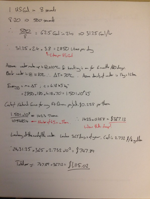
The cost is inconsequential now but for the opportunity to exercise my calculator I have had a stab at it. I conducted a test on site to work out the leakage rate before plunging into a heat loss calculation.
I shut off the pumps and make up water valve and left the system to rest. The static pressure was initially 10psi. To get a representative flow rate for the make up water I used the local tap off to fill a 1 gallon jug, this took on average 8 seconds.
After 2 hours I opened the make up water valve again and timed how long it took to refill the system. By now there was plenty of air in the system from the leaks and so once the valve stopped gushing I restarted the pumps to cycle the system through the air separator with the make up water valve closed to remove the air and ensure the pressure rebuilt to 10 psi. I repeated this process 3 further times until the system balanced. The time on the stopwatch for the make up water valve being open was 8:20. So
This method is clearly riddled with errors, for a start:
- Water leaking whilst I was refilling the system.
- Stop watch error.
- A static condition is not the same as when the system is operating.
- How representative the local tap flow rate test was to the flow rate of the system when nearing 10psi.
- The exact cost of energy and water; I used some figures from Ft Drum. I did an initial calculation using my electricity cost, this came out at $5,400 a year!
However the discussion has to start somewhere and some data, even with a large error value, is better than none.
Either way, had this test been done a few years ago it might have added $11,000 to the budget (or $12,500 if accounting for 2.5% inflation), which might have brought the system within the payback period. I have tried chasing down some of the early paperwork but to no avail.
More pressingly, we are due to treat the system with chemical to preserve the inside of the pipework. The contract calls for testing and topping up the system every month At 31.25 gal/hr the lost water rate is 31.25 x 24 x 30 = 22,500 gallons a month. I don’t know the exact size of the system but assuming 2000′ of 4″ pipework it would be 1300 gallons, which is about 2 days work for our leak. Therefore the contractor will be paying to completely re treat the system each month, significant quantities of chemical will be released into the ground and the treatment of the system will be totally ineffective in preventing corrosion.
I continue to beat my head against the proverbial brick wall on this one…
Non Commissioned Officer Academy Ft Drum
The NCOA will be a mixed use building to house routine NCO promotion training, similar to the Royal Engineer Section Commanders’ Course. The building will house the instructional classrooms, administrative offices, some accommodation, an auditorium, changing facilities and personal weapons storage. It will also house a 15 ft high training area (Room 140 on Figure 1) to be used for drill practice and physical training when weather precludes it from being conducted outside.

Figure 1: Ground Floor Plan.
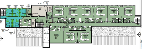
Figure 2: First Floor Plan
The project proposal form had to demonstrate the need for the building, which was that it will replace twenty World War II temporary structures. This will result in a better training environment and reduced utility and maintenance costs. The new building will cover 45,700 sq ft and the project value is currently set at $19 million USD. In order to justify this cost a qualitative economic analysis was executed looking at the alternatives of renovation, maintaining the status quo, leasing and new construction. The status quo was deemed to be unacceptable and other alternatives would have only been a temporary solution.
The project is being contracted as a design, bid, build and the design timetable is organised such that the build contract is due to be awarded on 30 September 2016. This is the last day of the current financial year for USACE and so allows funds to be attributed from this financial year. This presents a risk because if the contract is not awarded on this date then the money attributed to this year will need to be spent on another project or will be lost to the Garrison. I am not privy to information on other mitigating circumstances at programme level, however if some float time had been built into the design schedule this would mitigate the issue at project level. The current design schedule has the following significant deadlines:
35% Design Stop – 18 December 2015.
35% Design Review Conference – 20 January 2016.
65% Design Stop – 28 March 2016.
90% Design Stop – 2 June 2016.
95% Design Review Conference – 28 June 2016.
The date of the planned 90% Design Stop means that I should be able, negating the chance of delays, to see the design work through to this stage.
Given the date of the 90% Design Review Conference it is unlikely that I will be able to see the design through to this point, although the most important experience will have been gained by this point on the design front. The contractual affairs will be dealt with by USACE NY District so there will be no loss of experience by leaving at the 90% design stage.
The design team structure being used by USACE for this design is spread across two USACE Districts and a Design Consultant located in three separate States. The project and the Project Manager is stationed at Fort Drum, NY and is part of NY District. Therefore the design contract naturally falls to NY District’s Engineering Division. Therefore the Design Manager, Architect, Plumbing and Electrical elements are from NY District’s Engineering Branch. Because NY District had insufficient staff to conduct the design of the structural, civil, mechanical and fire protection elements requests were sent to the other Districts within North Atlantic Division. From these Baltimore District was able to staff the Mechanical and Fire Protection elements. As no districts within the Division could support the civil and structural elements these were subcontracted to Pond Consulting, a design consultancy based in Ft Worth, Texas.
Because of the extended lines of communication liaison has already been difficult. A notable occurrence was the design model having to be rotated as it was created 180 degrees out of orientation. As each of the designers across three sites had different linked models this took a week of emails and phone calls to rectify. The issue would have been mitigated against if a central BIM manager was employed on the project, however neither Baltimore nor NY District currently have the post filled.
The new building is to be built on Fort Drum which is in the North of NY State for which the design temperature ranges from a winter design temperature of -30°F to a summer design temperature of 90°F. Significant measures, such as the inclusion of glycol in the hot water system, will have to be taken to ensure the winter design temperature can be met without causing equipment damage.
My part in the design will be to assist the mechanical engineer, Tim Wheeler, in the design of the HVAC system for the entire building. Work for the 35% design is a simple design analysis, setting out of the mechanical rooms, as shown in Figure 3, and specifying the HVAC system type. At the 35% design the room layouts, and therefore volumes, should be fixed to allow the detailed design to take place.

Figure 3: Mechanical Room at 35% design, the eagle eyed will notice that it does not line up with the ever changing floor plan. hence waiting until the 35% design stop to continue.
To 35%, as they are discrete elements I have been given a radiant floor design and a Building Lifecycle Cost Analysis (BLCCA) to complete. The radiant floor will be in the training area (Room 140), which is to be used when it is too cold to train outside. The BLCCA is to assess the viability, or otherwise, of using a Ground Coupled Heat Pump (GCHP) system in place of the air-cooled chiller and 70% of the heating load, the remaining 30% being supplied by a Natural Gas powered boiler.
And that’s the situation as it stands at the moment.
The blind leading the blind.
I have now started my design attachment in the USACE’s Baltimore District Headquarters and am currently working on two projects. One of which is a ‘server room’ cooling survey at Fort McNair in Washington DC, which this blog will focus on outlining.

Fort McNair, in the heart of Washington DC. As you can imagine the traffic was delightful.
I have realised my utility, I am cheap, and so have used this to secure some responsibility early. The project budget is $50,000 and, in the mechanical section, the average engineer’s time is billed at $135 per hour. The basic sum on this gives an engineer 370 hours, but add in project manager time, vehicles and other overheads and it can soon be eroded. This is something I will research into for a further blog but the upshot is that this is now my project, and a handsome little mess it looks like to. The scope of the work currently is to write a report on the cooling within a number of server and communication rooms within the Military District of Washington (MDW) office buildings. There are 15 different rooms spread across 8 buildings, built circa 1900, all with vastly different loads and in different conditions.
After meeting with the USACE project manager, the client and the HVAC engineer for the buildings, Don Ruhl (my partner from the mechanical section) and I toured a number of the rooms. As we travelled around it became apparent that not only did the client not know what they wanted; they also didn’t know what they had in the rooms. The photos give an idea of a couple of the rooms and the varying conditions.

Don inspecting the many unsealed penetrations in a small converted basement broom closet. This room had about 12U of switches and had a retrofitted ductless cooling system. It also had a condensate drain to a sump, thus allowing the condensate to re-evaporate and continually cycle through the cooling system.
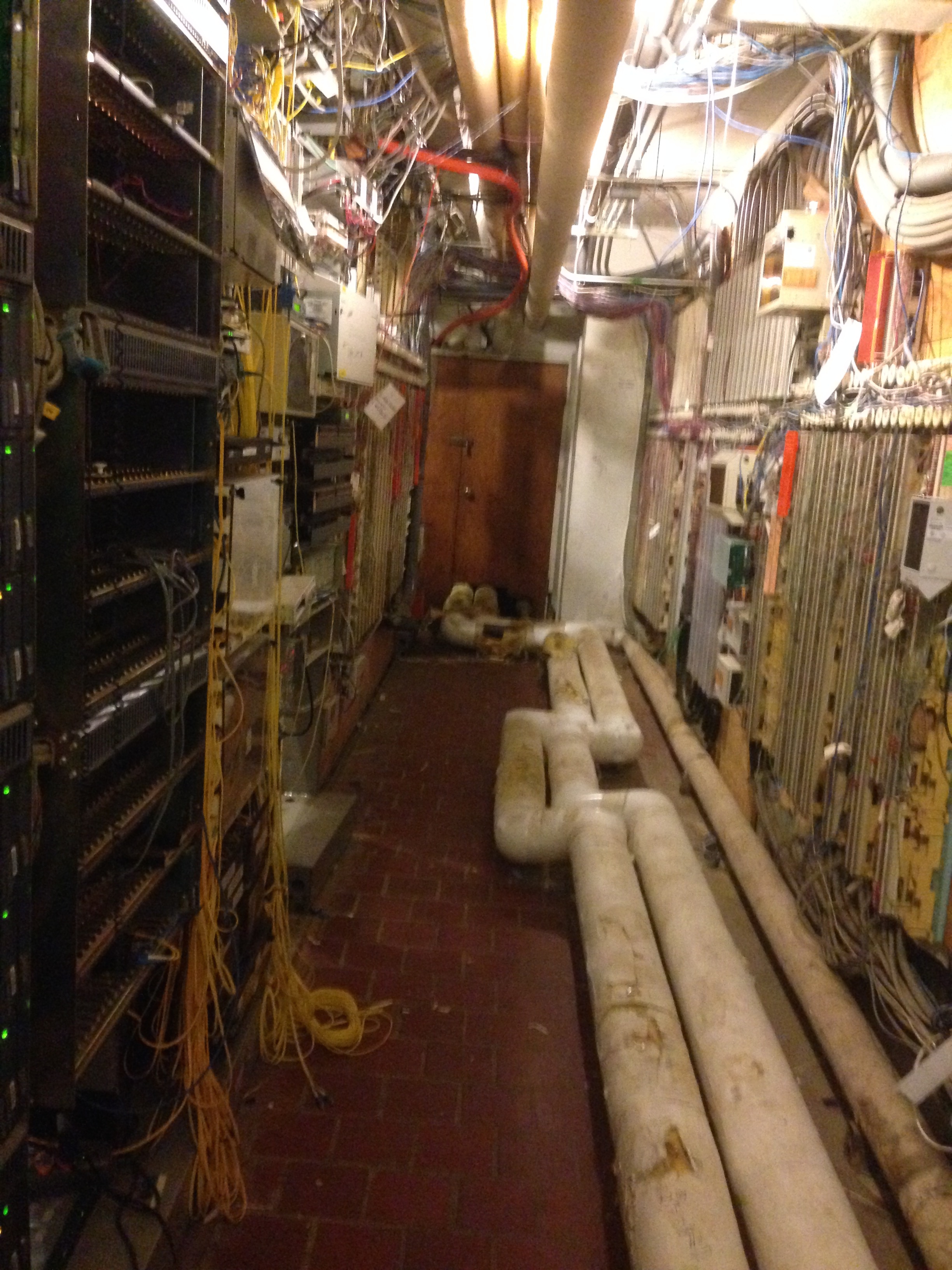
Another basement room with abandoned hardwiring to the Pentagon. About 45U of high grade servers in here. The pipe on the floor is for chilled water with heavily damaged insulation allowing condensate to form on it in the summer.
Server rooms are ideally internal within a building in order to avoid solar heat gains and also because servers don’t need a window to stare forlornly out of. They are usually sealed from infiltration; tidy, to control airflow and have some form of HVAC. The current standard for low and medium density data centres and server rooms is to use a hot aisle, cold aisle system as illustrated below. Cold air is fed from low down in the ‘cold aisle’, either through the floor or by retrofitted ducts; the server blade draws it in through the front and rejects warm air through the rear into the ‘hot aisle’. This rises and is collected by the return air system. As the photos above indicate this was not the case.
Hot aisle, cold aisle process diagram.
So what. Well given the conditions in many of the rooms, even doing a complete survey would be incredibly costly on time. After this initial assessment we need to engage in some expectation management in what we will be able to provide and re-write the scope of our work, which is currently pretty open ended. I see this largely as focusing effort on the more important rooms in terms of upgrades and identifying the risks of each room to the client so that they can make an informed decision.

In an age of BIM, I have been told that the best we can get is a floor plan for some of the buildings so it appears that even a set of out of date as built drawings are a wish too far. Due to this if construction work is ever completed on this then the contract will almost certainly have to be a design and build as the potential for change orders on a traditional contract would be immense!
Finally, a little leadership challenge.
I mentioned earlier that I had been given the lead on this project but I am working with another engineer. Don has worked for USACE design section for at least 30 years and is probably the most intelligent person I have met out here. He has no aspirations of leadership and is very happy to let me control things; however his ability to take a tangent and dive too far into the details too early are something to behold. Certainly a different management challenge from both soldiers and contractors!
Hospital Pass
Part of the role of USACE, as the client’s representative, is to conduct design reviews for design-bid-build contracts (read traditional contracts). These are done at 35, 65 and 95% with comments provided back to the project manager and design team, be it in house or a consultant, through an online system (Dr Checks). The designs are reviewed by us at construction division as well as the design division and are passed out to the clients and facilities managers, probably amongst others.
A couple of weeks ago, due to staff being on leave, I was given one of these to look at the pumps, seemingly alone. Having no idea what to do I browsed the drawings to work out what the issues might be. The project is a new 750,000 U.S. gallon water tower for domestic water and as a fire supply so my pavlovian response was Bernoullis!

After checking the answer it seemed about right although there were no accompanying design calculations to the contract and drawings so I chalked up my first comment. The rest of the checking passed with less excitement. There were a few clauses that had been missed from the contract, some ill thought out processes and demolition elements missing from the drawings. It seems a common theme though that construction division give the most comments, usually about build ability and, as discussed in the past, what is actually existing at the site.
So what have I learnt:
Hopefully I’ve done Bernoulli’s right; simplify the problem and sketches work.
Designers, it appears, live in a magic construction dreamland and it is always the same build ability issues that are picked up. By using traditional contracts USACE does assume a lot off risk and pays handsomely for the privilege if elements aren’t caught by the construction team prior to tendering. Having recently moved into dreamland, albeit part time at present, the fine detail is easy to forget.
And as ever, time spent on recce…
How big is the bus?
I am not sure whether the client usually gets to see the value of each of the subcontracts but it appears that we do. So for my FtIG project I can see that ‘the bus’ is costing us approximately $110,000 or 27.5% of the contract value. From what I have seen so far this pays for two slippery salesmen and an OAP in a portacabin who is going to run the site. Although we are supposed to get the information it has been accidentally added into the emergency contact submittal, which was clearly part of a larger spreadsheet, but you can get the idea

Contract values
Flippant as I may be this clearly also considers the various overheads that have been incurred not least the cost of tendering for the project and the 4 months of paperwork that has been done prior to getting out onto site. This in cash-flow terms is a significant burden for a small company. Also in there will be the risk for things not going well, something that is quite likely in replacing an old system. I am not sure whether Greg or Steve have any thoughts on the general mark up on something like this.
As far as progress goes, yesterday I met the aforementioned OAP who is to be the superintendent, Quality Control Manager and Site Safety and Health Officer (SSHO) and some materials were delivered. I took the opportunity to get some shots of the interior:
Left: Air conditioning unit not being replaced. Right: Two boilers being replaced.
Left: Three pumps, to be replaced with two pumps.
Right: Domestic Hot Water Heaters to be replaced.
Writing a schedule that helps you get paid.
Safe in the knowledge that everyone will be too busy fawning after Mike’s baby…
I just reviewed the FtIG boiler project schedule, again. Now, on version 4, the contractor has lowered my expectations sufficiently that I am now focused only on the money. Their timings for installing pipe work are unrealistically short and everything appears to be on the critical path. These, though annoying, are their problem as the contractor is responsible to ensure there is no gap in service for hot water, heating or cooling within certain seasons.
So resigned to failure on the time side I have turned to look at the money. USACE pay for definable elements, rather than the alternative of paying for percentage complete on the whole job. From the pay reviews that I have conducted for the Waste Water Treatment Plant this appears to be a better form of holding the contractor to account for finishing up individual elements. By paying 98% of an element that isn’t quite finished it leaves a virtual snagging list in dollars. These are more likely to be completed by the next pay period rather than being forgotten until the end of the project, when especially if there is a staff turnover, they get swept under the rug. We will pay for stored materials but, it has to be a significant element, the contractor has to show ownership and we prefer if it at least in place. For this project the boilers and water heaters may come into this but certainly nothing else. Again, for the waste water treatment plant we have paid for stored materials for a $60k generator and a $130k pump set so that really sets the magnitude. I’d be interested to hear what everybody else’s clients’ are happy to pay for on that?
So what’s my issue with the FtIG values? I have two:
To me definable elements are like a product breakdown structure (PBS) and when it comes to pay time I want to be able to go to the element, look at it, tick a box and pay the contractor. This is not me being an idle box ticker rather ensuring that each element is well defined, and I assume this will help them with their sub-contractors. The FtIG programme has not been built from a PBS so I can foresee the arguments coming at pay time. The lesson from this is do a detailed PBS, even for a simple job, because it has ongoing utility beyond just being the start of a programme.
I remember Steve Payne hammering the PBS into us in phase 1 but this experience and if I had any doubt then it has gone. The issue of everything being definable is important too in order to communicate the plan to different people. I am, reasonably, sure that the sub contractor knows how to do this work, however they have not managed to communicate this effectively to the contractor who, in turn, has not managed to communicate it to me. I am sure this is a lot worse in the larger projects with more people involved.
Front loading. The contractor admitted before that the project was front loaded, we all laughed and I told him that we wouldn’t accept front loading. They went away and when version 2 came back it was worse rather than better. I am aware that the contractor requires cash flow. Working for the Federal Government cash flow is not a problem, however I need to ensure that if the contractor goes bankrupt that I still have the money left in the project budget to put the remainder of the contract back out for tender. The solution to us meeting a better agreement actually came from the contractor letting me loose on his values. I can’t pay them any less than the contract value, all I am doing is moving around what the money is tied to. I am sure there will still be more iterations required before we come to final agreement but it’s a start.
In terms of submittals, over here the Navy ask for a ‘schedule of values’ as well as a schedule (programme), but USACE ask for both as part of the same submittal: the schedule. I’d be interested to hear how others have seen this being asked for by clients? For checking on the client side I think breaking them out would be best.
Apologies for the lack of pictures, I have avoided putting the programme in as it is little changed from a couple of blogs ago, and looks pretty difficult to see on a computer screen.
Change!
Since my last blog about the Fort Indiantown Gap progress has been slow. This appears to be as a result of the difficulty from the contractor’s end both in meeting USACE’s various contractual requirements for personnel and an ill defined scope. Following a theme of designers not confirming what is currently in place prior to starting refit designs this had lead to a protracted series of RFIs. Finally to curb this laborious process this week I managed to get everybody into the same room, except for the designer who phoned in, and we managed to thrash through the details.
The issue has come down to the hot water distribution. The original system is shown below at Figure 1 with three separate pumps feeding individual systems. As the H&V unit was removed years ago the demand on P-3 has reduced from 52 to 0.75 Gallons per Minute (GPM). This means it is massively oversized but the designer had just replaced it, he had also labeled it as P-3 on the Boiler Detail (Figure 2) and connected it as if it was a stand-by pump: hence the contractor’s confusion!
Figure 1: Original System
Figure 2: The original replacement design
So as a result of our meeting the contractor and I came up with Figure 3, proof that pen and ink isn’t dead! The other clouds are described below in my contract modification.
Figure 3: Modification Drawing
‘The boiler piping detail shall be replaced with attached sketch MP-2. This modification includes the following:
a. Removal of the three-way valve (known as V-3) from the hot water return to the boiler as it is not required.
b. Removal of P-1 from the detail. Given that the majority of the load for P-3 (H&V unit that has been removed) no longer exists P-3 shall be removed and the remaining active load added to pump P-2. New total for pump P-2 shall be 111 GPM, the pressure drop will remain as currently scheduled given that the distribution system is the longest run.
c. Hot water piping serving CUH, located in the vestibule, and AC-1 shall be connected to the new hot water piping before the summer/winter change over valve such that it does not receive chilled water from the dual temperature side of the system.
d. Two automatic three-way two position valves are to be included as the summer/winter change over valves. These will switch between the hot water supply and return and the cold water supply and return respectively.’
So what?
This is proof to me that the PEW attachment process works, the original system was not designed to be constructed; instead it was treated as a paperwork exercise. This is probably reminiscent of a few Crosby design exercise submissions, however in my defence there wasn’t a building to walk around and design to.
Another valid idea might have been to increase the size of P-3 and turn it into a stand by pump, however the spare budget for this project is small and needs to be preserved for when problems start occurring in construction so we used the cost saving from this to ‘wash’ against the cost of the automated summer/winter changeover valves. Next stop for this modification is a few stamps from the hierarchy and then into negotiation which should be interesting.
Schedule
Another element of the meeting was to review some of the contractor’s submittals that required changing and this included the project schedule. Fig 4 shows my copy of their schedule prior to the meeting. It is probably difficult to see all the detail but the best part is where the contractor has claimed a value of $120,000 for boiler removal and $45,000 for insulation removal, bearing in mind this is a $500,000 contract. The boiler removal will require skilled personnel and some Materials Handling Equipment (MHE), but the insulation removal will just be Spr Crosby with a knife and a bin; so $4,000 and $1,000 might have been more appropriate. When confronted as to why the project manager, without a hint of shame, said: ‘That’s frontloading.’ I’m not sure whether Steve Payne would be proud or ashamed of him but, needless to say those figures will be adjusted.
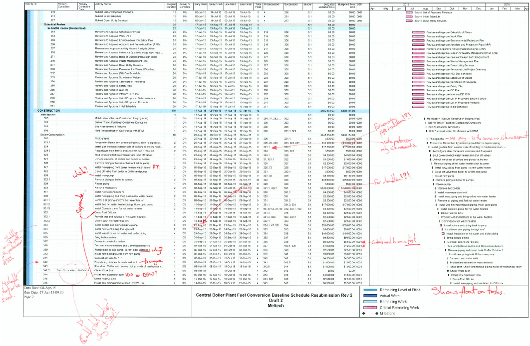
Figure 4: Schedule with my notes.
Looking further into the actual scheduling issues there is little structure which has caused issues. There is a requirement to maintain continuous domestic hot water throughout the project and space is, as ever, tight. It appears to me that no attempt at a Product Breakdown Structure (PBS) and Work Breakdown Structure (WBS) was made which would have aided sequencing of this job.
Signs
The only work that has actually happened on site is the erection of the project signs as shown in figure 5 This also shows a lamppost, and a High Voltage (HV) Ring Main Unit in the background. The consequence of locating the project sign so close to the lamppost and HV Ring Main Unit could have resulted in death as a result of cable strike when digging the postholes. Fortunately, no one was injured in the erection of the sign. As well as the potential outcome for the contractor’s employee erecting the sign, contractor has also not asked for permission to dig. Therefore I took the action of writing a warning letter in order to warn the contractor’s senior management of the error. Also, as this was the first actual work on site, the letter catalogues the error so that, in case further H&S violations are witnessed, there is evidence to remove them from the site.
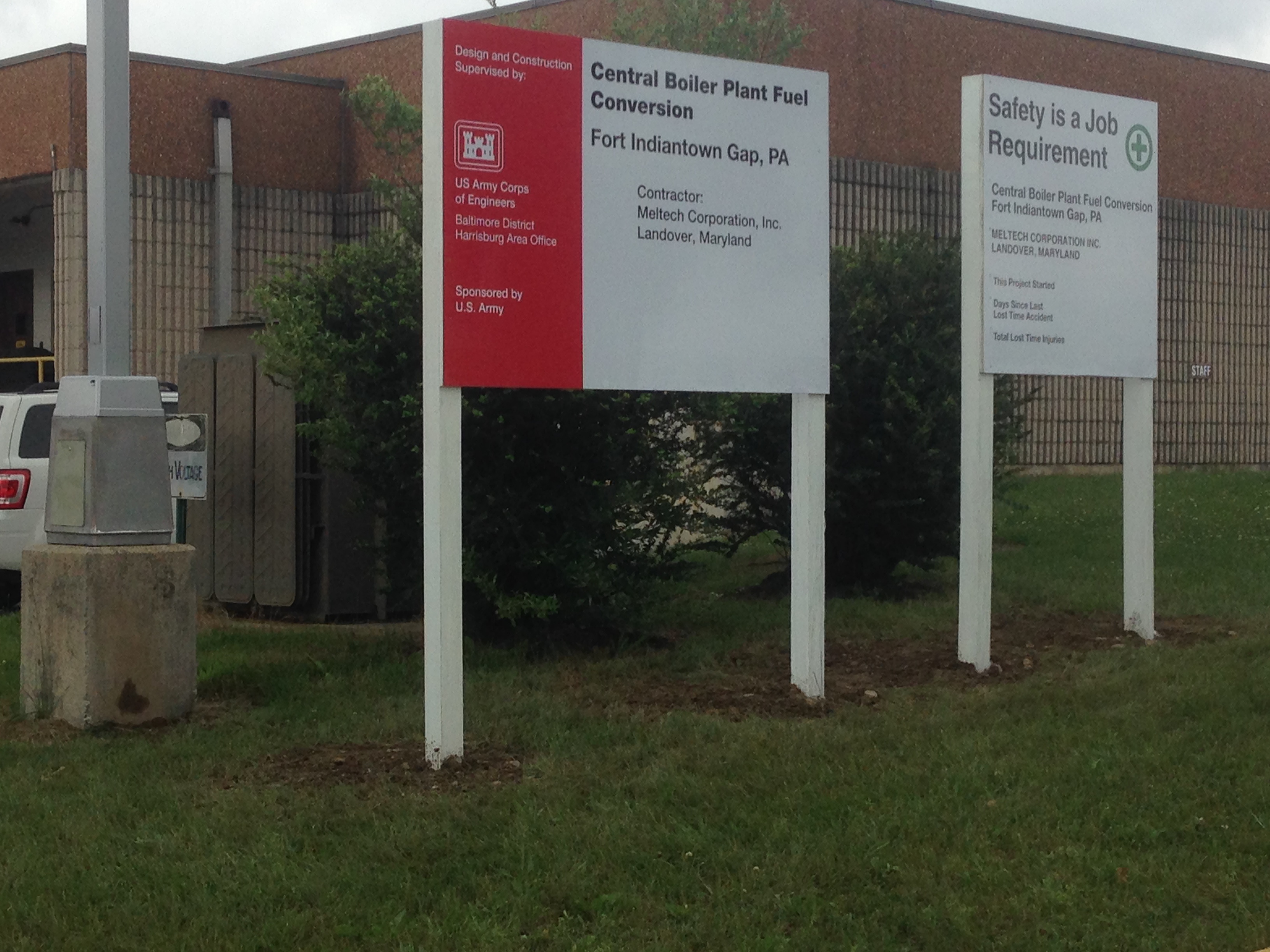
Figure 5: Spot the H&S risks!
