Archive
How big is the bus?
I am not sure whether the client usually gets to see the value of each of the subcontracts but it appears that we do. So for my FtIG project I can see that ‘the bus’ is costing us approximately $110,000 or 27.5% of the contract value. From what I have seen so far this pays for two slippery salesmen and an OAP in a portacabin who is going to run the site. Although we are supposed to get the information it has been accidentally added into the emergency contact submittal, which was clearly part of a larger spreadsheet, but you can get the idea

Contract values
Flippant as I may be this clearly also considers the various overheads that have been incurred not least the cost of tendering for the project and the 4 months of paperwork that has been done prior to getting out onto site. This in cash-flow terms is a significant burden for a small company. Also in there will be the risk for things not going well, something that is quite likely in replacing an old system. I am not sure whether Greg or Steve have any thoughts on the general mark up on something like this.
As far as progress goes, yesterday I met the aforementioned OAP who is to be the superintendent, Quality Control Manager and Site Safety and Health Officer (SSHO) and some materials were delivered. I took the opportunity to get some shots of the interior:
Left: Air conditioning unit not being replaced. Right: Two boilers being replaced.
Left: Three pumps, to be replaced with two pumps.
Right: Domestic Hot Water Heaters to be replaced.
Writing a schedule that helps you get paid.
Safe in the knowledge that everyone will be too busy fawning after Mike’s baby…
I just reviewed the FtIG boiler project schedule, again. Now, on version 4, the contractor has lowered my expectations sufficiently that I am now focused only on the money. Their timings for installing pipe work are unrealistically short and everything appears to be on the critical path. These, though annoying, are their problem as the contractor is responsible to ensure there is no gap in service for hot water, heating or cooling within certain seasons.
So resigned to failure on the time side I have turned to look at the money. USACE pay for definable elements, rather than the alternative of paying for percentage complete on the whole job. From the pay reviews that I have conducted for the Waste Water Treatment Plant this appears to be a better form of holding the contractor to account for finishing up individual elements. By paying 98% of an element that isn’t quite finished it leaves a virtual snagging list in dollars. These are more likely to be completed by the next pay period rather than being forgotten until the end of the project, when especially if there is a staff turnover, they get swept under the rug. We will pay for stored materials but, it has to be a significant element, the contractor has to show ownership and we prefer if it at least in place. For this project the boilers and water heaters may come into this but certainly nothing else. Again, for the waste water treatment plant we have paid for stored materials for a $60k generator and a $130k pump set so that really sets the magnitude. I’d be interested to hear what everybody else’s clients’ are happy to pay for on that?
So what’s my issue with the FtIG values? I have two:
To me definable elements are like a product breakdown structure (PBS) and when it comes to pay time I want to be able to go to the element, look at it, tick a box and pay the contractor. This is not me being an idle box ticker rather ensuring that each element is well defined, and I assume this will help them with their sub-contractors. The FtIG programme has not been built from a PBS so I can foresee the arguments coming at pay time. The lesson from this is do a detailed PBS, even for a simple job, because it has ongoing utility beyond just being the start of a programme.
I remember Steve Payne hammering the PBS into us in phase 1 but this experience and if I had any doubt then it has gone. The issue of everything being definable is important too in order to communicate the plan to different people. I am, reasonably, sure that the sub contractor knows how to do this work, however they have not managed to communicate this effectively to the contractor who, in turn, has not managed to communicate it to me. I am sure this is a lot worse in the larger projects with more people involved.
Front loading. The contractor admitted before that the project was front loaded, we all laughed and I told him that we wouldn’t accept front loading. They went away and when version 2 came back it was worse rather than better. I am aware that the contractor requires cash flow. Working for the Federal Government cash flow is not a problem, however I need to ensure that if the contractor goes bankrupt that I still have the money left in the project budget to put the remainder of the contract back out for tender. The solution to us meeting a better agreement actually came from the contractor letting me loose on his values. I can’t pay them any less than the contract value, all I am doing is moving around what the money is tied to. I am sure there will still be more iterations required before we come to final agreement but it’s a start.
In terms of submittals, over here the Navy ask for a ‘schedule of values’ as well as a schedule (programme), but USACE ask for both as part of the same submittal: the schedule. I’d be interested to hear how others have seen this being asked for by clients? For checking on the client side I think breaking them out would be best.
Apologies for the lack of pictures, I have avoided putting the programme in as it is little changed from a couple of blogs ago, and looks pretty difficult to see on a computer screen.
Two things are infinite.
Einstein said: ‘Two things are infinite: the universe and human stupidity; and I’m not sure about the universe.’ This is a theory I have long signed up to and today I can add another piece of empirical evidence to the data set.
One of the Access Control Points (ACP, or gate in English) to the camp at Harrisburg is being upgraded because of the perceived threat to the site from terrorists. On the security front I could wax lyrical about the fact there is a small airfield adjacent to the camp, that it has the lowest grade of fence in the U.S. military catalogue, or that I could squeeze through a gate on the Northern side of the perimeter fence. But greater minds than I have decreed that the weakness is at the main gate so that is what is being upgraded.
As part of the upgrade the road layout is being adjusted with an alien feature to American roads: a roundabout. I have seen less than 10 roundabouts (or traffic circles to use the vernacular) since being out here and each appears to have its own rules. People also appear to be petrified of them, probably because they are so rare and non-uniform. Because the construction is taking place on an operational road building the roundabout has been phased. It also means that everyone has driven past it for the last two months; which is probably enough of a lead up to know what might happen one day.
On Monday we signed of the transition to the next phase of construction and as a result the traffic route was changed in the afternoon for the next phase. Traffic now enters the camp in a different lane weaves about a bit and then hits the roundabout. To be more precise, only half the roundabout and the idea is obviously that you go ‘round’. So without looking at the artist’s impression below you can probably guess what happened this morning.
My Boss’s sketch of the incident (cameras were banned for security reasons)
A driver had managed to mount her car on the triangular lane splitter at the entrance to the roundabout. When in full operation this apparently shouldn’t be catastrophic as the kerb is ‘mountable’ and the level inside the triangle will be brought to the top of the kerb with concrete. At the moment, half constructed, the inside of the triangle is at road grade level, about 8 inches short of the final level. As she tried to reverse out of trouble she broke off her bumper and has apparently damaged her front axle assembly and because of that the car is ‘totalled’.
So what..
Well it lead me to thinking what could we have done about it. Filling the hole in would have reduced the damage sustained to a vehicle but would have caused rework or having to order in concrete. In the end more cones were placed in the triangle to ‘give more reflection’ as the driver said she hadn’t seen the kerb. My opinion is that more flashing lights and reflective bollards aren’t really going to help if someone is looking at their phone rather than the road and that human nature is always going to cause the odd accident. The best prevention of a future accident is the fact that everyone driving in that morning will have seen the car stranded and might be more vigilant: for a few days.
Fortunately no one was hurt in the accident, something I should have mentioned earlier. This was because, by chance, no work was being done in the area. Maybe, as a safety measure in the future though, a soak time of a couple of days after a road layout change might be a sensible safety precaution in an area where commuters operate on autopilot in the mornings.
The below pictures show the phases of construction for the roundabout. The accident happened in the phase 2 layout moving from the top of the image.
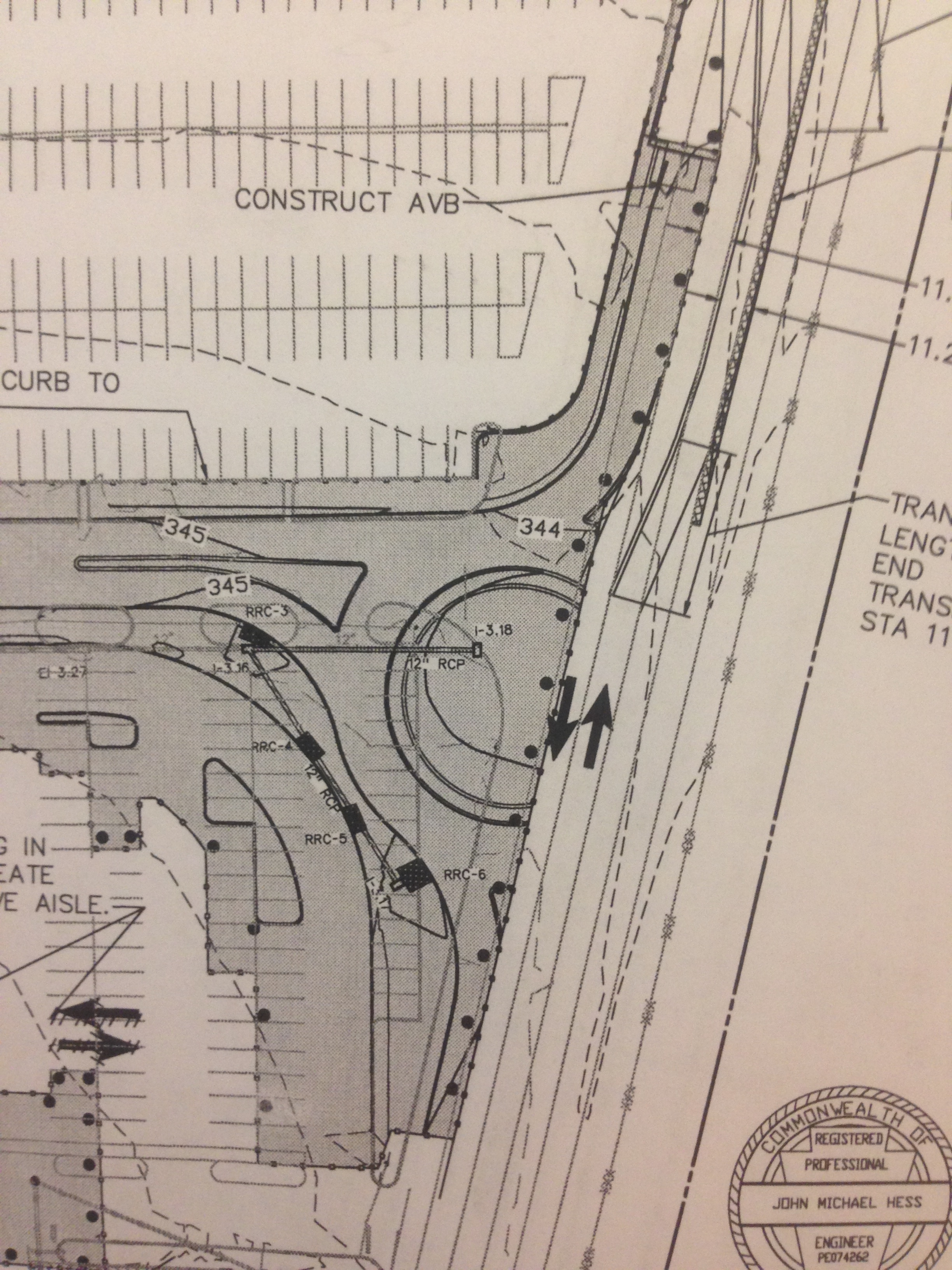
Phase 1
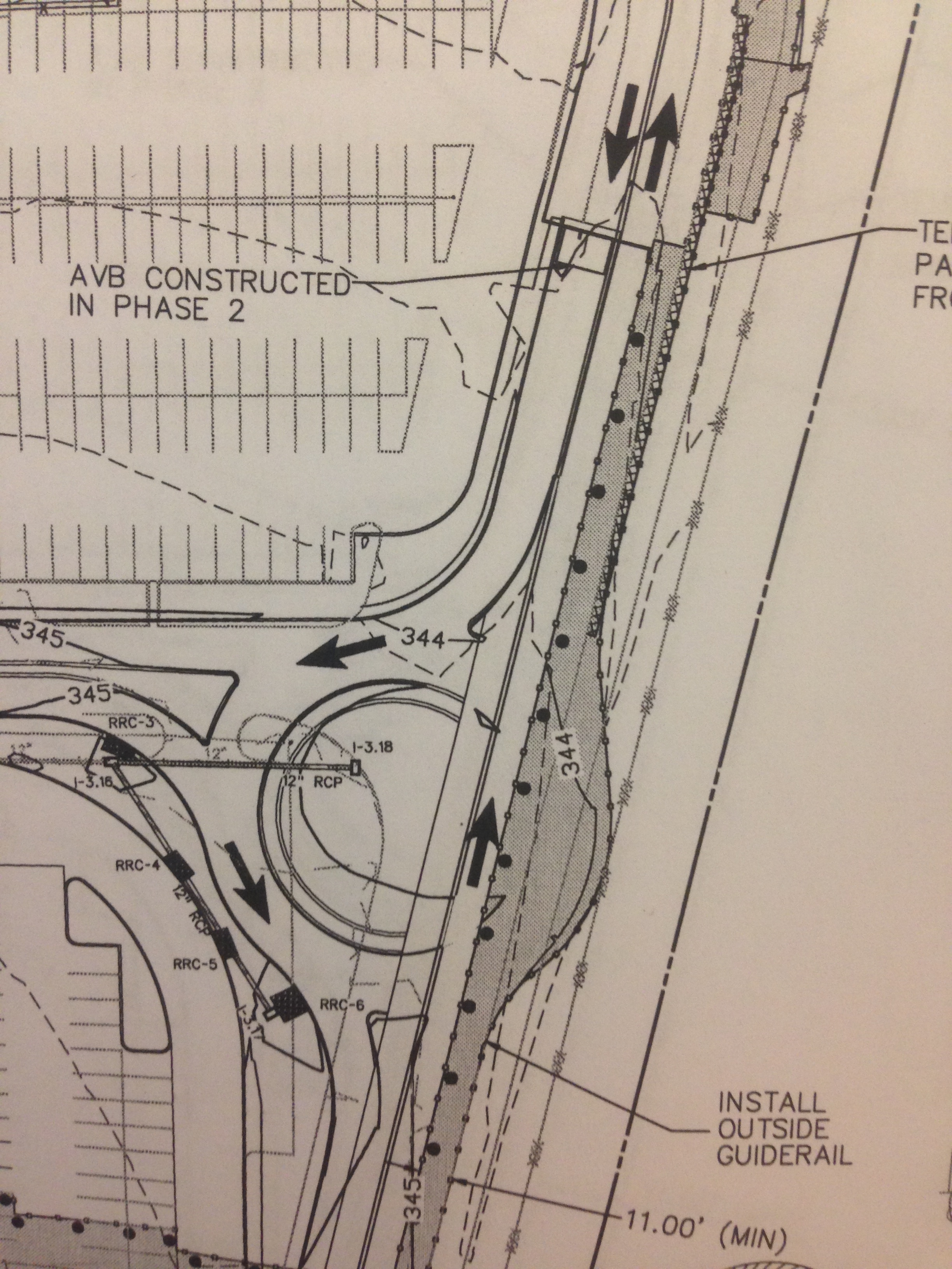
Phase 2 – the phase we have just moved to
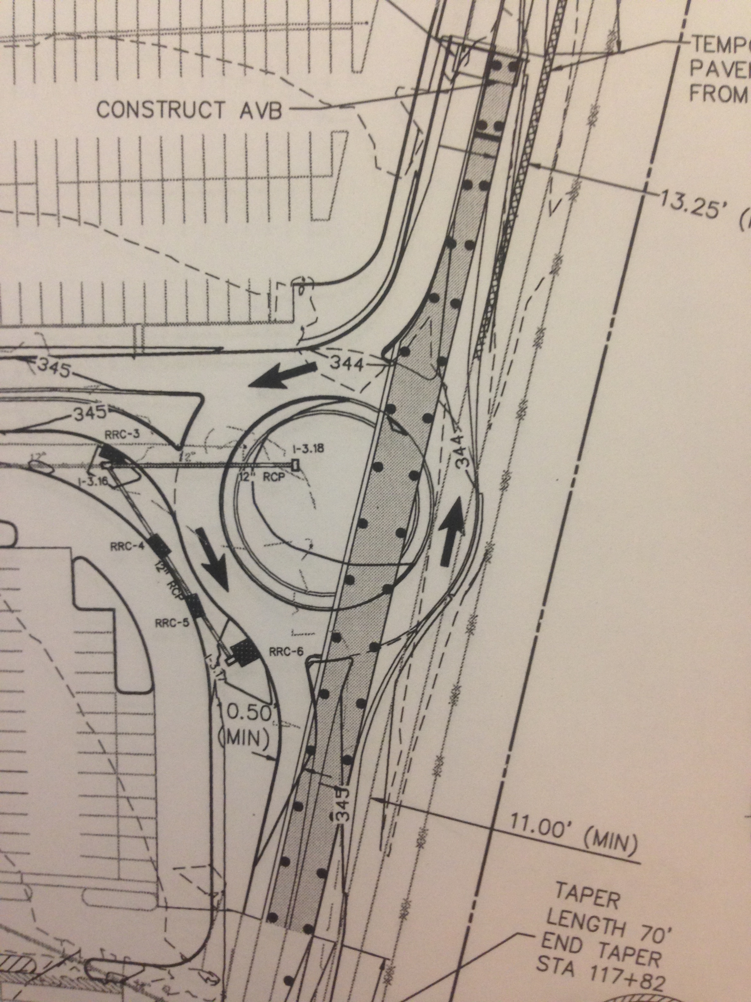
Phase 3 – This will be a safety concern for the workforce
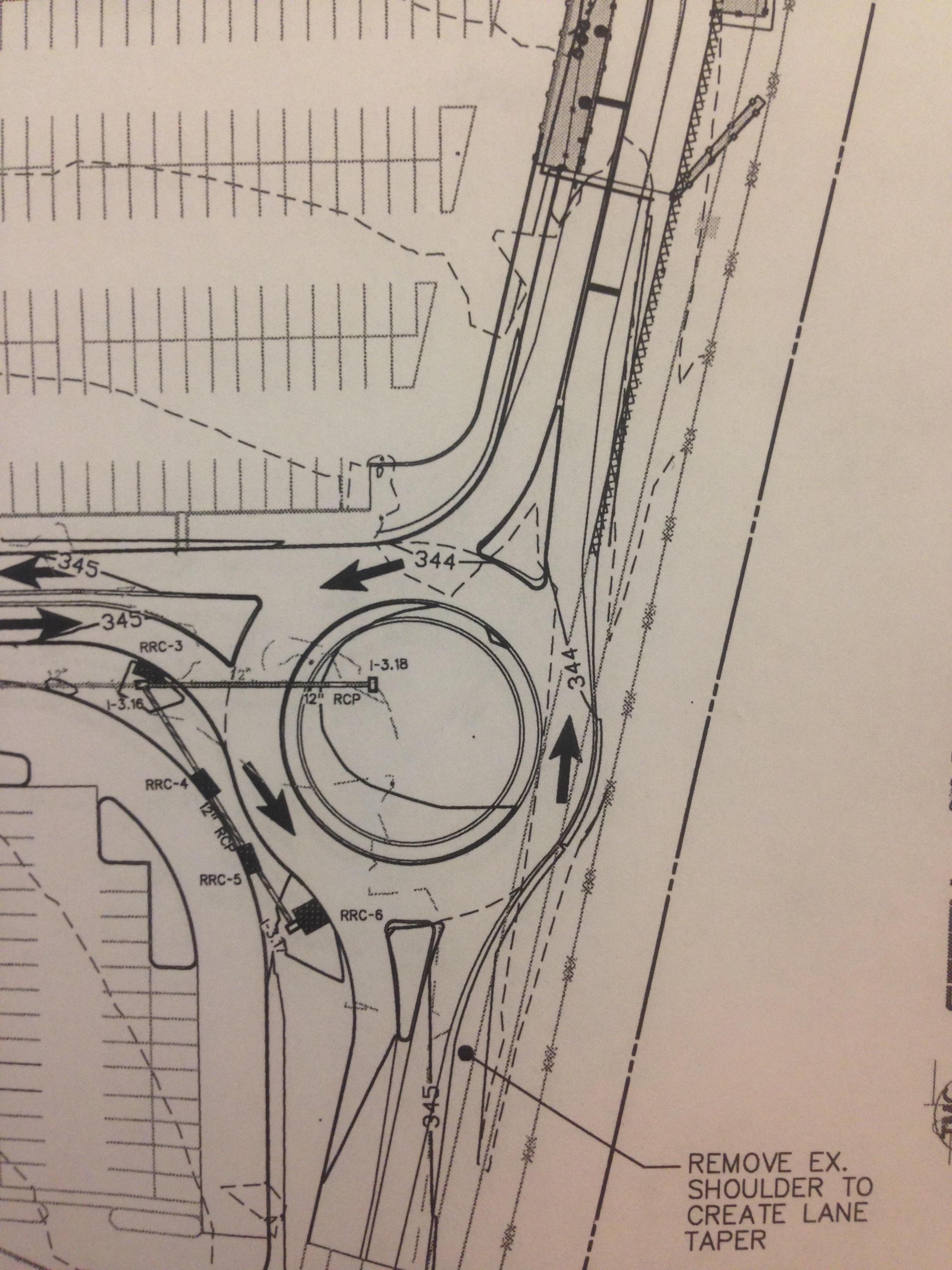
Complete
Finally, to follow on from Damo’s post about cyclist safety:
It doesn’t sound like it will happen any time soon, however it could have huge implications for construction within whatever zone it was implemented. Damo, has the cycle safety scheme on your site been well received?
Levee Inspections
To attempt to take up the mantle from Howard of saving Pennsylvania from catastrophic flooding this week I have been out conducting inspections of elements of the levee network. Every year Baltimore District inspect half of the levees in their AO, which broadly covers Pennsylvania and a section of upstate New York and control flow into the precious Chesapeake.
Sadly my image of Hollywood style concrete channels where we could put the hire car to the test were dashed and replaced by oversized earth berms. I imagine this is the slow time equivalent version of the inspections carried out in six weeks by RE JNCOs in the UK last spring, except completed by two qualified Professional Civil engineers and a couple of hangers on like me.
Below shows a typical levee and our main tasks were to look out for ‘critter’ holes and the wrong type of vegetation. A common occurrence is for groundhogs to burrow completely through the levee, both allowing flow but also destabilising the remainder of the levee. Vegetation is important to promote soil stability but has to be able to bend to the flow to avoid creating an obstruction, or a place for obstructions to settle. Within the main straight channel to the bridge in the distance a meandering path has been engineered for the normal flow condition slowing the flow down, whilst allowing it to drain quickly in a flood condition.
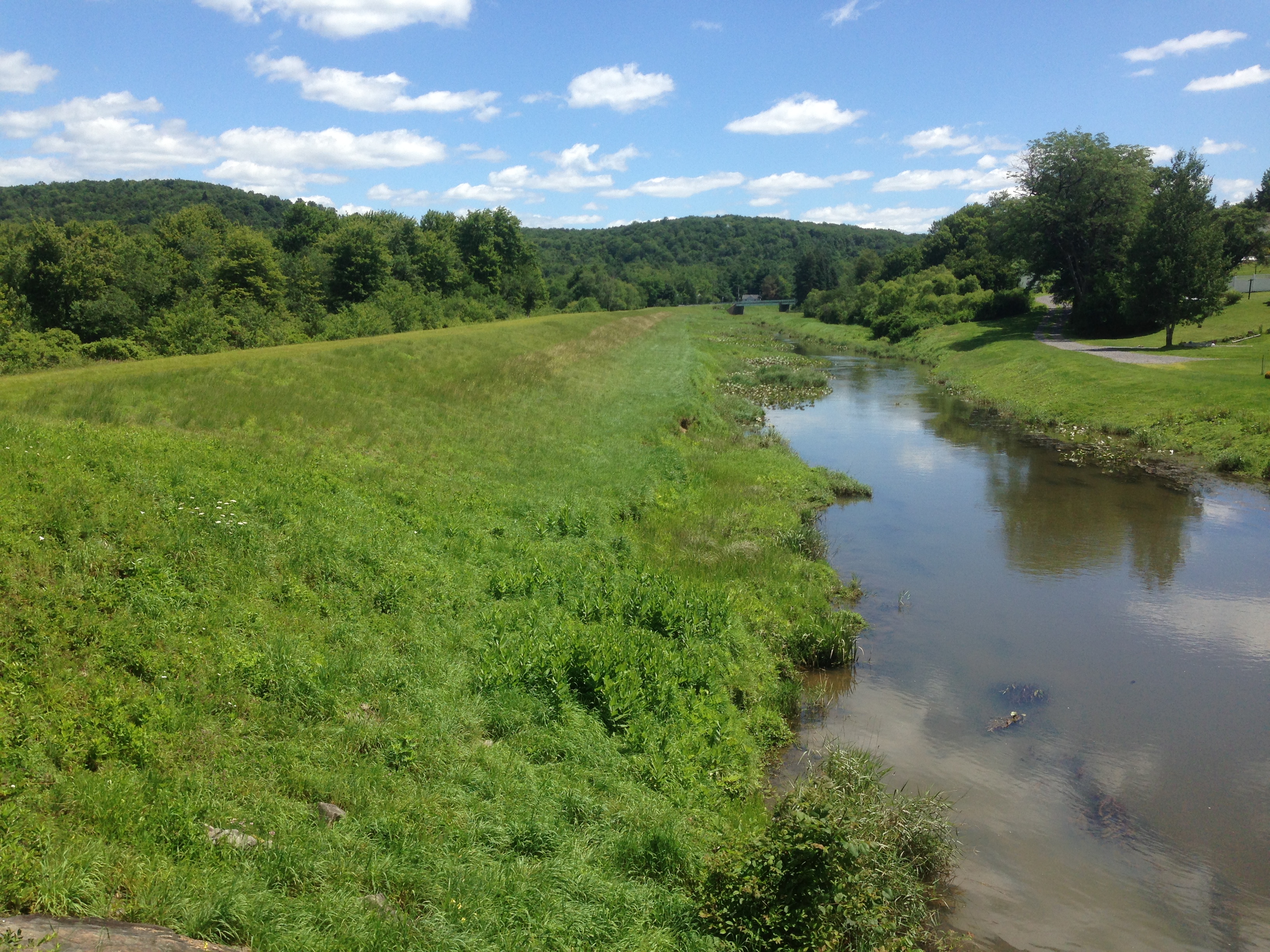
Typical levee and channel
To control flow through the levee from drains gated inlets are used and flap gates prevent back flow from the river up the pipes. These all required checking and had been greased to the standard a farmer would have been proud of.
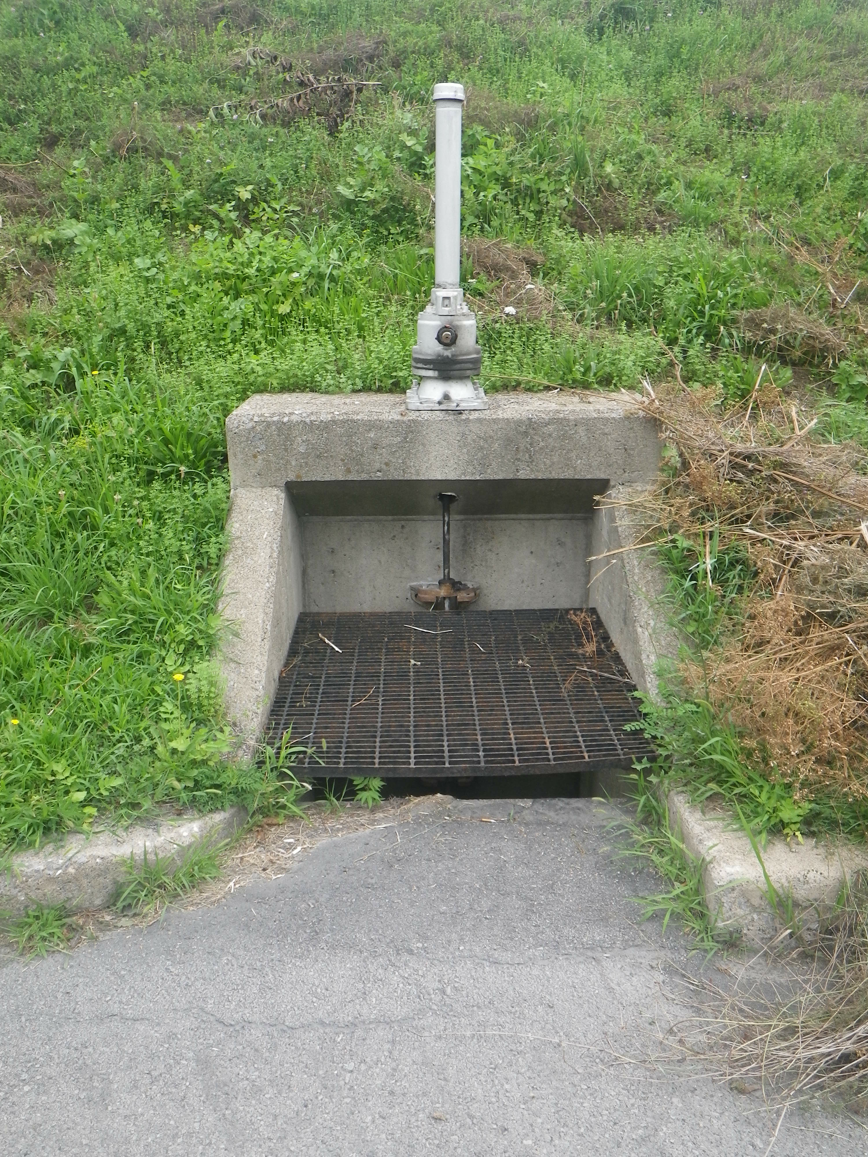
Drain and inlet
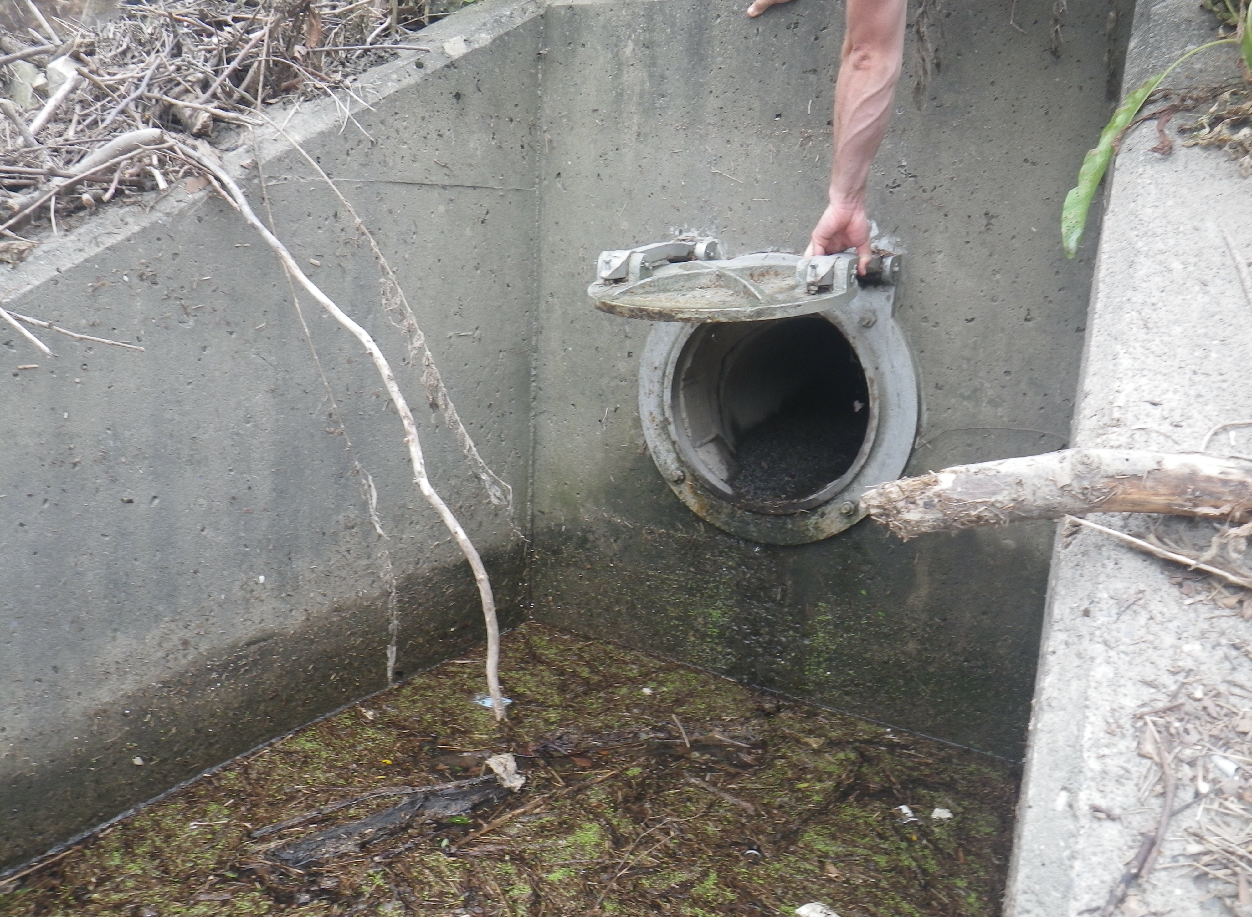
Flapgate outlet, minding out for snakes!
The systems we inspected were built from the 1940s onwards and were simple and robust in their design using, as one would hope, gravity where possible. There were a couple of pump stations with standby generators where gravity had to be overcome. As the drawing shows below a lot of effort is taken to remove the debris and sediment from the flood water to protect the pump and prevent it clogging the pipe work (or pressure conduit to use the vernacular).

Pump station
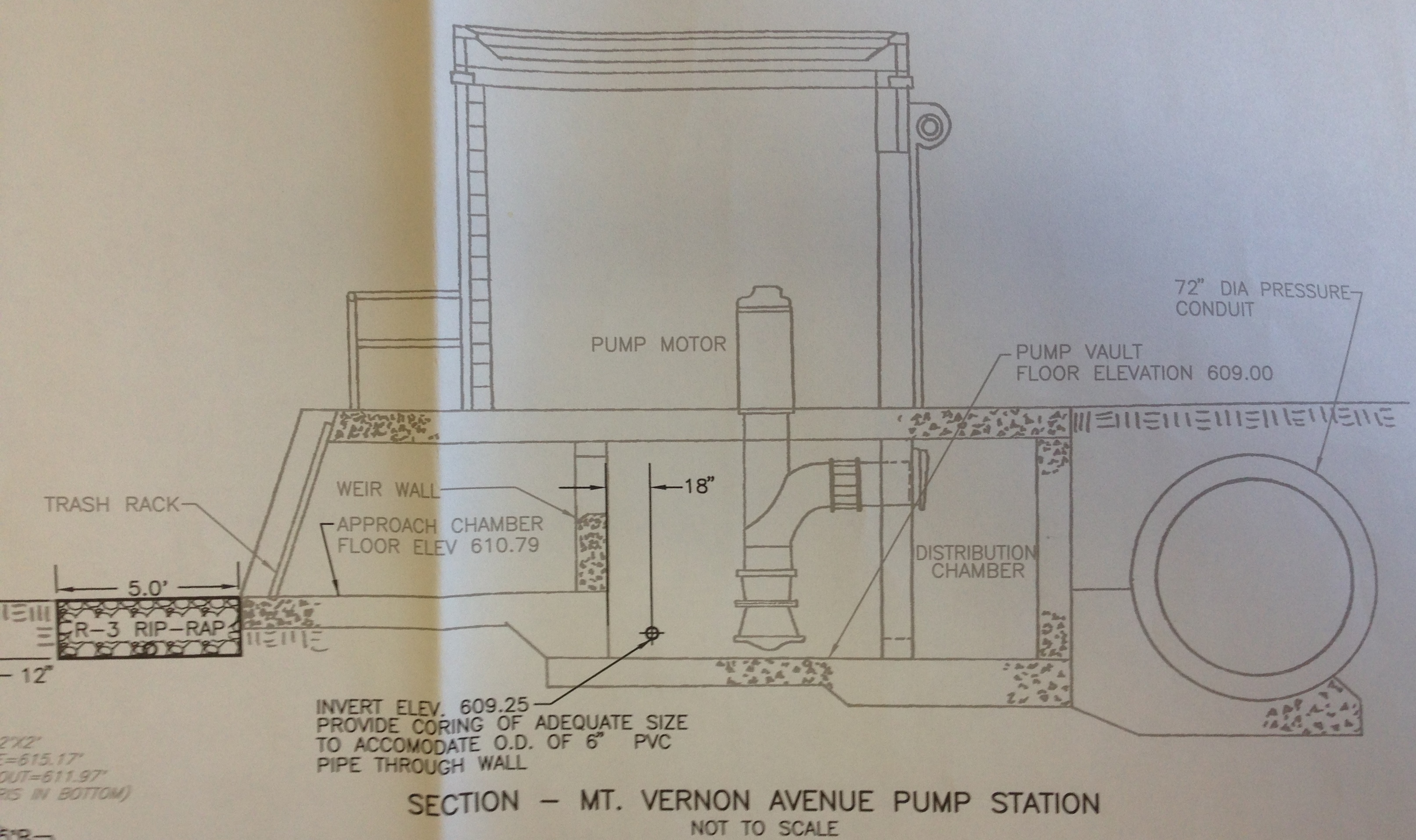
Section through pump station. Water flows L – R
Rip-rap is 6” diameter rough stone.
As far as analysis goes the question in my head this week has been how does it all integrate? My conclusion is that it doesn’t. Responsibility for each levee has been pushed down to the lowest level of government, the Township, and so there doesn’t appear to be an appetite for integration from one to the next. That said, as the map below shows, there is quite a lot of space between townships out here and so maybe that doesn’t matter.
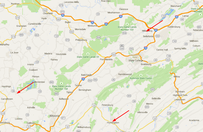
Upstate in Pennsylvania. Huntingdon is 2 hours NW of Harrisburg
I imagine further down stream towards the coast where the population density is higher and all the water converges this would be more of a problem. For now I am going to shelve these thoughts and pick them up again when I get to phase 3, where I can speak to the hydro engineers in their natural environment.
Finally, for the civils who were whinging about making a cofferdam, this is how you do it ‘redneck style!’

Simples!
And apparently this is a salad…

You can just see a piece of salad poking out under the chips and cheese
Bits and Bobs
Things are progressing in the usual manner so I’m going to summarise a few of points of interest from over the last week or so. In no particular order.
- I’ve inherited a Cadet this week. He is an exchange student, currently at the University of North Dakota studying Construction Management. He was essentially dumped in my lap late last week as the Lieutenant who is supposed to be looking after him is out this week. Since I am the only military guy in the office at the moment I went to the airport to pick him up and he is ‘reporting’ to me. Since it was pretty much out of the blue I’ve just been trying to get him inducted, fam’d up on the vehicle fleet, online and then sending him off to the Gym!
- The slides below were presented at a recent talk to the USACE by the Designer of Record (DOR) for one of the projects here. It is a risk assessment tool. I thought I’d stick it up out of interest for everyone to see as it’s something a little different to what I usually see.
Excerpt from DOR presentation. Step 1.
Excerpt from DOR presentation. Stage 2

Excerpt from DOR presentation. Stage 2
Excerpt from DOR presentation. Stage 3
3. There have been a few developments at the Central Utility Plant (CUP). I had an RFI come through about a column mounted Jib crane, which took me by surprise for a few reasons, not least because I didn’t know what a column mounted jib crane was. A quick Google search sorted that out. The next issue; there is nothing in the specs about the crane at all, or anywhere else, other than a note on the contract drawings giving direction about minimum hook heights, weight capacities, conformance to CMAA-70 and a requirement to swing 180 degrees. A cut from the drawing is below:
Excerpt from contract drawings.
Now, Damo has probably noticed that the crane appears to be mounted into the Web of the column; more on this later. Specifically the RFI that I got was to accept a proposed off the shelf solution. It contained some product data and drawings etc and requested that the RFI be sufficient for acceptance without a formal submission. I had a few reservations about this, I had also noticed that the crane appeared to be mounted in the web of the column. And that it appears to be over nothing, even when cross referenced with other drawings. I sent a question to the client asking what the intent of the crane is but have thus far heard nothing. Nobody here seems to know what its for either.
The designer reviewed the RFI and had no issue with the actions that the crane would impose on the column but I still had misgivings, specifically with regards to how the Contractor was intending to mount the crane (welded plate I guess) and maintain the 180 degree reach. I therefore asked for a formal submission with the connection details articulated more clearly than a manufacturers drawing which, in my opinion, won’t work as required. I spoke with the Contracting Officer’s Representative about this because the designer will be able to charge to look through the submission because it will be out-with the originally agreed submission requirements.
4. Specialized (sic) Engineering are the QC sub-contractor that conduct tests such as concrete slump, soil compaction, weld integrity and the like. For my structure they are required to come and check bolt tension, weld and plumb of the building. The most interesting thing, for me, of the last Specialized visit was the apparatus used to test the plumb. The Bazooka bob is an enclosed steel tube with a string tied at one end and measured increments at the other. It extends out and attaches to the steel magnetically. It is 10’-5” with increments of measurement of 1/8th of an inch at the base. A measurement of 2/8” at this distance represents the 1/500 allowable deviation from vertical so if the string falls outside of this you know that the column is deficient. Simples. All the measurements taken on site were within tolerance.
- The cooling towers (a mechanical feature which will eventually sit in the CUP) submission is being bounced around from Principal Contractor to USACE to Client to USACE to… The proposed towers (by the Principal Contractor (PC) were submitted a while ago and returned as deficient with c. 21 comments. The PC re-submitted the same towers with, what I consider, rebuffs to the client comments. I was in a meeting yesterday where the client essentially ‘kicked off’ at the situation questioning why it was that clearly erroneous submissions were being sent in, especially since the crux of the issue is that the cooling towers proposed are so far away from the Basis of Design (BOD). Again the PC had an answer along the lines of “we can ask for a variance to the BOD,” to which the client pretty much said “provide what we ******* ask for in the specs.” Fair enough – it was a heated meeting. This is interesting, not just because of how stubborn the PC is being but also because the cooling towers in the BOD are anchored to the steel building at 12’ centres. The PC preferred towers are anchored to the building at 14’ centres. You can no doubt guess at what spacing the steel frame has been erected, snapped, decked and welded.
- Another BOD issue; I am lead LEED representative at the moment whilst the actual lead LEED lady is on maternity leave. (LEED is essentially the same as BREAM). I have split responsibilities with another guy from the office who is also here temporarily. I reviewed my section (recycled content and regional materials) and had a scan through the rest of the submittal before passing the it to the other guy. I noticed that the PC had made a comment that they were making no effort to submit the 3rd party VOC certification required by the specs for Environmental Air Quality because the material suggested in the BOD didn’t come with it as a matter of course. I gather that they got this information from speaking to the manufacturer named in the BOD. I advised him to ‘E code’ (re-show) the submission and request the PC to send of material to a 3rd party lab for testing and certification. What interested me about this was that the material and manufacturer named in the BOD wasn’t compliant with the specs as a matter of course. I am waiting out to see if the PC gets back to me on this issue or if they will just send the material off for testing. The cooling towers issue hints at the former.
- Another area of contention has been due to backfilling activities (and I mean to echo Guz’s sentiments about good and bad engineers, but also add in ‘Lucky’) For me the issue started when I spotted a sub contractor backfilling some utilities into fairly wet excavations. What didn’t help was that there was water ponding in the weld pits and there was no effort to remove it prior to backfilling. To me this seemed ‘a bit weird’ as a gut reaction although admittedly I wasn’t clued in on the method of backfilling in the specs. I made a call to the PC and said I think the water should be pumped out of the weld pits as a minimum, prior to backfilling, and went to lunch. When I got back from lunch someone from the mechanical team came up and shook my hand for a ‘good catch.’ Apparently what I had witnessed was out of spec (shock) but also another in a long line of deficient practices with respect to the placement of utilities. Whilst I was at lunch the civils project engineer went to have a look at the site, taking along with him 2 other QA reps and some of the mechanical team. The PC superintendent noticed the collection of people and called his QA team . The PC was requested to prove that they had been backfilling properly to which one of their team jumped into the excavation and promptly sank in soil, which was presumably not within 3% of the optimum moisture content called for in the spec. This is an ongoing issue which could well form the basis of a TMR but the point I make here is to echo something I am sure I have heard around PEW but I cant attribute it to anyone in particular; if something doesn’t look right, it probably isn’t. I was fortunate to be passing by the activity when it happened or it mightn’t have been noticed.
In other news: This.

Change!
Since my last blog about the Fort Indiantown Gap progress has been slow. This appears to be as a result of the difficulty from the contractor’s end both in meeting USACE’s various contractual requirements for personnel and an ill defined scope. Following a theme of designers not confirming what is currently in place prior to starting refit designs this had lead to a protracted series of RFIs. Finally to curb this laborious process this week I managed to get everybody into the same room, except for the designer who phoned in, and we managed to thrash through the details.
The issue has come down to the hot water distribution. The original system is shown below at Figure 1 with three separate pumps feeding individual systems. As the H&V unit was removed years ago the demand on P-3 has reduced from 52 to 0.75 Gallons per Minute (GPM). This means it is massively oversized but the designer had just replaced it, he had also labeled it as P-3 on the Boiler Detail (Figure 2) and connected it as if it was a stand-by pump: hence the contractor’s confusion!
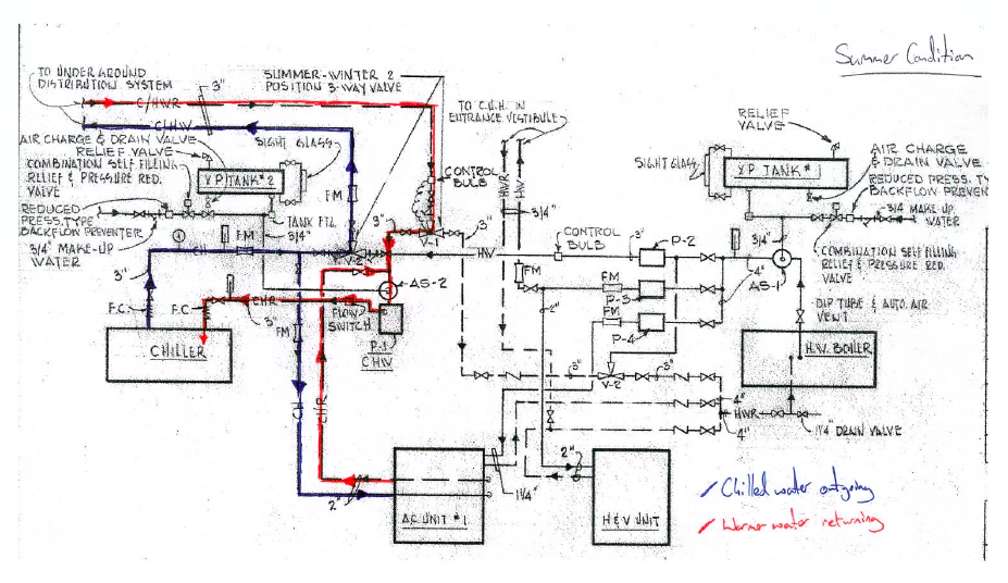
Figure 1: Original System
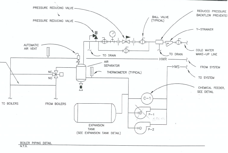
Figure 2: The original replacement design
So as a result of our meeting the contractor and I came up with Figure 3, proof that pen and ink isn’t dead! The other clouds are described below in my contract modification.
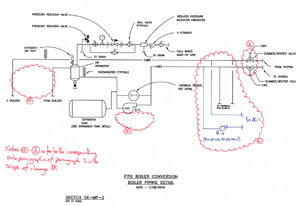
Figure 3: Modification Drawing
‘The boiler piping detail shall be replaced with attached sketch MP-2. This modification includes the following:
a. Removal of the three-way valve (known as V-3) from the hot water return to the boiler as it is not required.
b. Removal of P-1 from the detail. Given that the majority of the load for P-3 (H&V unit that has been removed) no longer exists P-3 shall be removed and the remaining active load added to pump P-2. New total for pump P-2 shall be 111 GPM, the pressure drop will remain as currently scheduled given that the distribution system is the longest run.
c. Hot water piping serving CUH, located in the vestibule, and AC-1 shall be connected to the new hot water piping before the summer/winter change over valve such that it does not receive chilled water from the dual temperature side of the system.
d. Two automatic three-way two position valves are to be included as the summer/winter change over valves. These will switch between the hot water supply and return and the cold water supply and return respectively.’
So what?
This is proof to me that the PEW attachment process works, the original system was not designed to be constructed; instead it was treated as a paperwork exercise. This is probably reminiscent of a few Crosby design exercise submissions, however in my defence there wasn’t a building to walk around and design to.
Another valid idea might have been to increase the size of P-3 and turn it into a stand by pump, however the spare budget for this project is small and needs to be preserved for when problems start occurring in construction so we used the cost saving from this to ‘wash’ against the cost of the automated summer/winter changeover valves. Next stop for this modification is a few stamps from the hierarchy and then into negotiation which should be interesting.
Schedule
Another element of the meeting was to review some of the contractor’s submittals that required changing and this included the project schedule. Fig 4 shows my copy of their schedule prior to the meeting. It is probably difficult to see all the detail but the best part is where the contractor has claimed a value of $120,000 for boiler removal and $45,000 for insulation removal, bearing in mind this is a $500,000 contract. The boiler removal will require skilled personnel and some Materials Handling Equipment (MHE), but the insulation removal will just be Spr Crosby with a knife and a bin; so $4,000 and $1,000 might have been more appropriate. When confronted as to why the project manager, without a hint of shame, said: ‘That’s frontloading.’ I’m not sure whether Steve Payne would be proud or ashamed of him but, needless to say those figures will be adjusted.
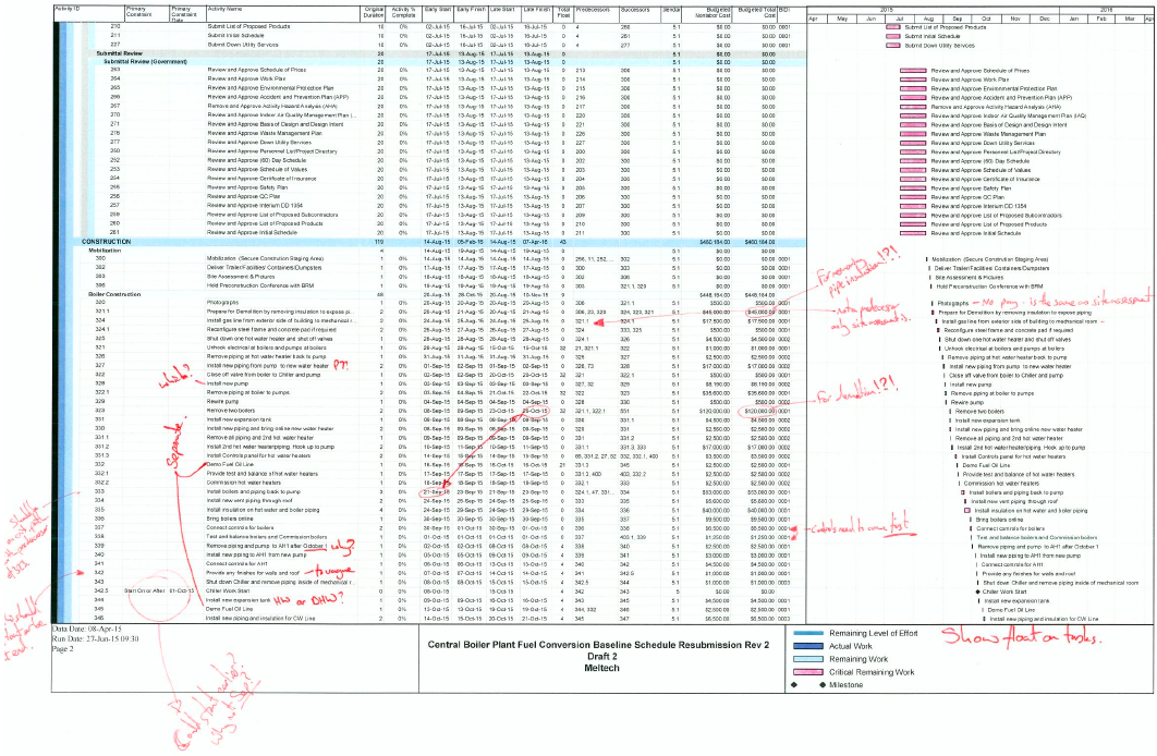
Figure 4: Schedule with my notes.
Looking further into the actual scheduling issues there is little structure which has caused issues. There is a requirement to maintain continuous domestic hot water throughout the project and space is, as ever, tight. It appears to me that no attempt at a Product Breakdown Structure (PBS) and Work Breakdown Structure (WBS) was made which would have aided sequencing of this job.
Signs
The only work that has actually happened on site is the erection of the project signs as shown in figure 5 This also shows a lamppost, and a High Voltage (HV) Ring Main Unit in the background. The consequence of locating the project sign so close to the lamppost and HV Ring Main Unit could have resulted in death as a result of cable strike when digging the postholes. Fortunately, no one was injured in the erection of the sign. As well as the potential outcome for the contractor’s employee erecting the sign, contractor has also not asked for permission to dig. Therefore I took the action of writing a warning letter in order to warn the contractor’s senior management of the error. Also, as this was the first actual work on site, the letter catalogues the error so that, in case further H&S violations are witnessed, there is evidence to remove them from the site.
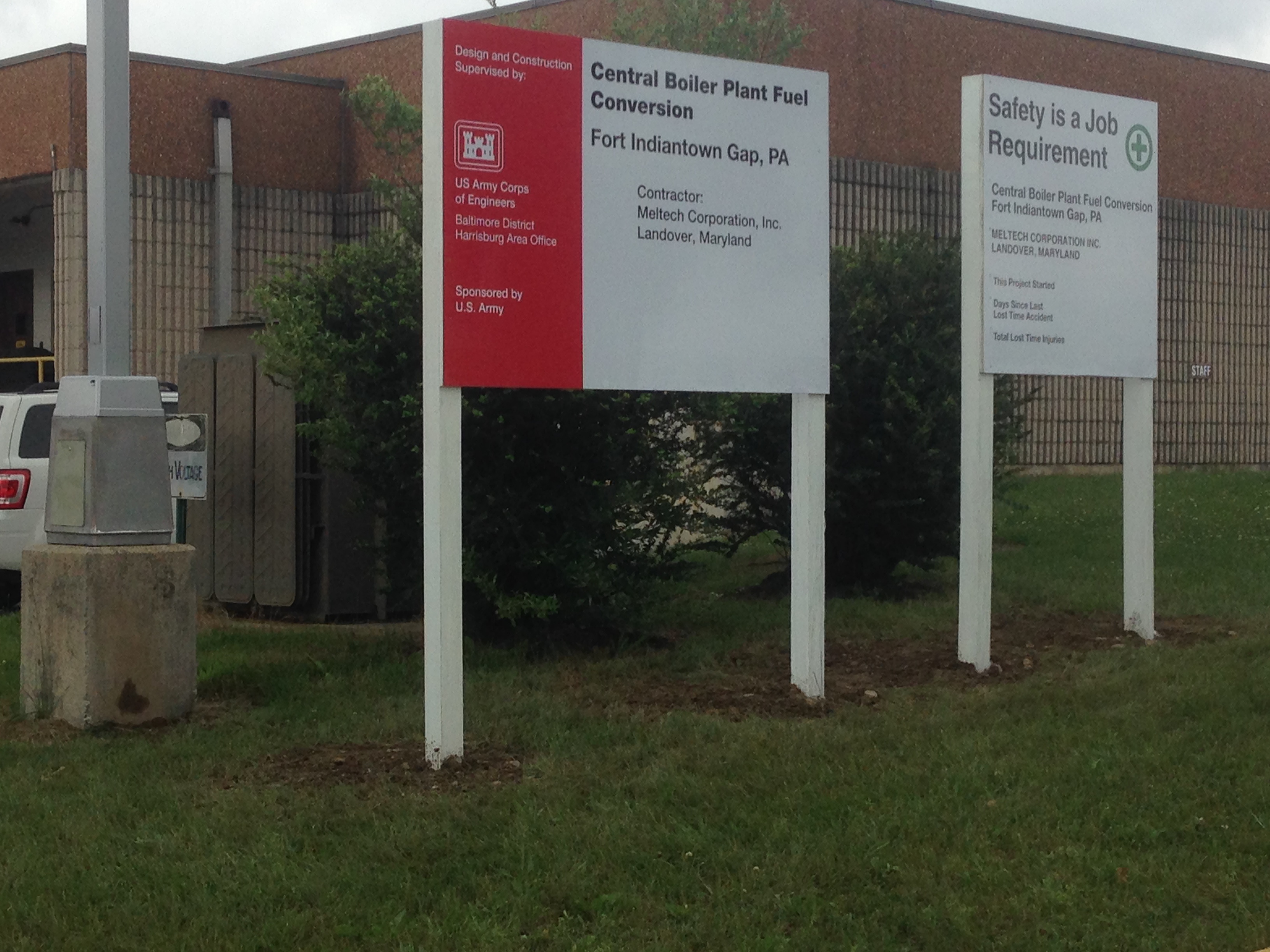
Figure 5: Spot the H&S risks!
Illegal Steel Erection
Firstly – Nice job Guz, Swimmer and Fat-Bloke.
The Coffee CUP is nearing completion of sequence 1 / 4 structurally. In the main things have progressed smoothly, with the odd schnell evacuation due to the recent thunderstorms. Minor glitches include the incorrect placement of anchor rod bolts which attach the baseplates of the columns to the rc pad foundations. This was a quick fix with the erroneous bolts cut down to the profile of the bottom of the base plate (essentially so the base plate was resting on top of the cut down bolts) and new HILTI bolts epoxied into newly drilled holes in the correct location.
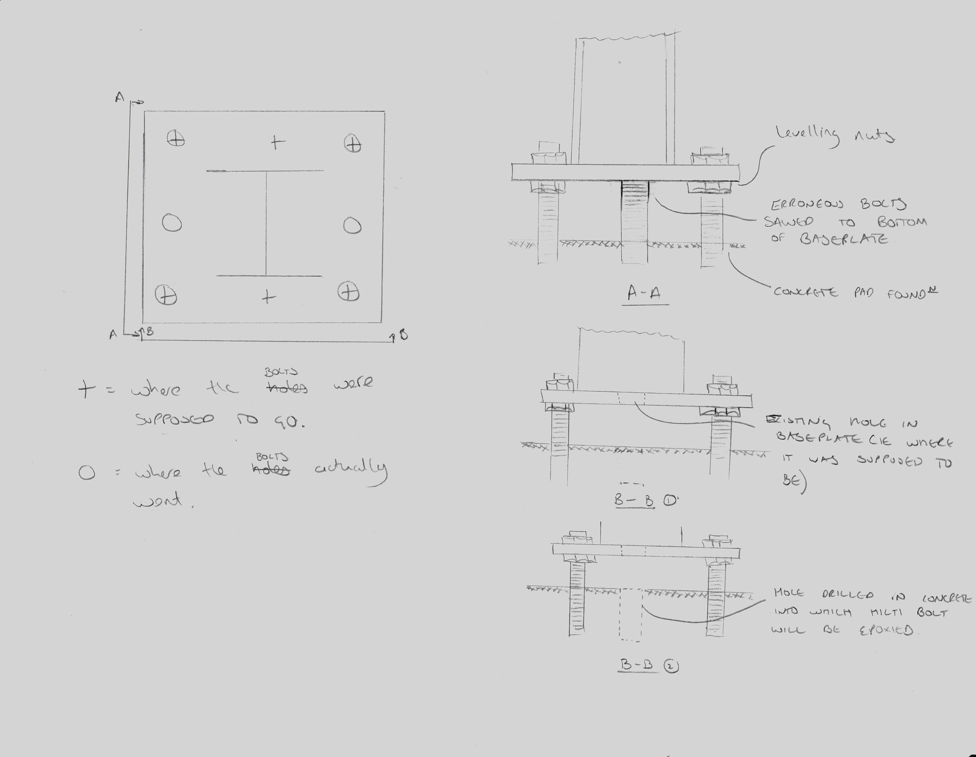
Sketch of Baseplate anchor rod correction
The washers used at the base plate location also need replacing with larger ones so that they entirely cover the drilled holes in the base plate. This will allow any uplift forces to be properly distributed to the baseplate through the entirety of the washer.
A more serious problem arose at the placement of a double bolted connection. A double bolted connection is essentially a shared connection between two beams on opposite sides of a single column. This is a fairly common connection type however the method of erection is supposed to be controlled for safety reasons. This is stated by the Occupational Safety and Health Administration (OSHA) para 1926.756 and also in the USACE HQ document EM385-1-1 at OSHA and EM385-1-1 (Cl 27 E)
Erection in a manner contrary to these documents is essentially illegal so in order to prevent the issue correct erection methods are stipulated in the contract documentation (spec) and checked for in the steel erection plan submittal which is required by the government before work can start. In cases where shared connections exist there are three standard ways of staying compliant with the regulations. These are sketched (crudely) below but are 1. Cut outs in the end plate. 2. Staggered end plates. 3. Welded or bolted shop or field attached seats. These methods are designed to either support the first beam directly or by allowing the minimum single snug type nut and bolt to remain in place whilst the second beam is flown into position. This removes the risk of the first beam slipping its connection and falling during the process.
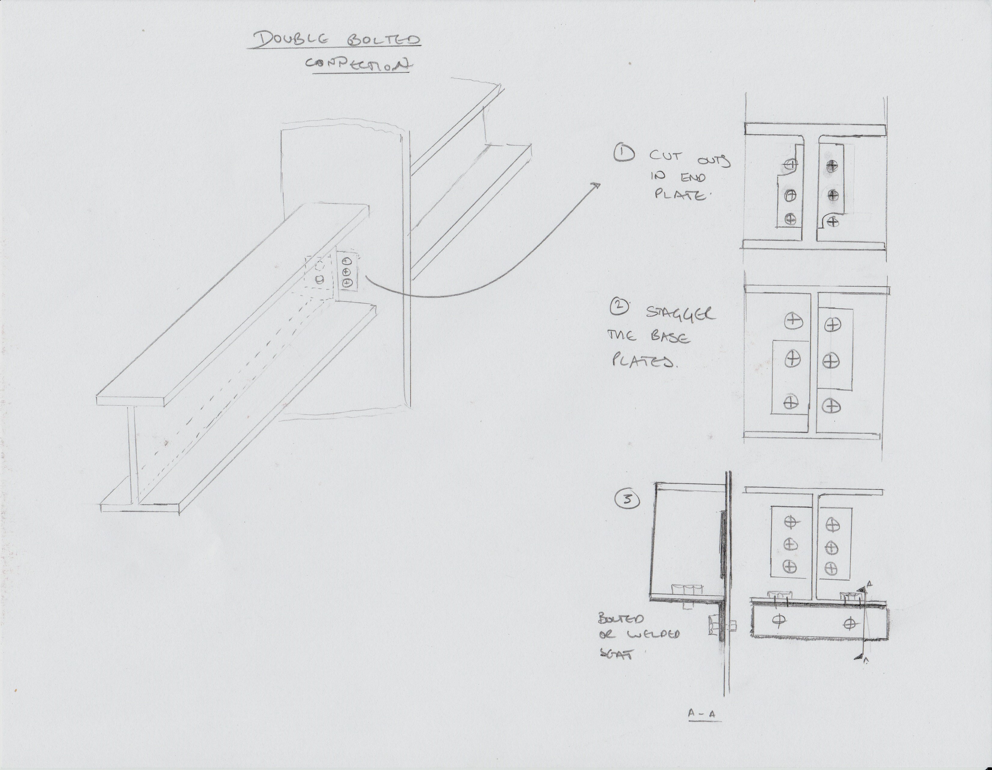
3 methods of fabricating for double connections
On site the majority of the shared connections are staggered (pic 2) to allow for this method of erection, however some have neither a cut out in the end plate or staggered base plates. When asked exactly how he had placed the beams the subbie admitted that he had removed the nut which had been placed after the first beam had been flown in and one of his lads had stuck his spud wrench through one of the other bolt holes. Highly naughty. We chatted about the situation for a while and figured that there must have been some sort of detailing error because it made no sense to not stagger the connection plates, and even less to not detail a factory fitted seat. Since he was the sub contractor I am not supposed to give him direction, unless it is an imminent safety issue, so I had to speak with my counterpart at the Principal Contractor in order to resolve the issue.
I went back to the office and was able to corner the resident steel expert who pointed me to the US American Welding Society document D1.1. This thrilling tome has within its many many pages a calculation for the strength of a fillet weld which is basically a function of the area of the weld and the grade of steel of the rod that is used during welding, with a factor of safety thrown in. I was able to assess from the field drawings what the heaviest beam would be in the whole construction and based my calculations on this. I proposed a 1” x ¼ “ fillet weld which could be applied in the field to the first beam that was flown in. This would be more than sufficient to hold the beam in place whilst the nut was removed in order to fly in the second beam. Obviously my proposal was only a recommendation and the actual design would need to come from the Principal Contractor. I highlighted this to them and requested that they submit an RFI for the field solution so that an audit trail would exist.
My proposal was questioned with an air of refusal by my counterpart who said that she had spoken to her manager who didn’t see the problem. A quick scan through the necessary paperwork, including EM385, the Specs and the Steel Erection Plan and a face to face with some relevant paragraphs printed out highlighted the government’s position. The issue remains unresolved as we wait for the RFI but the last I heard the Health and Safety guy had waded in and written a deficiency. This takes the issue in a more ‘formal’ direction which I had been trying to avoid.
Incidentally – I tried to find a similar clause in CDM but didn’t get on so well. Does anybody else know if there is one / where it is?
In other news – my wife and I went on a road trip to Niagara falls. Wetter than an otters pocket.

I also navigated one of the more arduous ‘trails’ in typical local attire fuelled by suitable amounts of coffee.

Standard US hiking Garb
US Measurement system
My biggest fear coming out here on attachment was the measurement system, besides people with guns and the MVA. It is essentially an archaic foreign language with little real utility in the modern metric world; a little like Gaelic. The best way to deal with issues like this is obviously to avoid them that is a little difficult here so I’ve had to just roll with it and enjoy the chaos.
This blog is not meant to be a definitive list of all forms of measurement, for that there is Wikipedia, rather a quick run down of the ones I’ve come across to help anyone coming out here on attachment in the future and also anyone that finds themselves in the economic shadow of the USA. Places, as Nick West has found out, like Montserrat use the US measurement system because the US is their chief supplier.
A few things to note are: firstly, the US measurement system is that it is not the same as British Imperial measurement. It’s mainly the same but not always, so beware! Secondly, the descriptions of how they came about are entirely logical as a unit of measure from when they were thought up. They just don’t really combine together quite as well as metric when combined and some funky factors start coming out. The big danger in trying to convert backwards and forwards is that calculator errors start to add up and cause issues with suppliers trying to over charge you for ‘non standard’ items.
The simple ones:
Feet (ft or ‘) and inches (in or “): Simple stuff, 12 inches to a foot, 3 feet to a yard. When you start to go smaller than an inch fractions are often used. On drawings the rough rules are: less than 2’ all measurements will be in inches only, after that feet and inches are mixed.
Pounds (lbs): 0.454kg. Straightforward, there is no use of the stone, but the hundredweight is used which is, as one might imagine, 100lb or 45.4kg.
Liquid Measure: Mainly for cooking and fuel to be honest but kids are taught: ‘two cups to the pint, two pints to the quart, four quarts to the gallon.’ Key points to remember here are that both the pint and gallon are smaller in the US than in the UK. That means that the people are less accomplished drinkers and that cars seem less efficient (not the only reason they seem less efficient!). A US gallon is 3.79l and a pint is 473ml.
Fahrenheit (F): The weather is as much a topic of idle conversation as it is in the UK. The difference being that out here it swings wildly across the seasons but the conversion is pretty straightforward. Fahrenheit = 1.8xCelsius + 32.
Where it starts getting interesting:
CFM because it takes too long to say cubic feet per minute is used for airflow in ventilation systems. 1m3s-1 is 2119fcm; which is close enough to 2000 for mental arithmetic.
PSI is pounds per square inch, which we are used to for car tyres etc. When speaking about gauge pressure it must be remembered to add 14.6 psi for atmospheric pressure to get the absolute pressure.
And onto my favourites:
BTU stands for British Thermal Unit, which I have personally taken the blame for on a number of occasions already. For dinner parties it is the energy required to heat one pound of water by one Fahrenheit. It is equivalent to 1055 Joules, fortunately close to 1kJoule!
Ton. Also called a ‘ton of refrigeration’ this is the heat absorbed by melting a short ton of pure ice at 32F in 24 hours. Out here it seems to be exclusively used for large chillers in HVAC units but is equivalent to 3.5kW.
Footcandle (fc). This is a measure of illuminance and is simply the light given out by a candle at a foot. This shows the weakness of the customary units as illuminance should be measured as luminous intensity per unit area. Fortunately its difficult to measure this with any more than10% accuracy and 1 fc is 10.7lux so close enough to 10 for measurement.
So that’s ‘how for now’. I assume some imperial units are still used by the old and bold out on site in the UK as that’s how people learnt their trades. What is it like in Australia? I’m sure Howard and Brad will have seen some pretty funky civil units! Please feel free to add any more in the comments section that people have seen. I will try to keep this up to date more as I go through the attachment.
Fort Indiantown Gap
Fort Indiantown Gap (FtIG) is a U.S. Army post primarily used as the Pennsylvania National Guard Headquarters and main training facility about 25 miles North East of Harrisburg. It is also the location of another project I am involved in/running.
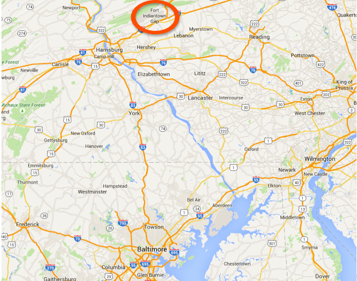
Map showing Fort Indiantown Gap
As part of America’s war on greenhouse gas emissions, or perhaps their fear of other people controlling energy resources, FtIG is converting from a reliance on oil to natural gas as it’s main form of heating energy. This is in common with a lot of other Department of Defense (DoD) sites and is as a result of an executive order issued by the great environmentalist George Bush. From this two questions should spring to mind; the first of which being how old is the executive order, well it’s from 2007. The second possibly has more to do with George Bush’s politics and for that discussion I will have to refer you to the kebab shop in Kingston upon Thames.
Either way, as a result one of the boiler rooms at FtIG requires a replacement of its 2 x heating boilers, domestic hot water boiler, their pumps and most of the pipework within the plant room as well as cleaning the chiller pipework. The existing system was installed in 1975 and has been somewhat tampered with, although not completely refitted it appears so, with a 15 year design life, is on its last legs. Below the diagram shows the as built drawings of the heating and chilled water systems with my annotations for the summer and winter conditions:
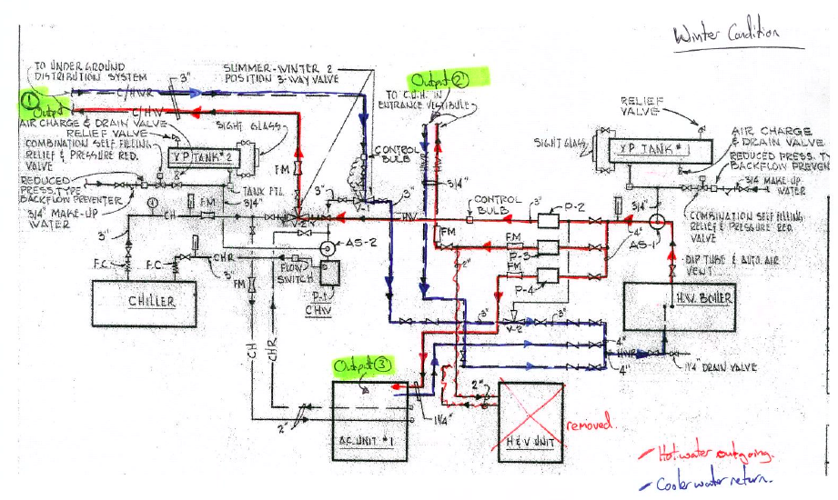
Winter Condition
These systems have three outputs, as shown in the winter condition: firstly to the underground pipe network feeding the Variable Air Volume (VAV) terminals in the building with either hot or cold water depending on the season. Secondly, due to the removal of the Heating and Ventilation (H&V) Unit (bottom right) a single unit heater is supplied and thirdly the air conditioning unit within the plant room which supplies ducted air into the building. What is significant about this system is mainly that the first output consists of a single, two pipe system supplying either hot or chilled water. Therefore in the seasons of spring and autumn when the requirement of the system is likely to vary between heating and cooling throughout the course of a day the system will have to cool the water within the pipework before having any effect on the building.
So are we going to fix that, hell no! Currently the design is merely to replace like for like despite there being a reasonably simple solution. This appears to be due to the ’colour of the money’. The money funding this project is only supposed to fund improvements in efficiency rather than improvements in performance.
To see what the actual cost would be I decided to do a calculation, so assuming the 3” pipe is 1km long, the water is of density 1000kg/m3 and would have to be cooled from 80°C to 10°C.
Water Volume in pipes: V=length x π r2 = 1000 x π 0.03752 = 4.42m3
Water Mass in pipes: m = ρV = 1000 x 4.42 = 4420kg
Heat loss required: Q = mCΔT = 4420 x 4.18 x(80 – 10) = 1293MJ
Converted to kWh as that is what electricity is billed in: 1293000/3600 = 359kWh
Assuming the fort pays the same as I do per kWh the cost is 13c/kWh, therefore:
0.13 x 359 = $46.72 per time the system is cooled down. So if this occurs 30 times during each spring and the same each autumn, that is 60 occurrences per year, costing $2,803.
Whilst in ‘calculation mode’ I thought it worth looking at the time it would take to cool the loop down to determine the response of the system. So assuming a 60 ton chiller (from a combination of the drawings and a SWAG):
Power in KW = 3.5 x Power in tons = 3.5 x 60 = 210kW
t = Q/P = 1293000/210 = 6,161s or 1:43
So at the point that the system determines to go from heating to cooling it will take nearly 2 hours for the system to start to have an effect, not ideal on a hot spring day. In payback period terms it is probably in the same region as Mike’s windows. However, like Mike’s windows the system will probably be in position for long past that time period and in the mean time it will produce an enhanced product and save the environment a little, which would surely be good enough reasons on their own. So what, well it seems like a sensible idea to me but I imagine the issue of the funding will be what prevents a logical decision being made. Sadly if we don’t implement something it will be a kick in the teeth for me on competence E3 but hopefully my case here is an element of evidence enough for that!
In other news Jo is now the proud owner of a Maryland State drivers licence. Her test consisted of backing into a parking bay followed by a short cruise around the block completing both left and right turns at four way stops. No traffic lights and she didn’t get above 25mph. Jo was expecting to have to parallel park the car at some point but apparently that was taken out of the test last week because too many people were failing; words fail me!
The Splice of Life
Work continues on site at a fairly decent pace and there is much focus on the project interfaces especially now that the Notice to Proceed (NTP) has been given to the third project on the site. There is talk at present about the selected construction methods for the project I am working on with regards to the erection of the structural steelwork. This will form a part of the central atrium and will ultimately be the architectural feature of the whole building. At present the proposal is that as the steel columns are placed they will be tied from the outside of the building until the relevant roof truss section is placed and the element of the frame becomes self supporting. However due to delays on the adjacent project and subsequent efforts to make up the time they now require the space where the ties were supposed to go. This means that either 1. The ‘ties on the outside’ idea will now have to become a ‘struts on the inside’ idea to accommodate work on the façade of the adjacent project. 2. Shift work. This is still very much a work in progress.
Away from the structural steel side of life a recent check on one of the columns revealed that the lap length was insufficient. Initially this was spotted by comparison to the contract drawings, which have a little table showing the required lengths based on steel type (60,000psi or 75,000psi) and diameter. This makes QC fairly easy. The specified length was 63” however only 54” was measured. The root cause of the issue was a sequencing error on the part of the contractor.
The column in question was a central column which had tie in to two elevated two way slabs at differing levels and the RC beam which forms a part of the monolithic frame of the building. This means lots of steel. The general idea can be seen in the diagram below – which is a general detail with the column rebar drawn in red for clarity. DEFINITELY NTS!
As you can see the lap measurement is intended to be from the base of the lower slab. Because of the ATFP requirements and the amount of steel required in the beams my suggested sequence would be to place the steel cage for the column and construct the beam through it. In this case however the steel for the beam was placed, and then poured with starter bars left protruding for the column cage to tie in with. This reduced length is obviously insufficient and outwith the specification.
The error was immediately highlighted to the Principal and sub- contractor who were informed that they couldn’t close up the formwork and must put a hold on the following day’s pour. This obviously meant knock on delays to follow on slab pours. The only way forwards that I could see was to strip out the pour and start again, at huge cost in time and money or to lengthen the bars by welding, couplers or some other suitable method. I spoke with one of the other Project Engineer on site who checked the measurement and agreed that the error was too far out and we discussed a way forwards to try to minimize the delay. We looked at the lap length specified and he suggested looking to the Codes for a way out – specifically ACI318-11 which is the US version of the BS EN1992:1-1:2004. I broke out into somewhat of a cold sweat at the suggestion and was just about to propose ironing certain parts of my anatomy as an alternative but when he started to take me through the codes and to the relevant section on ‘splices’ I noticed that the code seemed somewhat user friendly – it even has a commentary section.
Excerpt from ACI 318
There is still the whole Eurocode-esque requirement to flick back and forth between referenced clauses, however in the e-version of the document these references are hyperlinked, so switching back and forth between clauses is somewhat less of a naus than the frantic wheel scrolling endured on the design exercises. Anyway – the calculation for the splice length is quite simple, just 1.3 x the calculated development length because this sort of splice is a Class ‘B’. In true Code style though, the development length calculation was almost an impenetrable mash of greek symbols.
The commentary provided useful direction and actually most of the factors are taken as 1. So it can be seen that the development length is actually a product of Fy, Fc and bar diameter. In this case though I knew what the actual length was; I knew what strength steel we had and the bar diameter and so I adjusted the strength of the concrete until the calculated length matched the measured. This solution was acceptable, just about, based on restrictions in the design code about the acceptable strengths of concrete that could be used. It was calculated that a 10,000 psi instead of the 60,000 specified concrete would suffice. The proposal was obviously sent to the designer for their approval, which came back fairly promptly to proceed with the higher strength concrete. In the end the pour was only delayed by around two days, and now there are some super strength columns in the structure so everyone was fairly happy.
In other news we have a birds nest in our garden which has become the focus of some evening entertainment. So far the attrition rate of the chicks is around 50%. We are not sure if the two that we found lying dead on our patio were pushed by the other two, or if they just fell but at present king of the ring is a fairly brutal affair. Also, me and Danielle went to the tallest waterfall in Maryland.