Any takers? Assistance much appreciated. There is no prize!!!!
Situation
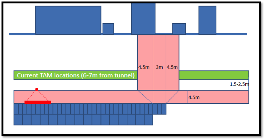
Have a look at the sketch below. As the tunnel is being excavated, above the tunnel there is a ‘umbrella’ of grouting (this is constructed using TAM’s, Tube A Manchette). The grouting is there to mitigate the settlement on the surface. However there are no grouting zone, that ensures the pressure from the grouting does not effect the exposed face (in this case 3 rings, 3m). The horizontal no grouting zone runs parallel to the tunnel at a depth of 4.5m, the vertical zone moves with the construction, however it’s dimensions are dictated by the exposed face (3m) and the angle that the TAM pressure influences (currently at 45 deg)
Issue
The problem is that the amber trigger levels have been hit, ref the surface settlement. The subcontractor want us to reduce the vertical ‘no grouting’ zone. This can only be achieved by reducing the angle from 45 deg to say 30 deg as the exposed face can not be reduced.
Calcs
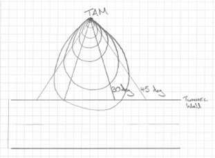
If the pressure on the face is approximated as conical spread from point of injection. My preliminary calcs suggest that a reduction from 45 deg to 30 deg will impose a 300% increase in the pressure, as the area will reduce from 61m2 to 20m2.
However this is a very rough approximation, as many of the stress counters from the TAM will be contained within the 30 deg. What Im trying to calculate is the % of stress that will be contained within the 30 deg compared to the 45 deg. Does this make sense? How the hell can I do it?

Unfortunately it doesn’t make sense to me. I have tried to understand, honestly I have, but to no avail. I am OK with the concept of TAM grouting (it is usually not a point application because of the ‘perforated tube’ legth etc) I can understand the face loss settlement issue. I can just about understand the no grouting zones but there I lose it. 1) Where is the grout being delivered? From the surface? from the face of the excavation? A point some distance back from the face? 2) Is the grouting completed in advance of excavation or afterwards as an attempted loss replacement measure? 3) Why are you presuming a presure bulb of the shape you indicate? and finally, is it defintiely an issue with the grouting that is causing to the settlement?
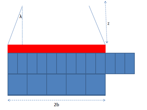
The grout is installed prior to the tunnel excavation, in order to stop the settlement. As a result it is not a loss replacement method. Otherwise the damage to the surface structures would have all ready occurred. The grouting is done from a number of grout shafts scattered around the tunnel envelope, some of the grout shafts are 60m from the delivery of the grout. I am modelling the pressure as a conical zone, radiating out from the point of injection. Although the TAM is a perforated tube, there are specific points that inject the grout. It is at this single point that I am modelling. I think my best bet is to use the Boussinesq theory, which I’m trying at the moment.
OK,
1) Just to irritate JM: The process is intended to hold the ground above whilst you dig out a hole and line it. If you don’t then fill in the gap between the lining and the hole the ground above will eventually settle down onto your lining. This loss will occur no matter how close to the face of excavation you manage to grout. If the loss is instantaneous then your grouting isn’t working. This ‘might’ be improved by more grouting and grouting closer to the excavation face. Your subcontractor is assuming the latter situation to be the case. Lets presume for the moment that he’s right.
2) You want to grout closer to the face of the excavation. You are injecting grout at a point source 6-7m above the line of the tunnel at a distance horizontally from the face of excavation of 3m + a projection at 45 degrees? This is at odds with your diagram which shows an upwards off set of 4.5m but horizontal of 2.5m which is 29 degrees! I do not understand the geometry – can you explain?
3) I don’t think that a bousinesque pressure bulb is appropriate because a point source will give radial pressure (save for anisotropic ground effects, ground water influence, pressure head and numerous other trivial factors!). there is not a vertically applied force beneath a constraining base(boundary condition).
Well I’m not sure
I would guess that the unberella is injet a litte ahead of the tunnel?
This would mean that the TAMS injec tas close to the moveing face (so just outside the pink ‘ no grout’ zone – yes the dims are a pit to cock)
I don’t get the conical model at all
Let’s say you inject at a point source, then an isotropic total stress is increased; The toal stress change ( in any direction) can be estimated using (as you rightly pioint out) Boussinesq BUT heavily modified because
a) the load is applied within the (assumed elastic medium)
b) direction of total stress that you are interested as ( you say the ‘face’ by which I assume you mean the tunnelling face)
A book known as ‘Poulos and Davis’ something like Elastic Solutions in Soil and Rock Mechanics’ is your best bet…. that or FE modelling
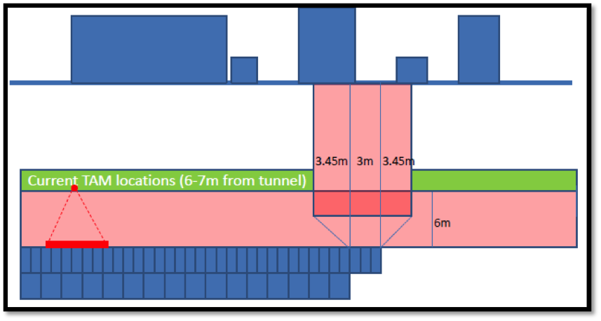
Hopefully the new diagrams will clarify the situation.
Mike
I’ll leave it to John. …..but I must admit that I cannot understand your drawings – some labels would help here
Regards
Neil