Archive
Its the root of all evil in my book.
It seems like the last few weeks have been dominated by finance. Despite the fact that the Minox B Blower is now in offshore execute, my attention has been largely drawn into money matters surrounding my other projects. Minox is going well incidentally and, despite the work site being almost 300 miles away, I feel like I know what is going on…touch wood.
My money matters all seem to have come to a head at the same time, which is handy in a way, but is also a pain in the bum to a degree. My largest scope of work is a DSP that I have been writing over the last few months that argues for the reduction of a £25m engineering programme down to the size of a £5m engineering project. I have traction with all of the stakeholders and am on the verge of releasing the DSP into the wild, after that I will run a gate meeting with the stakeholders to confirm their buy in and then get them to sign on the dotted line. This has been a fairly epic piece of work that I picked up in the summer last year, pretty much the first job I worked on, so it will be great to see it come to fruition. The DSP is around 5000 words all told and with appendices is about 120 pages…not that word counts are important or anything “ahem”.
The biggest issue I have had is the continuation of the Clair Coolers project which, for one reason or another (maybe another time for this explanation), has blown through the agreed budget of £6.7m but only completed three quarters of the original scope. I hasten to add that I am not responsible for any of this overspend, but I am responsible for securing the £1.8m required to get the project back on track. Work continues, but we are on dicy ground until my new funding comes in. I am now at the stage where my Financial Memoranda has been reviewed and is pending release to the VP operations and the the big dog Trevor Garlick.
On a much smaller scale, the issue I was having last month with temperature transmitters is still ongoing. This debacle has identified that the purchase order covering the work has been closed, so I have had to work with WGPSN to deliver a new estimate for the remaining work in the project and get a new purchase order set up. These are just delays which take me closer to the 12w gate without having a rock solid work scope. I am not convinced that this project will stay in the plan at this point.
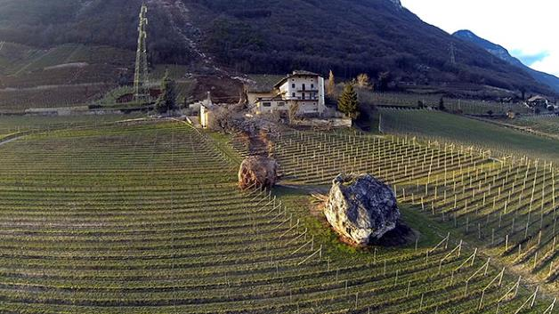
Away from the financial stuff, last week I got off to Germany to visit the fabricator Hans Leffer. These guys fabricate pressure vessels and proprietary drilling and piling technology amongst other things. It was a fantastic trip, the workshop is the size of three football pitches with a huge variety of equipment for rolling, forming, welding etc a similarly large variety of materials. While I was not allowed to actually do any welding, apparantly it is really highly skilled work and 6″ thick titanium block is really expensive, I had a good nose around. Sadly due to the comercial nature of the work, I’ve only got stock photos at this stage, but it gives a good idea.
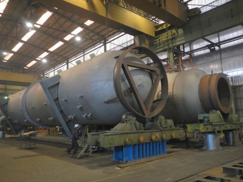
Pressure vessels at the Leffer works
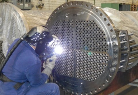
Tube sheet welding on an STHX (not me!)
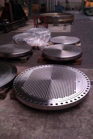
Some really big bits of titanium
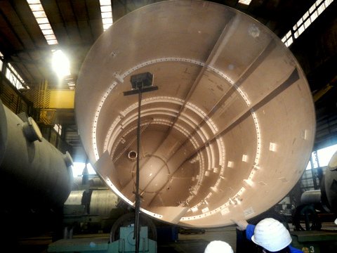
The inside of a medium sized separator vessel
The trip built into my thesis work well as I am analysing the performance of the heat exchangers they supplied to BP last year. It also showed me how the other half live, fancy hotel and hosted the whole time by Hans Leffer himself. I am not looking forward to a return to the frugalities of JPA!
The thesis is going well at the moment, but these posts are likely to be few and far between for the forseeable future. There just isn’t enough time in the day and something has to give!
In other news:
Corine is getting really big now with only about 6 weeks to go. The race is on to complete the thesis before trouble arrives! The Scottish weather is lovely at the moment, wall to wall rain and sleet. I tell a lie, we did have one sunny day last wee and we got out of the house for a bit, but it really is quite dreech at the moment. On the plus side it is now light in the mornings again!
And some Dilbert!

Blog time.
Graham Construction are currently undertaking the design and construction of a renewable fuels terminal for Associated British Ports’ (ABP) in sunny Immingham. The port facility will give ABP the capability to import, store and onward transfer wood pellets primarily to the Selby based Drax power station , as they transform 3 of their 6 coal-fired power generating units to biomass fuelled units.
Once completed, the 11.5-acre facility will be a fully automated bulk-handling terminal that will handle biomass for the region’s power generating industry. The terminal will have the capability of handling around three million tonnes each year, and be able to store up to 100,000 tonnes of wood pellets. Four storage silos will have a total capacity of 168,000m3; equivalent to over 60 Olympic-sized swimming pools. The design and construction project comprises:
• Provision of continuous ship unloaders for offloading the wood pellets from ships
• Conveyor systems – circa 1.2km of conveyors
• Storage facilities – capable of storing 100,000 tonnes of wood pellets
• Road vehicle loading facility
• Rail load-out facility
• Extensive safety systems required to ensure safe handling of wood pellets
The Graham team includes Ramboll, local consultant HBPW Consulting; materials handling contractors Whitwick Engineering; and local electrical firm Lectec Services.
In essence the wood pellets are taken from the ships and placed onto a conveyor system that fills the large silos from the top for storage. When needed they are vibrated through a central hopper onto another conveyor system running underneath the silos in a tunnel to the lorry or rail load out point as required.
The four main silo walls had been completed prior to my arrival with the Graham team working 24hr shifts from 07 Nov – 11 Dec 13, fixing 2400tonnes of rebar into place and pouring 10800m3of concrete during the slipform process. The 56m high, 36.5m diameter silos were poured utilising 2 sets of slipform equipment to maintain the construction speed of around 3m per 12 hour period.
This week has seen the silo section completing an as built survey at the top to ascertain the position of the bolts for the fabrication of the steel roof trusses and conveyor systems that will be craned into place in the spring. The floors of the silos are currently being graded to a slope of 10degrees towards the central hopper that drops the pellets down onto the conveyor system in the central tunnel running underneath the length of the silos. These floors will then have a 300mm slab cast on top and vibrating panels constructed to move the pellets.
The foundations and slabs are already in place for much of the conveyor system from the silos to the rail load out point and the steel superstructure is being erected.
In addition the smaller load out silo over the rail head itself has also been completed and it is being capped by a 37t steel cupola lifted by a 1000t crane this morning.
On arrival I was allocated to the silo section but after a quick rethink by the project manager I was reallocated to the section responsible for ‘everything else’, as that is where the majority of the work now sits. To that end I have been working with one of the site engineers on a number of tasks from setting out of various foundations, formwork and services to preparation of the previously mentioned steel cupola. After a couple of weeks to get my head around the site the Section Manager is going to put me in charge of a section, likely to be the piling and slab foundation construction for the conveyor system from the quayside to the large silos. Can’t wait.
One observation that I have made immediately is the lack of preparation that has occurred prior to the lifting of this steel cupola. The rail load out silo was completed some time ago (slip form video at the following link https://www.youtube.com/watch?v=0_EehR17JVg), with the initial bolt layout for the steel cupola being set into the structure along its 0.45m top ring. Once complete, the as-built survey was conducted and the steel designers noticed that the bolts were 120degrees out of position. The bolts were cut out where required and new ones drilled and grouted into position followed by another as-built survey. This data was sent to the fabricators who built the steel structure and assembled it on site. Once constructed, measurements were taken between the bolt holes in the column base plates of the cupola and checked with the bolts on the top of the silo and they still did not match. This was noticed some time ago but came to a head on Tuesday when the very expensive 1000t crane turned up to lift it into position. A significant amount of standing around and head scratching resulted in nothing being done. The high winds on Tue – Thu resulted in the crane being sat idle until a window presented itself to manage the lift (this morning). On the weds I went up with the Section Engineer to take some further measurements, to again confirm that the bolts would not line up with the column base plate holes, and when I was up there I was astonished to see that there were bolts everywhere. Not all of the previous bolts had been removed and as we moved around to take the measurements the Section Engineer had to continually check which bolts were the ones that were to be used. It was also quite clear that the scaffolding hand rail for the walkway on the inside on the silo was protruding past the silo edge and the cupola would not be able to drop down past it without catching.
In my mind the bad weather provided an ideal opportunity to prepare everything for the lift to be as smooth as possible in what would likely be a small lift window. This would also reduce the risk of a failed lift and potentially greater cost to Graham as the crane would have to be rehired for another day. I suggested simple things to the Section Engineer such as spraying the bolts that were to be used for easier identification on the lift day, measuring the scaffolding handrail and adjusting it as required and removing the unrequired bolts prior to the lift. As the new kid on the block, not responsible for anything to do with the lift, I did not push any of these points again…
The lift happened this morning . Problem No1. The cupola would not drop past the scaffolding handrail. Queue frantic stripping out of the scaffolding handrail. Problem No2. The plate holes would not position over the bolts due to the unrequired bolts. Queue frantic action with the grinder to remove unwanted bolts. Problem No3. Only 5 of the 22 column plates actually fitted over the bolts correctly. Queue frantic hole enlarging and plate cutting of the remaining plates. The lift was completed and it took 6 hours. A bit of simple foresight and preparation could have reduced the whole operation to at least half that time reducing the risk of a failed lift. The weather is now howling once again and it has been completed literally at the last safe moment. No cuff too tuff I suppose?
On reflection I’m not trying to pat myself on the back for making some very simple observations, that should have been made, but it has surprised me how little thought goes into the conduct of reasonably significant costly procedures. In defence of the operation the surveying on the top of the silos is very difficult at best. The working platforms are 50m up on the inside of the silos and the initial location positions are shot from the ground in almost continuously high winds, making setting out and surveying extremely difficult. In addition, apart from the obvious preparation issues that I have mentioned, I think the design is fundamentally flawed. The bolts along the top edge of the silo are fixed into position, meaning there is absolutely no play in the positioning of the cupola column plates that could have taken up the small surveying errors. I have asked on several occasions why the bolts are cast in situ like this and not placed into cones as every other column foundation on this site is, but have just been told ‘that was the design’. A cone would seem all the more pertinent as the designers forecast an element of outward deflection of the cupola during the lift meaning the column plates would naturally flex past the fixed bolts. There is ample space along the 0.45m rim for the cones but the same design has been used for the larger silos and I foresee the same problems come the time for their roof structures to be lifted into position.
That’s all I have for this week.
Piles, piles and more piles…
A little background first for everyone on the Yeppen South Project. The project is an elevated highway to allow access to the town of Rockhampton, even when the area floods (which it tends to do on a semi-regular basis). My part in this will be as the project engineer responsible for bridge 1. That involves 43 piers with an average of 16 piles on each pier. To put it another way, it seems like I am doing Ex Soft Bottom in real life!
The ground we are constructing on is a floodplain and as its still the rainy season most of the site is currently under water (pier 3 where we are due to start piling is under about 2m of water right now…). The ground has been split into 4 main groups in the GDR:
ALL1: Quaternary Alluvium, comprised soft to very stiff silty clay, and was encountered at varying depths from the existing ground surface to a depth of 18.2m. The thickness of this layer varied from 7.0m to 18.2m. Silty clays/clays were generally of high plasticity based on a plot of the Atterberg limits test results. D Na
ALL2: Quaternary Alluvium, comprised loose to very dense sands and gravels inter-bedded with generally firm to hard clay lenses and pockets, encountered at varying depths between 7.0m and 45.4m. The thickness of this layer was found to vary from 3.4m to 36.7m.
RS: Residual soils, comprising very stiff to hard silty clay, were encountered at varying depths between 27.0m and 48.5m. The thickness of this layer varied from 1.8m to 11.3m.
RG: Rockhampton Group, comprising extremely weathered to slightly weathered siltstone/sandstone/conglomerate with varying strength that generally increased with depth. Rock-head was encountered at varying depths across the site between 16.0m and 48.5m below existing ground level.
Groundwater was found in previous studies at 2.7m below surface, but this is extremely seasonal. Fig 1 and 2 show cross sections for the length of bridge 1.
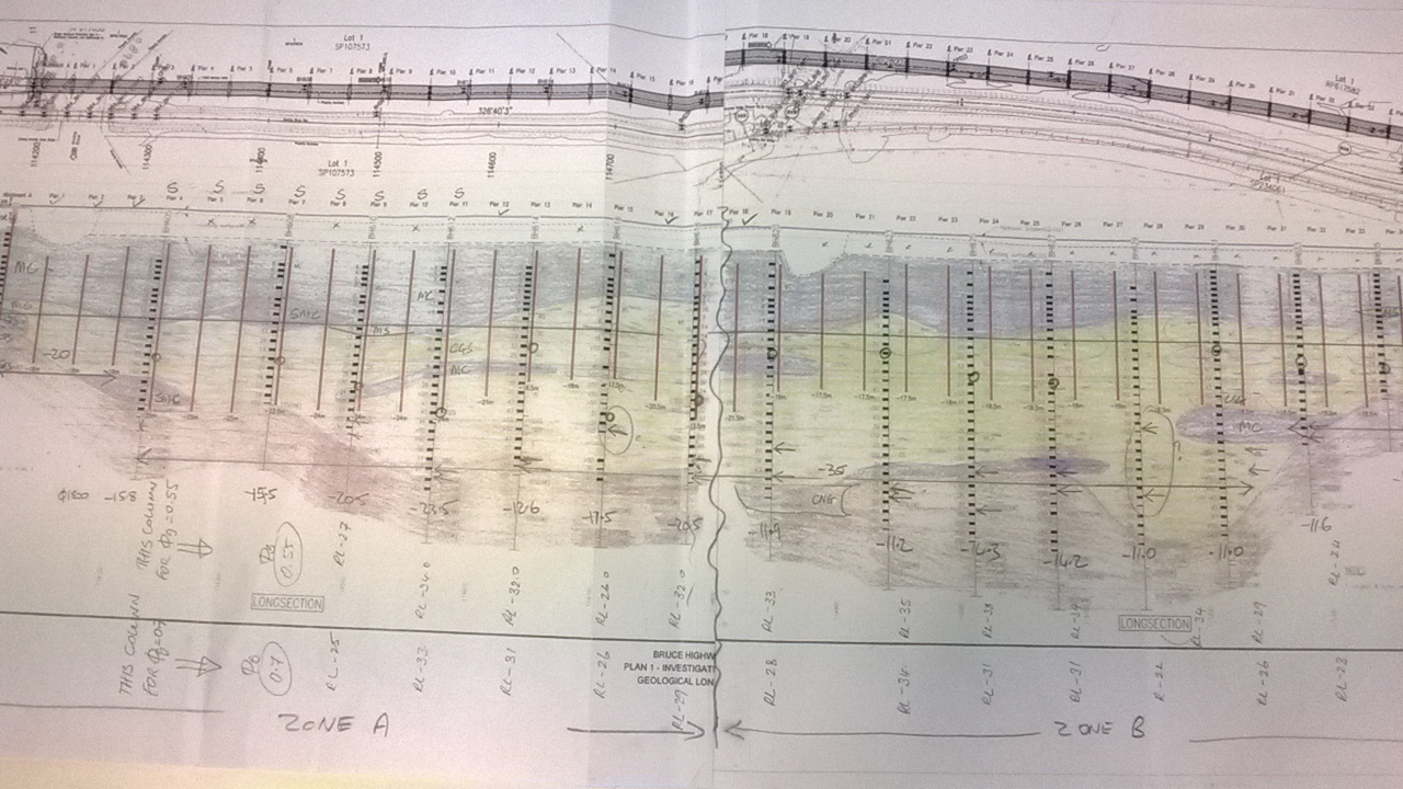
Fig 1 – “an artists impression” cross section of the ground
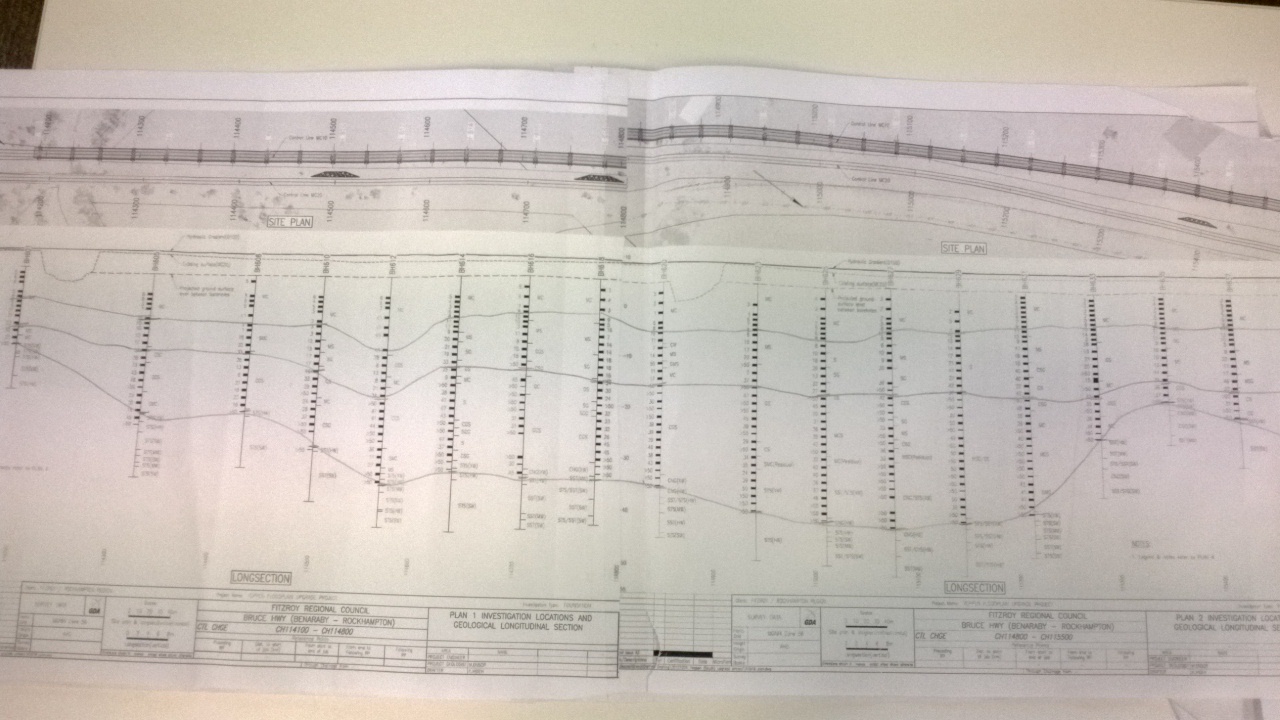
Fig 2 – showing the layers of the 4 main groups
The piles are subject to the following Ultimate actions: an axial load of 2550KN with Fx = 80KN , Fy = 50KN, Mx = 225 KN and My = 310 KN, Tension is expected to be 160 to 270KN. There are 43 piers on bridge 1 and each span is 35m. The actions vary slightly but not massively from pier to pier.
I’m not sure what the results would be if you fired it into the Bently software (my laptop hasn’t arrived yet) but I will see what it gives. I may even go for some rough hand calcs to see what length I come up with and compare to what the real engineers have designed. The design piles are driven 550mm diameter octagonal precast prestressed concrete. And vary in length. The longest single piles are 28m and the spliced ones go to 33m. The pile cap layout is shown below (fig 3).
Fig 3 – General pile cap layout
There is also a potential problem with the high temperatures causing a lot of cracking in the concrete. This has led to the client (Qld Main Roads) imposing some very strict monitoring on all the concreting works on site. Thermocouples will need to be placed at different points in the pile caps, columns and headers. More specifically this means that I’ll need to get about 2000 thermocouples and a bunch of dataloggers. A number of mix designs have been decided on to take forward to testing and hopefully next week we will pour a test cube (that’s a 1m3 not the small UK test cubes) and see how they preform I curing. (that could be blog number 2…)
I thought I’d add in a little weather update for Hoops – its been over 28 degrees since I got here and the forecast says it’ll hit mid 30’s this weekend…..how are things on the East coast of the US?
Found it: My arrival at the Power Station
Well I have found the draft of my first blog attempt so here is take 2!
Firstly this project is HUGE!!! Carillion are the lead contractors for Phase 1 of the £8 billion project to regenerate the power station and surrounding area. They will be building 2 apartment blocks between 8 and 18 floors in the sliver of land between the power station and the railway line. A good picture of it and explanation are here: http://www.costar.co.uk/en/assets/news/2012/December/Battersea-first-phase-powers-up/
They are going down 2 floors behind a cofferdam made from sheet piling hopefully without disturbing our neighbours-Network Rail and Mace in the power station. It is basically Ex COFFERDAM on a massive scale! (John you would be in heaven here!) They have finished the cofferdam which is made of sheet piling to provide a cut off 1m into the London Clay which is around 8m below ground level and they are now welding the seams. The main activity at the moment is piling the 1700 piles that will make up the raft of foundations! They have around 3 piling rigs and a lot of excavators dancing around each other on the pretty confined site.
Here are some pictures of what is going on:
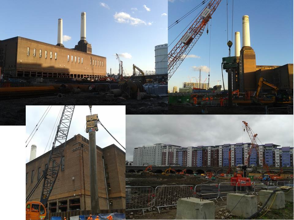
There are 3 main sub-contractors working on site: Appleton doing the sheet piling, Skansa Cementation doing the piling and O’Keefe seem to be doing everything else including excavations and drainage. It is quite an unusual set up as there is another company Elliot Thomas who run the site allocation as it is such a large development and Mace are already working on Phase 2 which is the redevelopment of the power station itself. We also have London Underground conducting borehole testing for the new station that will be built in the later phases. As the lead contractors Carillion seem to be more of the project managers of the site at the moment.
So far it looks like I am going to take on the role of one of the Section Engineers and I get to look after Utilities going out/into the site (aka OIC power and shitters!). We are looking to pipe jack a 375mm dia foul water pipe under Battersea Park Road into Thames Water’s existing sewer (and I need to get it adopted-glad I listened in the drainage lecture!). I also need to get our high voltage cable hooked up to the mains by the 1st April otherwise we have to pay for the generators for longer.
So far they have had big issues with the weather on site as it is turning into a nice muddy puddle-including the piling mats. They have had issues with the 6F2 material they have been using and the fines have been becoming a muddy slurry rather than a solid platform. There is potentially some scope for a TMR along those lines. I also attended a 4C’s meeting (something about Collaboration, Co-operation and some other C’s no-one seems to remember) which is basically a daily O Gp between the main contractor’s Foremen and Carillion. I could not believe the amount of whinging they made about not having a smoking shelter down in the main working area and then the logistics and temporary works design (TWD) that went behind putting one up! They even need to get a TWD to put up a barrier! It is really Health and Safety to the max and I now really respect the fact that we can trust our soldiers not to throw themselves off the top of the excavation they have just dug. I think they need a Sgt Major on site just to do the H+S patrol!
Anyway that is enough for my week 1 excitement I will attempt to put a few photos up and I will continue to chat up the guy from Mace to get a tour of the power station and trip up the chimney!
Where did my blog go?
Well I have just wasted about an hour and a half writing my first blog all for it to disappear into the ether despite saving the draft! So if anyone knows where it has gone please tell me where to find it! It isn’t saved in my blogs and I can’t find it in the HTS part-it seemed to disappear when I previewed it.
Anyway here is the truncated version:
I am working on this part of the project which is HUGE!! http://www.costar.co.uk/en/assets/news/2012/December/Battersea-first-phase-powers-up/
It is basically Ex COFFERDAM building 8-18 floors with a cofferdam right next door to the power station and the railway lines running into Victoria. It looks like I will be OIC HV cables and the foul water main (yeah sewers!). I did write a whole page about who was doing what and how surprised I am about the amount of hoops that need to be jumped through to get stuff done but that has disappeared! So I will keep this short and hopefully find my old post or learn how to use this stupid site before next week!
Roles and Responsibility?
Below are a few observations of my time in the design office so far, a continued criticism from the Orator is that there’s not enough reflection in my work so I’m trying to plug that gap slightly, this started off slightly more formal then it ended up however with a little pruning it will end up in AER 5. The final point is an observation on where geotechnics fit in to the grand picture, mainly at the bottom (pun intended). Sorry no pictures today, my desk is mainly looking dull.
I have been designated a Graduate Geotechnical Engineer, the positions more senior to me are:
Design Engineer – a number of years design experience, 3 in section.
Senior Engineer – A chartered engineer or geologist with commensurate experience, 2 in section.
Principal Engineer – An experienced Senior Engineer coordinating larger projects incorporating a number of junior engineers. 2 in section.
Associate, Project Director, Technical Director – Individuals with significant experience and typically dealing with checking, budgeting and oversight rather than design.
My presence at Ramboll is for a very specific purpose, to learn the more technical aspects of the civil engineering profession. My willingness to assume responsibility and ability to organise have been proven elsewhere in my career; by contrast for a junior engineer searching for competencies outside of their immediate day job opportunities would be very limited. Comparing this environment to that of a site based graduate working for a contractor the points I would note are:
- Responsibility. Both roles lack responsibility however the day to day tasks of a contractor are mundane and frequently just involve box ticking type inspections, there is very little thought beyond the consideration of safety infractions of particular operations. A contractor learns more through conversation with and observation of their line managers, from my time with Osborne there was not much of a mentoring type relationship. A designer by contrast is responsible for their design and must recognise the limits of their own competence, a designer learns by doing whilst mentored by a more senior engineer.
- Understanding of CDM. CDM is a fundamental aspect of construction in the UK, it shapes every stage of design and delivery. Much of the work seems to be completed early in a design, certainly from my experience as a contractor CDM was something that was done to you and to hear it’s title in conversation was a rarity. A contractor does get to understand buildability fairly quickly a benefit of being exposed to tradesmen from an early career stage. If you accept that much of CDM is completed in the early stages then it must be the designer that is doing it. This means a relatively junior engineer who has probably not been exposed to site work and is basing their work on university designs where things are wished in place. I would pride myself on being able to think through a problem and how it fits together in time and space and have found myself picking up aspects of design too late. An example has been designing the retained height of a wall to finished road level forgetting that a road needs to be dug out before it can be constructed therefore increasing the retained height of the wall in the temporary condition. How are junior designers expected to pick things like this up? The lesson I learn is that even though CDM felt like it was all complete by the time it hit site the truth is: Buildability needs looking at long before the on site operation begins. Unfortunately the reality is this is next to impossible due to time constraints on site.
- Application of knowledge. On site application of knowledge is rare and extends more to techniques rather than principles, the techniques are normally learnt from a more experienced manager or perhaps even a tradesman on site. The graduate contractor is quite possibly surrounded by managers of various backgrounds and depending on the company is probably in the minority as a civil engineering graduate. As a result they see many of their colleagues and line managers avoiding true engineering. It is quite natural for a graduate contractor to become relatively blind to technical issues or even shy away from them altogether. I certainly felt a couple of times like I had a bit too much of the classroom about me however soon realised this was wrong as others were blindly skipping along telling people to put their glasses on whilst ignoring bigger issues. Possibly this is natural due to the delineation of design responsibility and risk, why try and solve someone else’s problem? Actually it’s not a in contracting company’s interest to get involved as is muddies the waters when it comes to claim time.
- Management of people. A design engineer gets no exposure to managing people, reading the ‘Successful Chartered Professional Reviews’ book combined with the ICE DOs management and coordination is a key attribute of a Chartered Engineer. Whilst I acknowledge that the reviewers are asking the question ‘would this person make the right decisions if they were placed in the appropriate appointment?’ rather than ‘has this person made the decisions expected of a CEng?’ it must be hard for a designer to demonstrate that the answer to the former question is yes. This lack of management could possibly extend for the first 10 – 20 years of their career depending on how quickly they rise however ultimately some of these people must eventually become team directors and perhaps even board members. Times on site as residential engineers or secondments to contracting companies can close some of the gaps but possibly not fully. This is perhaps where matrix structures fall down and a more project based organisation has the potential to develop better future managers and leaders as there would be a greater exposure to project managers (who should be good people managers) doing their jobs. The opposite is of course true for a contractor, they are exposed to a huge variety of people from an early stage. Early on at the lower end of the spectrum they have to manage, cajole, bribe and blackmail them into doing what is required on site. As they become more senior they then have to ‘manage’ their own line managers by managing expectations and diplomatically telling them that some ideas are stupid.
-
Uniqueness of geotechnics. I am coming to the conclusion that Geotechnics isn’t where the cool kids hang out. We all know that work in the ground carries a huge amount of risk and that geotechnical engineers are often the key to reducing that risk to acceptable levels. However the geotechnical section always seems subordinate to everyone, for example the Associate in my section regularly seems to be picked on by an Associate from highways; the Senior engineer who is borderline special gets picked on by his equal from Building Structures. I don’t quite get it, I know our part of whatever is built is buried or hidden away and our work effectively becomes the enabling work but it’s always pretty important, and always on the critical path, it’s like we’re the RLC of the design world. For example highways need a large number of gantries designed for roads, the loads never changed, the kit that gets hung on them rarely changes the only different bit is the ground underneath and yet we are definitely working to them rather than the other way around.
Any takers? Assistance much appreciated. There is no prize!!!!
Situation
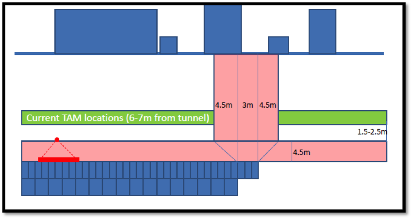
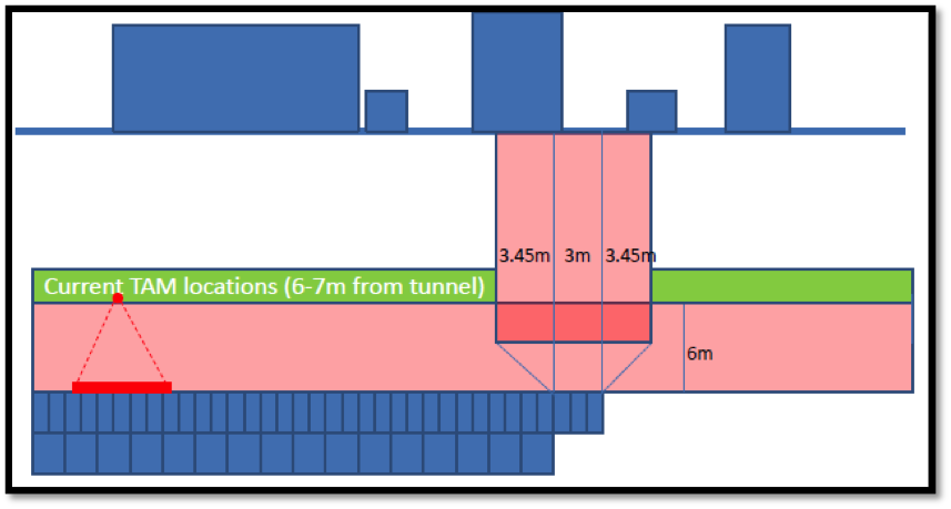
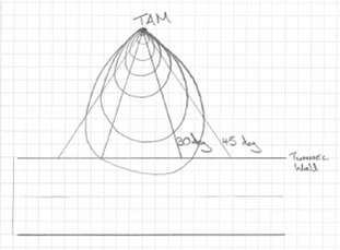
Have a look at the sketch below. As the tunnel is being excavated, above the tunnel there is a ‘umbrella’ of grouting (this is constructed using TAM’s, Tube A Manchette). The grouting is there to mitigate the settlement on the surface. However there are no grouting zone, that ensures the pressure from the grouting does not effect the exposed face (in this case 3 rings, 3m). The horizontal no grouting zone runs parallel to the tunnel at a depth of 4.5m, the vertical zone moves with the construction, however it’s dimensions are dictated by the exposed face (3m) and the angle that the TAM pressure influences (currently at 45 deg)
Issue
The problem is that the amber trigger levels have been hit, ref the surface settlement. The subcontractor want us to reduce the vertical ‘no grouting’ zone. This can only be achieved by reducing the angle from 45 deg to say 30 deg as the exposed face can not be reduced.
Calcs
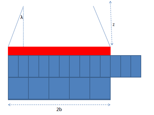
If the pressure on the face is approximated as conical spread from point of injection. My preliminary calcs suggest that a reduction from 45 deg to 30 deg will impose a 300% increase in the pressure, as the area will reduce from 61m2 to 20m2.
However this is a very rough approximation, as many of the stress counters from the TAM will be contained within the 30 deg. What Im trying to calculate is the % of stress that will be contained within the 30 deg compared to the 45 deg. Does this make sense? How the hell can I do it?
Use of MathCAD
Morning all,
I have just sat through a seminar on MathCAD. Admittedly by a specific MathCAD training company.
The software appears to be able to do all that excell can but with a simpler interface and transparency that allows easy checking.
I struck me that a knowledge of and access the program may have saved many hours of student time during design exercises, and probably lecturer time in marking. I understand that Excel has it place as a readily available and flexible tool that is relatively inexpensive, but wonder if for STRE design work MathCAD may have a place (or whether it is used already?).
I am interested to know what your experience of the program in industry is:
- Have you heard of it?
- Do you use it and to what extent?
- What do you think of it as a design tool?
- Do you think it would be suitable for use on PET course/STRE’s?
Thanks all.
Proposals, Presentations and Thongs
Over the past week I have been working mainly on the proposal for Ballinyoo Bridge referred to in my last post. The issue with the site is that it is just so far away from anything and all quotes for geo, survey, road safety audits, and visits all include the cost of substantial amount of travel and accommodation. I evaluated the 3 Geo quotes and found them all to be fairly similar in content, which made my job easier, but 1 was significantly higher in price. I assumed that they just didn’t want to go up North but was surprised when they called to express their interest and ask if there was anything else that they could do to assist their quote. It was really a 2 horse race between the others who were coming in over $30,000 cheaper for the same service. I had to get the quotes amended to allow for pavement design and a different drilling methodology. This drilling issue that arose whilst talking to the clients Works manager, who stated that the river was in flood due to unexpected rains in North WA and would probably be so for the following 5 months. This meant that the geotechs would not be able to drill a BH at every future pier (as dictated by the Aussie code), and would therefore have to drill from the deck of the existing bridge. It turns out that this would only be a couple of $k so not a huge issue. The bigger issue is that the drilling would effectively close the single lane bridge and hence the road for about 10 days. The shortest detour would be about 600km, so it looks like the geotech investigation will have to wait until the low level (ford/culvert) crossing was trafficable. This will be about 3 months if the rain holds, so even if we progress with design without firm Geo, the construction is not likely to be completed in their dry season unless BG&E pull out all the stops and complete it in a couple of weeks. I was able to reduce all the quotes by a couple of $k by organising with the Shire works manager to provide a water source to cut off the water-boring costs.
My initial experience of the BG&E flat organisation structure was good. The idea being that it allowed everybody to interact with each other and had direct access to senior engineers and directors for building effective project teams. Though this obviously shook my being to the core as I found it impossible to understand how anybody could work without a organisation wire-diagram, it appears on the surface to work. Recently though, the cracks are showing somewhat. Directors employing junior engineers direct and not involving their ‘line managers’ means that the junior engineers are not being managed effectively and often have too much work to deliver at the same time. This could be eliminated by involving line managers to manage workloads, but this is an additional cost to a project. This situation came to head when an error on a project meant that a junior engineer was accused by a director of negligence and the line manager had no ability to protect him because he knew nothing of the situation. I think this may be something Rich Phillips is looking at but it made me appreciate the military management structure somewhat, and thought it would be a good thing for industry to take on.
I have been to 2 presentation over the past 2 weeks. The initial conference was about the new products that Hilti were bringing out. A recap on the use of chemical anchors in design brought back memories of the hospital project where Chemical anchors were seldom designed, but were the “get out of jail free” card that contractors were constantly abusing to save time. The second part was an introduction to a hollow drill bit that is used as part of the system to suck dust out of a hammer-drilled hole in order that it is immediately ready for chemical anchoring. The presentation concerned me so much that the practice at the hospital was so poor, I immediately emailed the engineers to make sure they were in the loop, and even emailed to presentation to the main culprit subcontractor with a summary of why the particular drill bits would save him money.
The second presentation was organised by Engineers Australia (ICE equivalent) and was by a civvy who worked with the Defence Science and Technology Organisation (DSTO), so I decided to go to support the military. Turns out that all that is Science and Technology in defence is not that interesting. 1.5hours on radar waves pretty much killed me, though I did rouse briefly when he spoke about the large civil structures designed for the systems. There was pizza though. For my CPD log I will state in the “What did you learn from this activity” box, “Always read the presentation summary before you attend.”
In other news, Nicky and I went down to Cottesloe beach and joined the world record attempt for the ‘largest number of people connected on the sea on inflatable thongs.’ Before you get too excited, a thong is actually a flip-flop over here; but when paddling out to the line-up, there were plenty of thongs on thongs so I am not complaining.
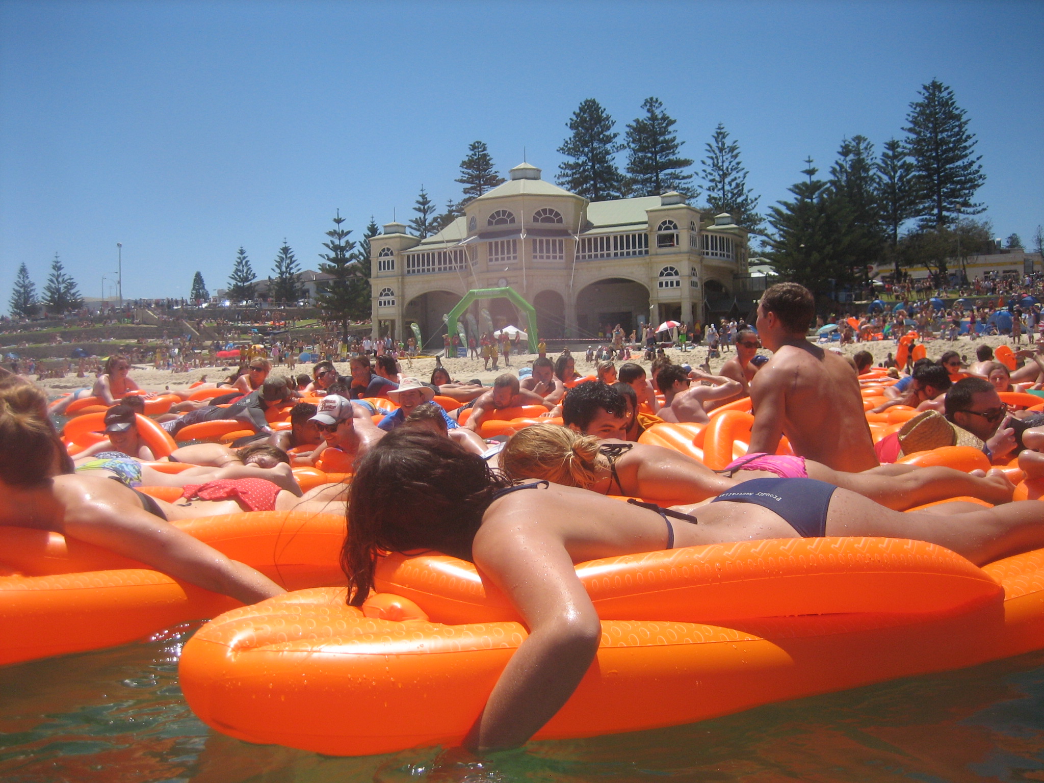
She is going to have some terrible tan-lines!
You don’t see that every day!
This is insane, its got Wilie E. Coyote all over it!