Conveyor 620 continues.
Blog No.3
My work continues along conveyor 620 and I am now following a fairly set process to complete the different foundations.
My last blog concluded with the piling almost complete (6x steel still to be driven) and preparation for the next stage of the foundation construction. So if I explain what I have done for Transfer Tower (TT)615 the process for all the other bases is more or less the same.
So initially I set the pile cut off point at 50mm (cover) below the finished top of concrete (TOC) level and cut the piles.
By extrapolating the information from the foundation GA drawing I set the level of the shallowest element (the 300mm main slab) included 50mm for the blinding, and excavated the entire base to that depth. This included 800mm of additional horizontal space around the outer edges for the shuttering to be subsequently placed. Once this initial excavation depth had been dug I then set out the slab ground beam locations and services that required further excavation (usually 500mm – 1000mm depth from TOC) , again including 50mm for the blinding. Once excavated the bases look something like this.
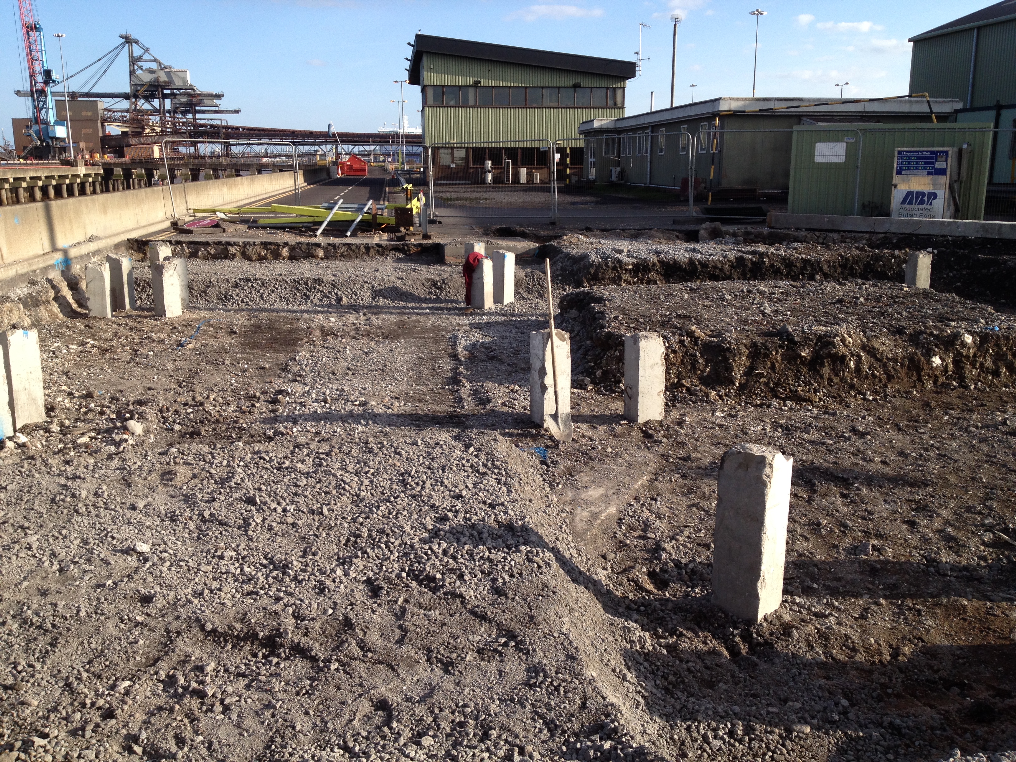
TT535 piles cut 50mm below TOC, excavation complete for slabs and beams.
I then cubed up the foundation, ordered and placed the 50mm blinding layer. Semi dry concrete was used to grade the slopes from the ground beams to the slab locations.
Once the blinding cured I set the level for the piles to be crunched and the steel exposed (usually 75mm above the blinding as the bottom cover is 75mm) and the rebar was then broken out. Once the steel was exposed the electrical subcontractor came in and placed all the earthing cables, welded to the pile rebar.
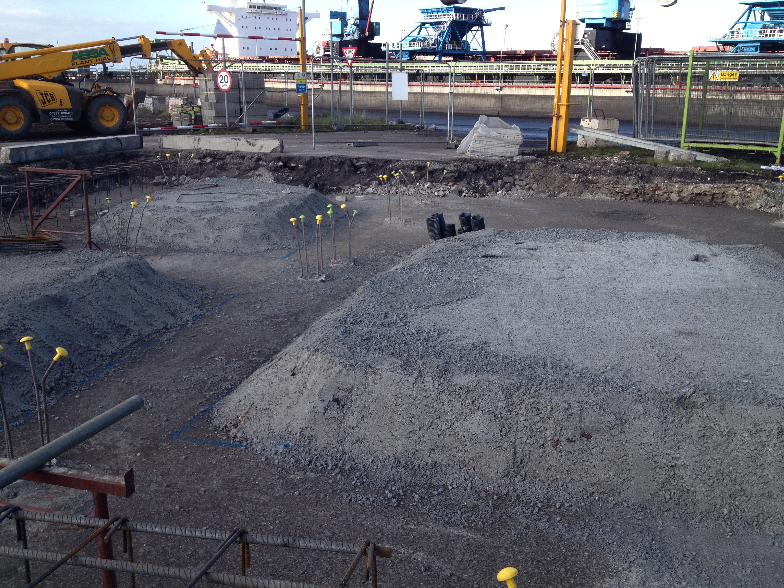
TT615 service pipes placed, blinding poured, slopes graded, piles crunched to expose rebar.
Using a total station I set out the extremities of the foundation, placed the nails, strung out the edges and sprayed the lines for the steel fixers.
The fixers then arrived and started positioning the steel reinforcing and I was checking the configuration, cover and heights.
The joiners placed the shuttering around the steel and again I checked the alignment and cover. Once the main body of the steel was completed I set out the positions for the starter bars for the various upstands and walls that come out of the foundation. These starter bars still need to be placed and the next stage will be to place the bolts for the structural steel, prior to pouring.
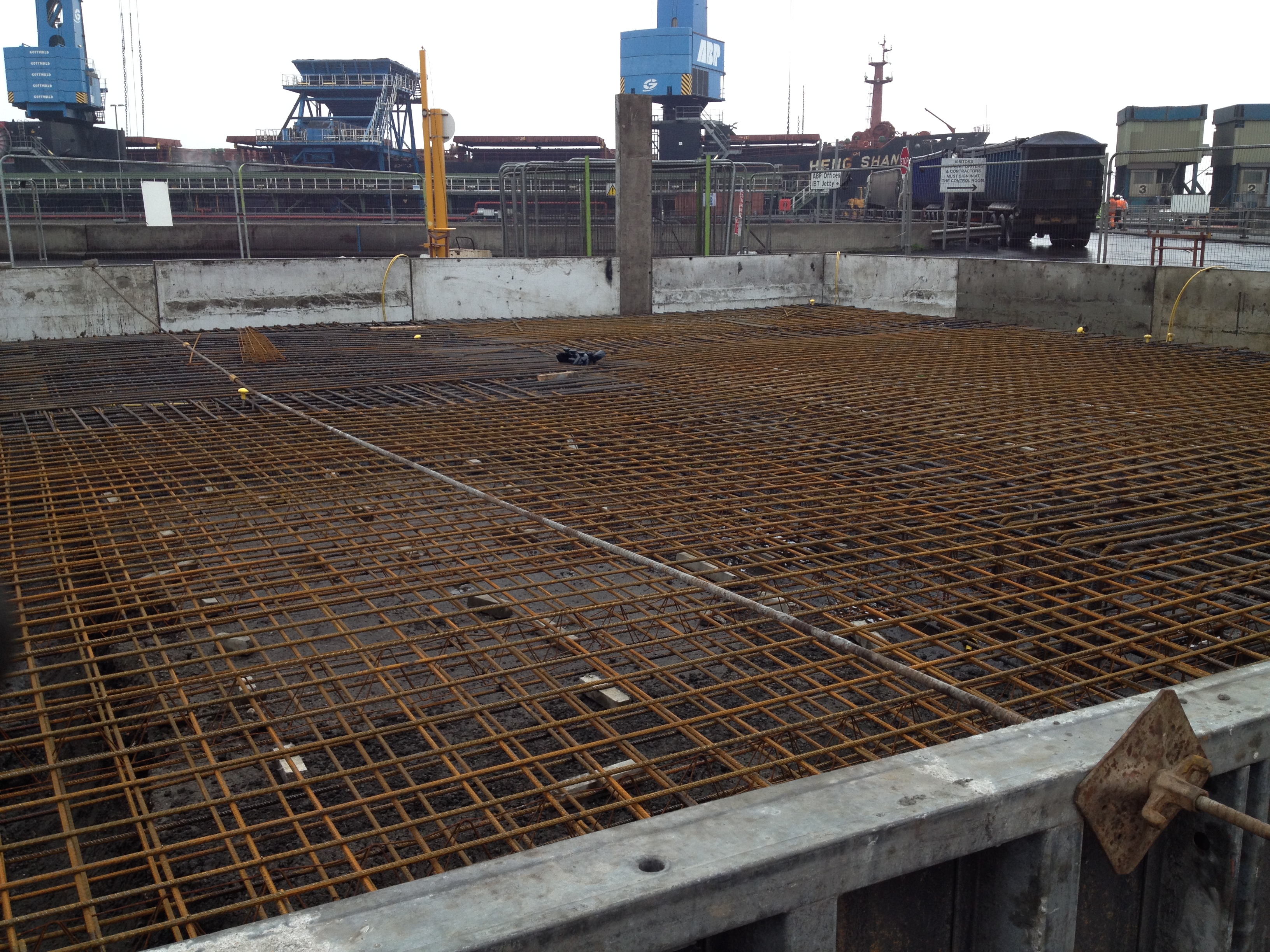
TT615 steel and shuttering in place. Starter bar locations for upstands and walls marked out.
This was the process I conducted for TT615. TT535 is awaiting the steel fixers and I am overseeing the excavation of Trestle 2-4 and the GTU as I write. It’s now a case of keeping the process up and ensuring I am 1-2 days ahead of the various teams of labourers, fixers and joiners spread across my section of work.
Reflections.
Services. The drawings do not include all of the services that may need to go into the foundation. I have only been caught short once where 6 service ducts needed to be placed into one of the bases and were not included in the GA. Luckily this did not require much remedial action and I discovered the omission before the blinding was poured (just). I did lose one of the smaller pads I had left for the construction of the slabs as the services went through it, but the fixers managed to make some steel chairs to support the slab steel as it was only a small area. Cleary this has a small cost implication as the ‘void’ will now have to be filled with structural concrete but as we are talking probably 1m3 I’m sure it will not be a problem when we come to pour.
Even when I found the drawing for the service ducts and was about to start the excavation I double checked with the electrical sub-contractor that it was in the right place. He agreed it was coming through the slab in the right place but the proposed alignment was incorrect. He then produced version A of the GA drawing (I was on G) and asked me to realign the proposed route as the electrical services had been designed to his drawing. On this occasion it did not significantly alter things but apparently this has happened on several occasions, with different drawing versions creating confusion and additional work. I now ensure that I communicate with all the service stakeholders prior to any excavation.
Speed and Accuracy. It surprised me just how quickly on completion of the blinding the steel fixers were all over the first base I had prepared. Having managed to place the blinding a day ahead of schedule I thought I had bought myself a little breathing time but I think everyone else thought the same. I set the nails and sprayed the extremities of the foundation and the fixers were on the slab before the paint was dry! I had a concern about 2 of the points appearing to be not quite square (on confirmation of the positions with a tape) and so queried the off sets on the GA. By the time the error was confirmed and I had the opportunity to re-shoot the positions the steel had been placed and the shuttering was being positioned. I spoke to the foreman in charge of the joiners and pointed out the adjustment required but as a couple of the holes for the shuttering had already been drilled in the blinding they simply ignored the new position and cracked on anyway.
Shuttering and steel out of position.
This left an approx 30mm extension in the base. I was not overly concerned as the cover was still sufficient, the alignment still straight and the edge did not tie into another structure. I highlighted the issue to the section manager who agreed with me and did not see it as an issue. What did surprise me was the lack of care shown by the joiners. The issue was highlighted in good time for them to only have to conduct 5-10mins remedial work. By the time the section manager had seen it, if he had decided that it needed changing the amount of remedial work required had significantly increased as all the shuttering was in place. Perhaps the joiners experience led them to know what would need changing and what wouldn’t but I’m not sure they have ever heard of the phrase ‘a stitch in time saves nine’. The experience has led me to be extra cautious when studying the GA’s. In this case it was difficult to see the error prior to them being set out and due to the speed of the follow up activities after marking out the foundation it proved difficult to actually prevent the subsequent errors. It subsequently took me half a day to set out the dozen or so nails for TT535 as I wanted to be 100% confident in the positioning after this experience.
Responsibility. The original section manager I was working to has moved to another site. This has prompted a reshuffle in the section, where the previous section engineer has moved up to section manager and one of the site engineers has moved up to section engineer. That has left 2 site engineers responsible for all the work across the site (bar the silos). Last week the other site engineer was covering a night shift as the steel subcontractor is significantly behind schedule and having to make up the time. This quickly left me as the only engineer in the section and although the section engineer was mucking in I found a lot of extra work on my plate and have now been overseeing the construction of another substation that I may blog about in the future.

Thanks Joe.
When you say semi dry concrete was used for blinding,how was it specified – recipe or prescription? SC2 I suspect? Noting your challenge with drawing revisions – were drawing rgisters and issue sheets covered on PET phase 1? Is there anything that needs to be added/changed? I ask becasue the AutoCad/drawing office protocols part of the course is under review at this very moment. Noting the speed with which the fixers set to work, I wonder if there would have been a claim in the event of you changing your marked positions. Is there a process for signing off the setting out? How would a change work contractually and commercially? Were they working at risk because they are ahead of schedule on unconfiormed setting out or are you exposed to risk because they have moved onto a prepared section and have a right to assume markings are correct?
Richard-Carillion use Aconex to manage their Drawings, RFIs and RFCs. Is it worth introducing an explanation of that onto the course? Is it something that is used widely or just on big projects?
Joe-How are you getting on with the surveying??
Hi Ange,
That is the question. I have not seen Aconex but have worked with Buzzsaw, and 4Projects in the past and seen Conject. I suspect all are similar. I do not know what 170 use (if they do at all) but they will need to if they are going to go into BIM so there is an suspscion that this should be touched on in PET Phase 1 unless it is so intuitive and prolific that you all learn enought by osmosis on phase 2/3. Did you learn about and find Aconex obvious enough that it doesn’t need introduction on Phase 1 or would a piece on drawing management and control have been useful? What would you see as the Key Learning Points?
P.S. Did you see episode 1 of Mind the Gap presented by Evan Davis? If not find it on the iPlayer because it’s got clips that anyone in London wants to use in a presentation in Phase4 including Mr Big of Battersea and your flats…
Get well soon. Or is it gris on and man up wet pants? I struggle with the modern vernacular…
Joe, did you use a mechanical pile cropper for breaking out the rebar on the pile tops or men with breakers? I need to make a call whether to go with a cropper or a reliable bunch of Irishmen with a set of breakers (DB Farrels). The cropper on its own works out cheaper, but with added plant costs and the additional time I think the Irish might be the better option. Did you still have to spend time breaking out the reinforcement after the cropper had finished? And was it a problem fixing the reinforcement into the bars protruding from the piles?
Rich,
The semi dry is prescription and I simply asked the Lafarge supplier to bring it like that. In essence its the same mix as the blinding with a lower W/C ratio. Once its been used in the drier state its wetted up for use as blinding elsewhere.
Drawing registers and issue sheets were covered briefly and in probably enough detail. Graham use 4Projects and it is a very intuitive system that I check daily. All of the drawing updates come through a central point and are sent out as a daily email and it is also easy on 4P to find the most recent drawing. In this case the majority of the drawing revisions had been pile co-ord changes (due to my breakages) and a slight shape amendment. The electrical design was done to the original drawing and therefore, technically, version A for his purposes was still valid and he was probably just being lazy in not reprinting and laminating the subsequent additions! I actually find the monitoring of the drawing additions fairly easy using 4P and I just ensure before I set out anything I am on the current edition. I’m not sure a bespoke lesson on this is required as it is definitely something I just took on when I arrived here.
The setting out did not effect the steel fixers as the RC details did not change. The fixers arrived, placed the steel as per the drawing and moved on. As far as I am aware there is no signing off process, everything is too fluid for that, however I get someone else with a fresh set of eyes to look over the positions.
There is an element of risk with it being ahead of schedule but to be honest its not really a problem. There are several steel fixing teams on site and to start they used my section as a ‘fall back’ when they were delayed elsewhere. So although they were on my foundation immediately they then stopped for a day or so before the full team arrived and then they cracked it out very quickly. They build the steel to the RC design largely regardless of the setting out, which they only need for the positioning to get the cover right. If the setting out had been dramatically wrong they would have flagged it up and it would have become a priority to reshoot. If not the last resort would be to get in the crane and move the steel as required.
On reflection of the CAD stuff we covered I think it would be much more useful to include with slightly more in depth surveying lessons. We spent a good few periods drawing out 3D shapes and whilst probably useful for Phase 3 I think the time could be spent more wisely as it happens right at the end of phase 1 just prior to this phase. I have used a total station a lot and it only took the site engineer a couple of hours to show me the ropes but what would be useful is learning how this equipment interfaces with CAD. For example, as-built surveys are conducted quite a bit with the information put into CAD to check alignments, distances, heights, angles etc. Combining the surveying with CAD for this purpose would be useful. Learning how to extract the info from the TS, plot it into CAD on the correct co-ord system and then manipulating the data to confirm the details against the GA’s would have been more useful for me.
Ange,
The surveying has been pretty easy to be honest. It took the site engineer a quick lesson to reintroduce me to the laser and dumpy levels and I picked up the total station and GPS equipment in a couple of hours, having never touched them at uni. The setting out just takes time due to the accuracy required!
Pete,
The cropping of the piles was relatively simple but there are a few things I would recommend.
Ensure that the first pile cut is right ie 50mm below TOC (for us) as there have been instances on site where the piles have been cut too low, down to 50mm above blinding (ie second cut). This means that the piles need drilling to insert additional steel. The first cut takes off the top of the pile including the steel, the second breaks out the steel to be tied into the foundation. Simple I know but I have seen piles too low on this site creating a headache for the engineer involved (not me), both after a b******ing and a redesign.
The first cut using the stihl saw takes off the upper most section including the steel to 50mm below TOC. The lads just cut the four pieces of rebar in the corners and used the excavator bucket to knock off this top section.
The second cut was again initiated with the stihl saw, avoiding the rebar, at 75mm above the blinding (bottom cover). Then the pile cruncher, suspended from the excavator arm, dropped onto the pile top and after a couple of crunches it had removed the concrete. They can crunch the concrete and keep it in the cruncher and swing it straight into a dumper, reducing the time clearing it up. There is work required after the crunching due to the limit of the cruncher and the surface it leaves.
Once they had crunched as low as possible (100-150mm from blinding) the stihl was used to cut a lattice into the top of the pile (plan view) down to 75mm above the blinding, creating blocks of concrete. These blocks were then cut out using an electric chisel. This creates a decent, clean, level pile top at 75mm above the blinding and the steel then exposed to 50mm below TOC, for a 700mm ground beam – 575mm of exposed steel.
I have seen the blokes manually cut and break out the steel using a sledge and I would recommend a cruncher every time. Graham also had the same discussion about the validity of getting a cruncher in but if you have a significant amount of piling to do its def worth it. I’m surprised that you think there will be a time saving using blokes to break out the steel, you must have loads on manpower? We were breaking out the 575-700mm worth of steel and it was done under a minute for the crunching alone (2 x crunches). I had 2 guys cutting with the stihl, crunching, latticing, breaking out with the chisel and sweeping up on one pad and they had 28 piles done in around 2 hours. Manually breaking the concrete and cleaning it up would have taken longer.
As long as your pile alignment is good the fixers will have no problem tying them into the reinforcement. On my structures all the piles sat under the ground beams and so I could visually check the alignment of the piles as they were going in for additional confidence.
However, quite a bit of the pile steel I exposed needed earthing cables welding in place. They used 4 small bits of rebar to create a square, tying in the pile rebar and then welded on the earthing cables. You’ll need to make sure that anything like this is completed before the fixers start tying in the structural steel, as whilst it can be done subsequently, its much more awkward and time consuming.
I hope this is of use and makes sense? Happy to send any piccys if required.
I wouldn’t be surprised if your Irish blokes know the guys on this site. One of the guys here is off out to Oz next week, he’s already been Brisbane way for four years previously and has decided the pay, weather and women are worth a return trip.
Joe
Sorry but I have not been on the blog for some time.
This is excellent and good DO stuff. By all means blog but watch that you do not get too embroiled.
All the very best.
Neil