Archive
It has been several weeks since my first blog but in that time I have been on a steep learning curve and very busy.
Most of what I am about to mention I had actually written in a draft blog but I failed to finalise and publish it before the writing of AER 1. To be fair most of what I did draft went into AER 1 so if you’re likely to read AER 1, I wouldn’t bother continuing from this point!
After my first real on site experience with the rail load out silo steel roof I quickly graduated from working as a site engineers assistant to being given a section of work to really get my teeth into. As such I have spent the last 3 weeks piling and resolving the 535, 615, Trestle (T) 2,3,4,5,6,7,8,9,10 and C620 Gravity Take Up Conveyor 620 (GTU C620). It is proving to be a great opportunity as I various issues that has thrown up.
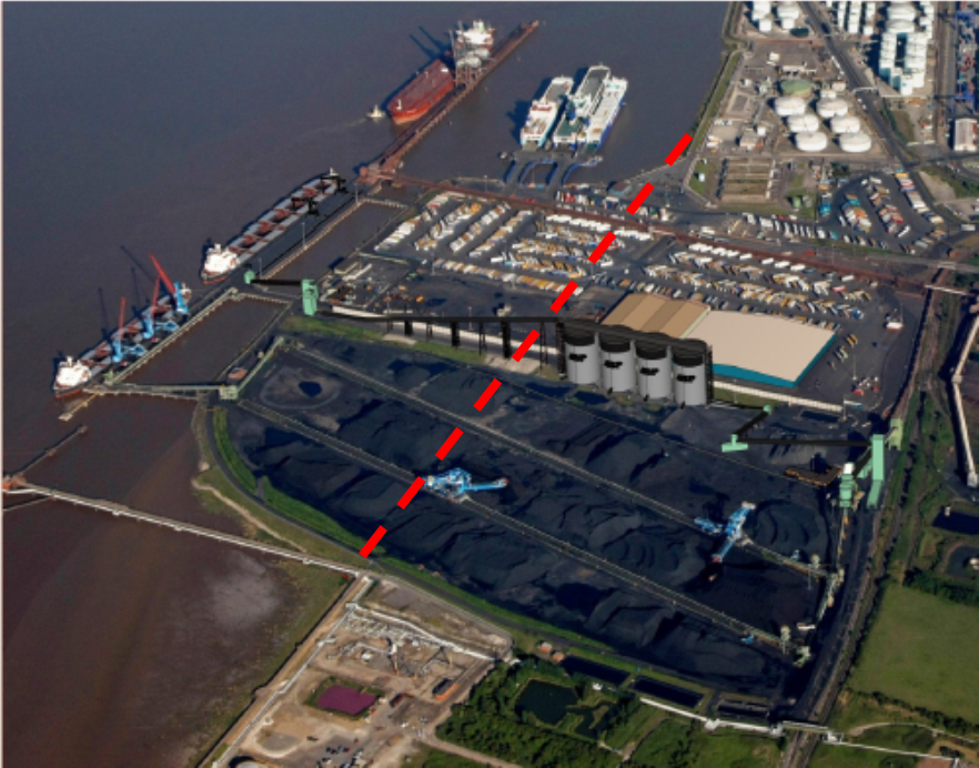
The following picture I prepared for AER 1 and highlights the area of the site I will be working on, effectively Transfer Tower (TT) am now able to work on this element of the project from the ground upwards and see the entire element through from clearance of the site to turning the conveyors on.
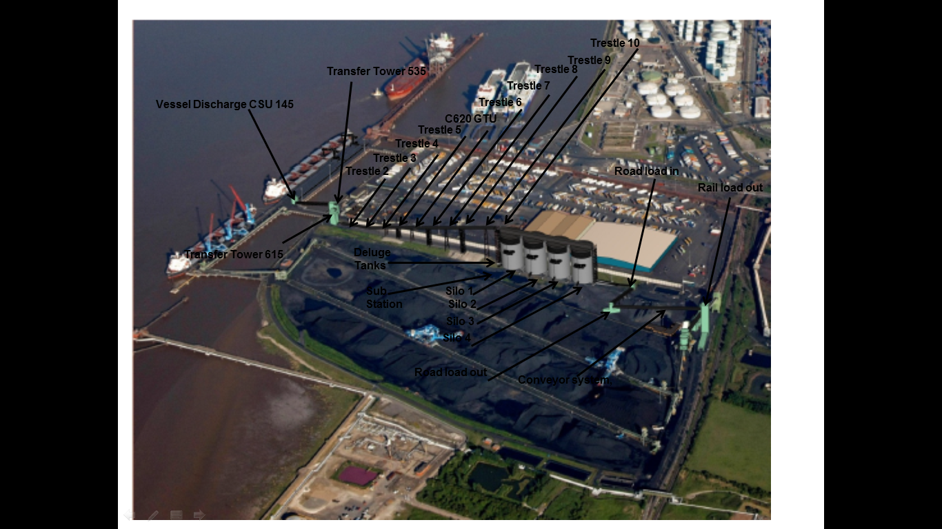
The first part of the work has been driving 163 x 27m (13m and 14m sections) 0.27m2 pre-cast RC displacement piles for the foundations of all the previously mentioned elements of the section. To start I was using the GPS equipment to mark out the extremities of the piling area for the plant to break out and prepare a suitable surface. This involves breaking through the 400mm concrete slab that was previously one of the main routes in and out of the complex for the HGVs (hence the thickness), clearing it away, backfilling with a suitable aggregate and compacting. Once the area had been prepared I marked out the exact locations of the piles for the rig to drive them through the next day. I was working 1-2 days ahead of the piling rig to ensure that it was continually piling, trying to minimise the amount of expensive standing time. All Royal Engineer Troop Commander bread and butter stuff up to that stage.
The main issue I had was pile refusal and breakages.
There were 25 breakages, 10 refusals and 2 where the final rake was too large and therefore required replacing. These issues were largely in a couple of the foundation bases.
From the surface it is difficult to establish whether the pile is broken or not and I naturally questioned what the driver was telling me when they started to break one after another. To that end I sat in the cab, with the driver, to see the breakages for myself. The driver was under the impression that the piles were breaking at around 5-8m. Once in the cab it was clear to see that obstructions were being encountered at about 5m due to the number of blows per 0.25m driven length significantly increasing (30-50 where normally 5-20, 5T hammer, 250mm drop) and this would continue through till approx. 8m. This band was where the breaks were suspected to be occurring as the piles were ‘kicking away’ from the driven course. This could be proven when compared to the penetration record of successfully driven piles where an increased stiffness (significantly increased blow count 50 -100) was seen at around 20m+ demonstrating that the toe of the pile had reached the correct depth. If the pile had broken around 5-8m this increased stiffness was not encountered as the upper section would shear off from the lower and simply slide passed it, thus not achieving the correct depth. This was not always the case but as a general rule it indicated a broken pile.
The procedure for a broken pile was initially simple as I would contact the designer with either a recommended location (predicted from the broken pile and 2D off set estimation) or request new co-ordinates. Within a few hours I would receive a confirmed new location to re-plot and drive. At times this new location would drive successfully but not as a general rule. A few of the piles in a couple of the trestle bases required 3 or even 4 replacement positions and the pads were extended in 2 directions to accommodate the new positions. In fact the increased slab dimensions negated the requirement for 6 piles in one location, reducing it to 5, due to the increased capacity of the shallow foundation. On 2 of the pads I decided to stop driving the piles due to the fact that any viable solution was becoming more difficult with the area quickly becoming an underground forest of RC.
The nearest borehole sample I could find was from approx. 100m away and confirmed this obstacle belt of made ground to a depth of 7.4m which included chunks of RC, railway sleepers and large rubber fenders!
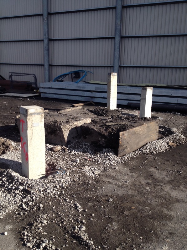
3 x rubber fenders dug out at 3M!
Various solutions were discussed from deep excavations to drilling and eventually the use of steel H-section piles. We managed to ‘find’ a 9.5m 206x206mm steel section to use as probe and drove it right through the middle of the most troublesome base. For my part this was a confidence boosting moment as a number of the management watched the pile being driven (having not been completely content with the number of piles breaking) and it demonstrated behaviour exactly as I had been describing. The number of blows increased at 4m as it entered the obstructions and the pile virtually stopped dead at 6m requiring an increased hammer drop of 850mm to persuade it through the obstruction. This it did and after 8m the number of blows reduced significantly as it had driven through the obstruction and continued normally.
I spent all day Monday consolidating all the paperwork and sending all the info (including the steel results) to the designers for a redesign of 2 of the foundations where a total of 6 piles still require to be driven. I await the outcome and if I have time I will have a bash myself to compare to the actual design that comes back – all good TMR 1 stuff. However things move apace and today we received the RC details for TT535 and 615, so the steel has been ordered and I have been back out marking pile cut off points for crunching and the base ground beam positions for excavation and blinding by the end of the week. As I type this the section manager has just handed me the remaining RC details for the trestle bases – no rest for the wicked.
A flavour of Mace projects in the city
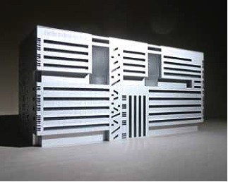
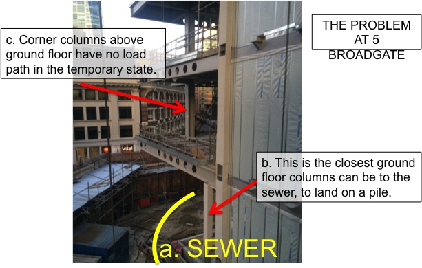
Last week I visited 5 Broadgate which is another Mace site. It is right by Liverpool Street Station and is prime banking territory. UBS is having built a 700,000 sq ft building, based on a single block form, with a gun- metal grey finish. At 12 floors it will include up to four trading floors, each able to accommodate approximately 750 traders, allowing UBS to consolidate its London trading operations into one building.
So here is the problem:
 I
I
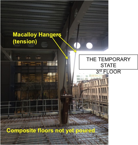
In order to overcome this issue the corner would be hung from a truss on the roof as well as Macalloy hangers on the 1st and 2nd floors.

Here is a picture of the 3rd floor with the Macalloys in use
The (big) truss on the roof cantilevers out to allow the perimeter column to hang in tension and suspend the corner. Jacking was used to ensure it had ‘picked up’ the perimeter.
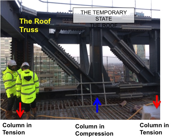
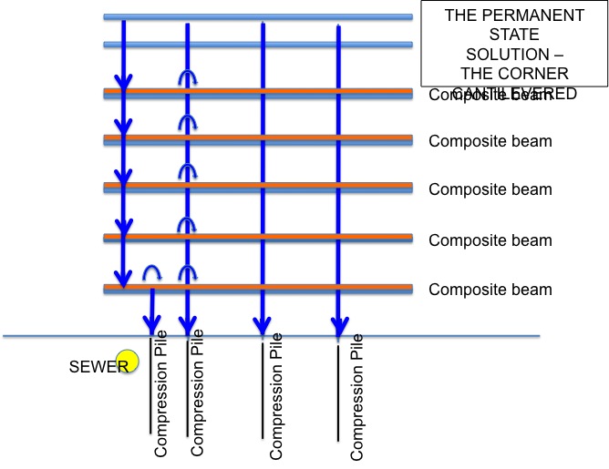
This system seems to have worked well on site. It is reasonably simple to set up and control (with jacking). Mace plan to pour all 11 floors of corner concrete at once so that there is no differential movement between the floors. The Macalloys and roof truss will be ‘stressed’ so that any elastic extension is accounted for with pre camber.
On the South Bank Tower we will also be using Macalloy cables, but ours will be used in the permanent design. The proposed force in them will be 7600kN. Anyone else got any experience with them?
A little Passive and no Active Pressure
The area on site known as the grout box is due to be handed over from ourselves Laing O’Rourke working on the C502 contract to another contractor working on the c510 contract. The C510 contract is responsible for tunnelling through to the Liverpool street station ticket halls. As part of their contract they are required to carry out ground stabilisation through the use of injection grouting. The area requiring grouting is accessed from the C502 site and as a result we have been busy excavating a shaft and preparing the area for them. The grout that is to be injected behind the pile shaft wall first has to be piped into the grout box and this required the removal of a pile. The removal of the pile threw up a number of questions around the stability of the pile and ground given that it would effectively be suspended and relying on skin friction to stop it moving downwards and closing the gap. In addition and probably more importantly the pile would have no active pressure that it could use to resist the passive pressure of the soil and water behind the pile. To overcome this a reinforced concrete beam was cast into the piles to act as a whaler beam and fix the now free end of the pile. The task of organising the team to cut the pile and remove the concrete was given to the new boy (only once tea making duties were completed). After a period of scratching my head, I decided that the best means to attack the pile would be to get my old friend the diamond core drill and to stich cut the top and bottom of the pile and then to use the 3T excavator to break up the concrete in situ to then be removed in smaller pieces. First question to myself “where is the risk” and from what I could deduce it was more of a question of “where wasn’t the risk”. Working underground, confined space, removing a reinforced concrete pile section, pile failure, recent weather and ground conditions significant water ingress never mind the crushing injuries to persons operating in the shaft. As this was my first major task I felt a little military precision (oh the oxymoron) was required and not the John Moran approach of hitting everything with a stick. Following a detailed planning period during which the task was planned, risks assessed and planned out, reduced to acceptable levels and residual risk communicated, team briefs rehearsals completed the team was ready to go…. And it was then called off as C510 decided it wasn’t required.
In other news I have enclosed my fag packet calcs for those interested from the inclinometer drilling. While useful to plead my case with other engineers on site that the Heath Robinson clutch system was not sufficient I would not rely on them in court. Ultimately this proved to be a project contract and management issue as the contractor was summoned to prove calcs that proved his system worked and as he couldn’t the drilling was stopped and we have gone back out to tender for another contractor to complete the works.
Outside of work I have signed up to cycle London to Paris for some charity or other, more details to follow and I have been invited to sit on the board of a charity of a board called Engineers for Overseas development. The charity challenges young engineers to use their skills to design resource and construct a development projects overseas. The chairman felt that I might have a little bit of experience that would be useful…well you know I just might…pull up a sand bag and I’ll tell you all about it.
Drainage Basins
My fear with sustainability goals is that they are often the first casualty of cost saving exercises. It is very easy for a consultant to suggest all manner of intricate sustainability measures that if made a reality would no doubt be groundbreaking and win lots of awards, but when the client is paying for it, it is a different story.
At the Perth children’s hospital the Environmental and Sustainability plan (ESP) listed many methods of achieving a Greenstar rating (which I later found out was not a mandatory element of the government contract so was shelved). These included:
- Stormwater harvesting,
- Rooftop gardens,
- Animal bridges from the adjacent park to the rooftop gardens
- Automatic shading devices on window
- Automatic airflow management systems to take advantage of daily temperature ranges
- Solar panels
- Cement replacement materials
- Post Tensioning
- Etc
Of these the majority have been left by the wayside (especially the animal footbridge (or pawbridge) which somebody was obviously smoking crack when they wrote it), with reasons cited as too expensive to implement. It appears that sustainability, if not mandatory must as a minimum be cost neutral and PR positive to have any chance of coming to fruition.
The same can be said of the Perth Gateway project. The project is a AS$1bn national priority scheme to construct a landmark road structure around Perth airport and road and rail freight terminals to make the region an efficient industrial hub. In summary, for BG&E it is a big road project to design 5 major highway interchanges to improve the traffic flow in the area.

Gateway Project Schematic
I became aware of the issue today when eavesdropping on an engineer ranting about how he was annoyed that the client (Airport) was not listening to him. Though not completely related to the gateway project it is linked. I investigated a little further and intend to get on a site visit to see what is going on. Essentially during a 1 year storm, the airport receives a flood flow of about 8m3/s (from upstream and its own drainage) but only releases 4m3/s which is good as it is attenuating the flow and reducing the impact downstream. It is also bad for the airport however as now that they own the land (it was recently privatized) they want to develop areas of it for commercial property, the bulk of the water flow that is supposed to go under the runway through 1x1200mm culvert barrel, doesn’t, it floods the potential commercial area, a lot.
One option was to increase the size of the culvert but disruption to air traffic, issues downstream meant this was a non-starter. Another was to re-route the waterway around the bottom of the runway through a swamp (imaginatively known as runway swamp and formed back in the day when they didn’t care for sustainability and were happily excavating peat). It turns out that the swamp because it is so old (1960’s) is now heritage listed an cannot be disturbed so that option is out. Another option was to re-route the flow an make a living stream to the nearest existing water course. This option was picked up on by BG&E and the plan was the extend the living stream another 4km to 6km to tie in with the interchange drainage and no doubt boost the sustainability rating. The airport saw this as additional cost and decided to attenuate the flow in an up-steam basin away from the commercial property and do away with the living stream.
The engineers issue was that although the flow difference between the 1 year storm and 100 year storm was only likely to be 2m3/s (not huge) it was still possible to design the drainage to incorporate the features of a ‘living stream,’ but the client wanted the design changed to be more efficient and hence act as a drainage ditch. The point of a living stream is to slow the passage of water by implementing a more natural channel shape with more gentle channel profile and meanders to inspire vegetation growth that will slow the passage of water by increasing the mannings number and energy losses. This creates a more hospitable environment for wildlife.
The second drainage sustainability aspect of the gateway project is the attenuation of the stormflows around the interchanges. The main interchange has been designed with 7 basins which can hold a capacity of approximately 30,000m3 which is approximately the 100year storm. At low flows the water runs through the basins to a channel that terminates below the outlet in order to allow low levels of water to be absorbed into the ground. At higher flows the channels outflow to fill the other basins before backing up. The maximum outflow of the system is only 200l/s which if operating at capacity would only take about 40hours to clear. I am told that through modelling and a reducing water head this figure is actually over a week. As Perth is effectively a sand based city the water can leach into the ground, but with a relatively high water-table there is not much opportunity for this, so it was not factored into the design.

Gateway Intersection and Drainage Basins
To prevent water-flow sedimenting the soil channels the basins are grassed, and are planted at 130% the required density to ensure that there will be enough to stabilize the soil after inevitable losses to heat and wash out. It feels a little ironic but entirely necessary that they have to install a reticulation system to the basins to ensure the vegetation doesn’t die in the summer months.
In other news I went East to the Wheatbelt region to conduct a few site investigations of bridges that require a waterway analysis. We stayed in the town Quairading in the arse-end of nowhere, in the only hotel which I can confirm without shadow as the worst hotel I have ever stayed in. I don’t want to go into detail (I’m still having flashbacks), but suffice it to say, I have stayed in Blackpool before. As an added incentive, the ex-trucker female bar manager, with bingo wings that would rival Harry Potters wizard sleeves for looseness, took a shine to me. We started work early, finished work late and funnily enough the week long recce took 2.5days. I have now seen rural Australia and no longer feel the need to see it again.
Me, Bridge and Ute

Quairading Hotel (The picture does not do it justice)
The weather has turned. It was 25 today and biting cold. Coming back to the UK is going to be a shock!
RAMS and Blow Holes!
On my arrival back to London on Sun night, I realised the city smells. A weekend of fresh sea air and sunshine is soon forgotten when you appear into the smog of Clapham Junction! Again Monday started well with a visit from the Carillion Surveyor for a bit of QA on the drainage. He was able to find that some of the surface water drains are up to 500mm out of place in plan, just what you need when you still have water, HV and Comms to get in there! The next visit was from the Scottish and Southern Electricity (SSE) Engineer who is coming to fit the HV equipment. I was pleasantly surprised to hear him say the last week’s banana shaped HV slab was actually alright, but not so happy when he told us the other temporary sub station was meant to have cables coming out of the back. Typically this was the one that was right up against the Network Rail fence that took me about 2 weeks to get the fence moved and construction approved. Cue some quick thinking, a re-arrangement of the layout, a quick design change and another call to the Network Rail guy to get him to accept the change asap. Today the slab was poured and so far is looking much better than the first one!
This week’s most time consuming job has been checking RAMS: Risk Assessments and Method Statements. Each person that comes to work on site must submit the RAMS to be checked by Carillion. Today I must have spent about 2 hours sat with the SSE Engineer trying to explain what our M&E manager meant by making his RAMS site specific rather than 71 pages of his ‘how to install earthing’ instruction manual. We now have some workable paperwork that complies with Carillion’s standards.
I have also established that sub-contractors are a cross breed of car salesmen and lawyers. They try to convince you that what they are offering is great and just what you wanted, despite being totally turd that a 10 year Sapper could do blindfolded. They are also there to totally undercut other car salesmen and they promise to give you the best offer. They are like lawyers because everything that is said is taken as gospel and words can be twisted to suit them. Today’s 4Cs meeting turned into a great debate about how they were going to put a footpath along where the drainage has got to go. There isn’t enough room for the barriers to be 2m from the edge of the excavation and any temporary works will require a design from our Carillion Temp Wks Designer who will probably have a 2 week turnaround. If I am not too busy reading RAMS as I spend my Saturday working I might see if I can design a barrier myself and send it to him to see what he thinks.
The highlight of my week was definitely being put in charge of the ‘Holes Register’. Initially I was convinced that it was a wind up but I then found on the system the ‘Daily Hole Inspection Sheet’. I had already warned off the subcontractor that each manhole cover needed a ‘Hole Below’ warning painted on and I was impressed to hear that it had been done. On my wander around to check progress on the drains I spotted one of the painted covers to find a knackered piece of ply wood saying ‘Blow Hole’. After laughing my head off in the middle of the site I sent the sub-contractor this great picture and Carillion’s guidance on how to cover a manhole. I can now understand the need for such strict H&S rules!
Thankfully I only have until Wed morning on this task until my next foot butchering session in the afternoon. Roll on 2 weeks on my couch at home by the seaside (not that I can get to the sea on my crutches). I will mostly be watching back to back Sherlock episodes and Pulp Fiction so I can understand John’s joke!
Here’s the time lapse for the project so far. It’s John’s dream job: sheet pile cofferdam, props, wailings, dewatering, excavating, piling mats and piling! My drainage are the ones digging a straight line by the railway arches!
http://vimeopro.com/user25873713/battersea-power-station-progress-videos
Test cubes and Chinese measuring skills
I’m now on site and all moved into the site office after a brief stay in the temporary office (a bit of a glorified cardboard box). Its been a pretty busy 2 weeks, but the access track is finally going in(see below).
The AMS for piling is now 95% complete and I will be sending it out for the team to review later today. This seems a very good practice to me, as it allows the experience and opinions of others in specialist areas to improve and inform the risk register for each activity. I’m not sure whether conflicting opinions will hinder the document being issued, but as it is a live document I’m hoping not. With a bit of luck it also means the more experienced people can fix my mistakes…. The checklists and other quality assurance documents are finished now and its just the environmental side of things I’m waiting for. The environmental manager still has to get back to me about the Site Environmental Plan (SEP) and how Acid Sulphate Soils will be dealt with. From the GDR its clear the piling will encounter them during the prebore prior to driving the piles, but a plan still isn’t in place for where we will be adding the lime (the treatment requires the soil is on a prepared surface with a low permeability and bunding, the soil be in layers 300mm thick and turned regularly when adding lime).
Budget is being brought to the heart of all issues now, and the PM is making that abundantly clear to all from the start. The access track is updated in cost per day vs output in metres and I will have similar reports to do when my piling and concreting starts. To balance this I’ll hopefully be completing a steady stream of work lots to balance the books and bring some money in.
The first of the custom formwork that has been ordered from China for the pilecaps, columns and headstocks should have been loaded by now, however there was a slight hiccup…. Someone made a bit of a mistake and they only realised when shutting the container door and it wouldn’t close. The forms were 200mm too long for the ISO. Now they’ve had to be cut about 2m back and altered so that they can be butt welded together when they reach site without a loss in strength. The forms themselves are modular to take into account the changes in pilecap size over the bridge length and also the change in angle of the headstocks. I’ve added some of the designs below. The headstock forms sit on what I and a few others think is an overly complicated support system. It relies on 8 tension bars going through each column stressed to 600KN. To me this adds a lot of time that we don’t have spare. A simple stand system that rests on the pilecap would be far faster to install, remove the need for remedial works on the columns and save the time in installing, tensioning and certifying the tension supports. Whats even more mental is a stand system has been designed as a backup! No-one seems to be able to tell me why the tension system is not the backup. I’m also going to have to look at the crane time needed for installation. I want to move the forms in as few pieces as possible (making assembly quicker too), but the weight may be too much for the smaller franna cranes on site. At the moment this is a problem for later next week.

The thermal monitoring of the first concrete block (see pic below) was completed – max temp from all thermocouples was 69oC, a whole 5oC under the maximum allowable. This bodes well, as the placement temp was right on the limit (anything over 25oC will be rejected). However Hanson made such a hash of getting the mix right on the day, with the first slump being 200mm instead of 100mm – prompting a change in the mix design (which had already been submitted to the client) After their lack of interest at this and poor attitude from some of the management I’ve now got a thermal trial going with Holcim. It looks like Hanson might have just lost out on a few million dollars worth of work!
The crocodile that is the sub contract for the concrete pumps is now nearing my canoe, and so I’ll be detailing the scope of works early next week. It looks like this will be left to me which should bode well for ticking off some development objectives.
Words I’ve learnt this week: Bogums – The Aussie equivalent of a chav or a ned
Dunga – A portacabin or temporary building eg. The site office
Great (Unrealistic) Expectations
Tomorrow is the deadline for our 90% design submission for the Marine Terminal to end all Marine Terminals. In the past 3 weeks there has been a major design change every few days each of which invariably affects the team progress. Firstly the electrician needed another 6 inches per floor for his cable trays. Then the architect and structural guys decided that the maintenance area and warehouse needed to be storm proof which meant upping the walls from steel skin with 6 inches of insulation to steel skin with 32 inches of concrete up to 11.5 feet high then steel and insulation. Forgot flood proof this is now a bunker ready for the zombie apocalypse, apparently essential for a small boat workshop with a bit of welding and a battery store! Finally we had to request an extra 2 feet per floor when we finally calculated the loads and realised we only had 3 feet of ceiling space to put in the HVAC system when the standard over here is 5 feet. Hence this week the section has been working under conditions I have not experienced since Phase 1 design exercises.
It has not been all bad. I have managed to crack Revit, design software, with only minimal instruction proving it is user friendly and intuitive. No problems drawing pipe connections between floors with this one and it is also a BIM program so I can avoid all the other services and structural components. However we are only actually going to provide a 50% solution. We will complete the duct work design but there are still the gas connections, condensate drains, electrical connections, technical specifications, controls details etc which need to go in the full design. Fortunately we are not the only ones in this position as the intention to design a building form 35% to 90% was a tad unrealistic in 10 weeks with all the changes. My Section chief bought us another 2 months to get this done.
My next project is also about to kick off. We have had the preliminary meeting and met all the stakeholders to discuss some early concept ideas. The building is a simple guard house with a standard design that needs to be updated for the delightful Maryland weather. The biggest challenge is actually for the civil guys who have to squeeze a car park in to what is currently a flower bed who are already considering a drive thru option so as not to cause traffic build up on the 3 lane highway beside it. The building is looking to cost around $4 million but that will be based on what design we come up with. The building owner would love to have Geothermal heating, solar heated water and PV cells galore however this is a little excessive for a guard hut with one sink and a cctv screen stuck in a flower bed. Sadly. The requirement has come about because of the number of retirement parties on site to which the public get invited and we have been warned up to 100 people can be in this guard hut! The customer is the Defense Logistic Agency, whose security on this site is second only to the NSA. This was a “No Photos or you will get shot” zone but hopefully this google earth image helps put some flesh on the bones.
The VCC flower bed guard house (40ft by 60ft)
Having read about the experience of all my colleagues it occured to me that I have not fully explained how life as a US Government engineer actually is. Starting at the bottom, all interns start a two year program where they get between 2 weeks and 6 months in all the departments in the District. The longest time is spent in the design section of their college major and in a field office, both 6 month attachments. In this time they are assessed on where there skills best lie so that after the 2 years they will go to the department that they will work best in. They are given plenty of opportunity to get involved at an early stage and are considered ready to go after the 2 years. Typically on a site they are project engineers where the responsibility is to ensure that the contractor does as he is meant to, that the budget is not exceeded (too much) and sort out the inevitable contractual “disagreements”. They have the authority to write changes and approve RFIs and sumittals which can require technical analysis. They will also have a few Contractor Representatives (Conreps) under them (depending on the size and complexity of the project) who are responsible responsible for QA and report the on site issues and who the engineer manages. The project engineers are also the USACE representatives at all meetings with the client and contractor and on the smaller projects are responsible for all engineering issues regardless of degree. This load is shared on the bigger projects with several engineers types to cover all eventualities but with a good level of communication across the office. Promotions are slow taking 10 years for the good ones to become the senior engineer / Contracting Officer’s Representative (think sqn 2 i/c) and another 10 to become the resident engineer (OC) heading up an area office. Careers can span 40 years easily. The pressure to ensure that budgets are met are not as great as the Contractor’s need to make profit, on time, to an acceptable quality, because money can always be found from Congress, but the professional pride in not letting the Contractor rob you blind whilst still being diplomatic and ensuring that the quality is met and the time frame not exceeded has its own pressures. The Resident Engineer and Contracting Officer’s Representative are kept in the frame at all times and do the career reviews, budget management and higher level planning. Most become Professional Engineers (CEng) and there is at least one CPD course a year paid for.
The Design Section seems very similar to other design teams. Lots of very technical people doing number crunching to produce the designs and the only person with a managerial role is the section chief for each discipline. They are actively encouraged to explore new design concepts particularly if this will lead to savings in energy and efficiency in which case the love is shared and everyone learns about the new kit. Yes it is a bit quieter than the cut and thrust of the area office but these are not social inadequates, but professional, motivated individuals who don’t much of an excuse for an after work shandy or two. Career progression is in line with the guys on site with the section chief taking 15 years or so. The Section Chief does the managerial side of the business but is also involved in the technical side. Although not directly producing the designs they will be familiar with the intricacies of all the projects on the books. They also manage the design budgets, plan the project schedule and attend the pre project meetings.
With USACE the clients are always other Government agencies. This can be anybody from the NSA (who account for about two thirds of the District’s Portfolio) the medical services, DLA and federally managed civilian infrastructure, mainly levies and dams. USACE are normally the ginger step children in the construction process, being the subject of frustration rants from the client, designer and the contractor when things are not going according to (the often optimistic) plan. As the clients representative they have built their reputation on producing high quality government projects, but they expect to get sued after every project for liquidated damages (and lose) even if the contractor is solely to blame. However after all that the guys and gals are all very happy particularly as retirement seems to be the only way people leave the organisation. There Navy also have their own civilian construction engineers (NavFac – Naval Facilities) as do the Air Force (no funky acronym weirdly). All civilians are able to volunteer for operational tours as well, with the average tour lasting six months and worth 2.5x their regular pay check.
With impending cuts due the future is uncertain. The Army is to reduce from 550,000 to 450,000 and the process is only just starting. A number of planning exercises are likely to be run where less needed jobs are removed and the person involved is notionally demoted to a lower grade but still employed, some times in another district, and given a warning that their job is not likely to be around so that they can look at the options. With 33,000 in USACE it is certain that cuts will be made but being a busy organisation who supports overseas operations it is hoped they will not be severe.
And in other news
We had spring for a whole weekend then after 50 mph winds winter is back for a bit longer with more snow due Monday. The baseball season has started again and the Orioles are currently second in the Grapefruit League. Not sure what that means but it sounds impressive. Warrick is signed up for the local team which starts softball in April with 2 games a week. My engineering skills are being tested to the full with his home work, having had to devise a Leprechaun trap as well as producing a set of experiments for his STEM fair. Sadly my thesis proved too technical so I have had to come up with a whole new idea. Ahhhh the pressure! I have finally got the invitation to Quantico. Although not the FOB demonstration exercise which is California in May, i should still prove to be an interesting experience.
Bridge Traffic Barrier Upgrade
I have been working on a design for the replacement of the existing traffic barrier to one that complies with current standards. The bridge in question is a rail overbridge in the heart of Sydney, it is approximately 100 years old and of ‘jack arch’ contrsuction. Jack arch bridges are somewhat more prevalent in the UK rather than Australia and the tendency here is to Heritage List a structure of that age in an attempt to broaden or find some cultural significance. Fortunately the bridge itself is not Heritage Listed but some of the surrounding rail buildings are which may impact the design aesthetic of the upgrade. A Statement of Heritage Impact (SoHI) has been commissioned which will form part of the Review of Environmental Factors (REF) which at present is unlikely to cause any major dramas due to a previous upgrade in 1994 which replaced parts of the brick barrier/parapet wall to a metal railing. So in effect the current heritage aesthetic is not really in keeping of early 20th century and a full replacement is more likely to improve uniformity.
At present I have designed an L shaped pre-cast section to be retrofitted on top of the current I beam-jack arch arrangement but due to the close proximity of a gas main I am unable to get the base to span across two of the steel sections and current arrangements have the pre casts ection chemically anchored into either the existing fill or more likely new concrete fill which means the jack arch will have to be removed. This is a design I inherited from the concept design stage and I have taken it forward and designed the concrete section to current traffic impact loads which conform to a ‘regular’ level of performance (250kN horizontal load acting across 1.1m at a height of 1.1m above the deck surface). I have built up a model within Microstran of the deck to see how the forces are transmitted through the various members and right at teh start it seemed obvious that the torsional capcity of the outside RSJ would govern. This is because there is very little lateral restaint. I modelled the deck using RSJ’s and plate girder longitudinally as per the originally drawings and then inserted masonry blocks between the girders to simulate the brick/concrete infill of the arches. There are steel tie rods between most of the girders but for the sake of conservatism I assumed there contribution to be negligible. There is some guidance in the HA’s DMRB, BA 16/97 and BD 61/10 which if you take the conservative approach as we don’t know what the fill between the arches is made up of requires the bridge to be analysed non-compositely. I thought I would try to ascertain the torsional capacity of the outside girder and found out that it is more complicated than I or anyone else in the office cares to pursue. Ultimately an I section will be affected by pure torsion (think G’s and J’s from phase 1) but warping torsion will govern. It seems design codes around the world tend to either ignore it or advise you to change your design so that torsion is insignificant and nothing to worry about.
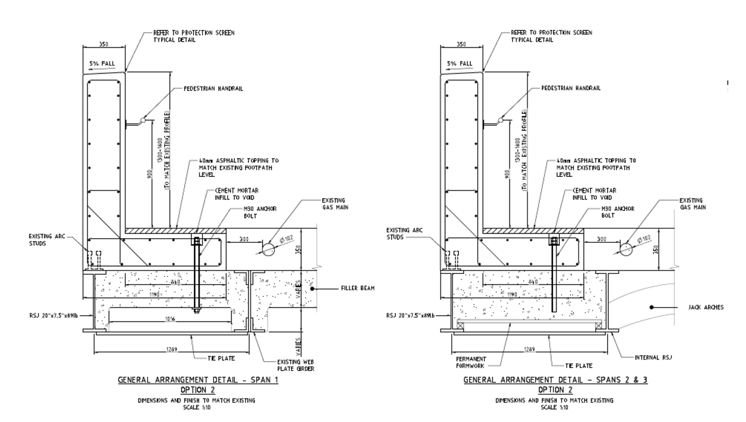
I think the design needs to enable the precast section to span over at least the inside two girders so that shear studs on the top flanges can enable the end section to act compositely and engage more of the deck due to the impact load. This will also mean that we will not have to remove any of the jack arches which will mean we won’t need any temporary works underneath the bridge to protect the tracks and ultimately mean less construction time and distruption due to weekend possessions because we could do all the work from the top. Alternatively I think some for of tie plates will need to be welded onto the bottom flanges to provide the required resistance which means further work to be carrier out from underneath. Providing this additional room for a wider pre cast section to span will result in haing to relocate a number of services (at least the water and gas mains and probably fibre optics to within conduits placed within the precast sections. I think this would still be an easier, safer and quicker way to carry out the works ratehr tahn being afraid to go near the gas main and designing around it which seems to have been the method previously employed.
Someone happened to drive past the site the other week and noticed that all the services within the walkways had been marked out. This would be useful information and I would have had to have employed someone to do this very shortly but it has taken me two days so far without success to try and track down who initiated it so I could get the survey data. The council as well as the asset owner no nothing about it, I have concluded there must a rogue contractor out there armed with a GPR unit locating services around Sydney at will for free!
Any ideas??
To me there seem to be a number of fundamental conflicts that are thematic across the advance sequence during the SCL works that I am eager to hear your collective thoughts on.
Overview
In outline, SCL works in the station caverns focus on widening the 6m tunnels bored by the Tunnel Boring Machine into 10m diameter platform, concourse or cross tunnels. Tunnels are excavated and then rapidly sprayed with concrete to stabilise them and use as the initial lining of the tunnel. See this time lapse to give the idea:
http://www.youtube.com/watch?v=cAWAIwf3nOY
The construction sequence from the method statement is, in basic terms, as follows:
Tunnel Elevation Sketch
1. Excavate top heading to profile, and to 1m chainage. Engineer utilises pre programmed total station to guide plant operator.
2. Initial SCL layer is sprayed to a minimum of 75mm to all exposed ground to seal. Test panel is then sprayed to confirm entry to the exclusion zone in the proximity of freshly sprayed concrete. Using a penetromenter test, a compressive strength of at least 0.5N/mm2 must be verified before personnel enter the exclusion zone.
3. A second top heading of 1m excavated as per point 1. SCL later sprayed in the same way. Critically this means that the engineer, plant operator, nozzlemen and shift geological engineer will move forward into the exclusion zone, and underneath the ‘freshly’ sprayed concrete, albeit not until 0.5N/mm2 is achieved.
4. Spoil in invert removed, and battered to allow access to full profile. Larger tunnels will excavated bench then invert in two stages. SCL sprayed to complete full profile.
NB. This sequence is in basic terms. A number of other activities are conducted pertaining to water management, joint preparation, spoil removal etc. I will not cover these here.
Issues
Three key risks strike me here:
1. Technical.
The spray concrete in the crown of the tunnel is not actually tested for its early age strength. An assumption is made that the concrete on the substrate is behaving as that in the panel. It has been noted by the miners that often the concrete on the wall cures slower than that in the timber test panel (perhaps the clay has a cooling effect, the act of spraying the substrate causes cooling, or indeed the exposed clay is cooler than the ambient temp????)
Penetrometer tests are often conducted in the wall but as it is difficult to reach the crown without getting underneath it, it is not done. As the crown is the last to be sprayed and therefore (probably) the last to cure, this assumption based on the panel strikes mean as not robust?
2. Managerial
Miners are incentivised by a bonus scheme based predominantly on progress. Their base daily salary is around £300 per shift. There is a further £200-£250 bonus if you advance 4m per shift. Any less than that and the bonus is reduced proportionally. Thus the gangs are at full throttle and any reduction in production needs to be a critical requirement or else you will hear about it. Due to the opportunities currently available for qualified miners and nozzlemen, they slightly have the contractor over a barrel here, and if the bonuses were to be reduced or altered, they are likely to go elsewhere.
The shift engineer, from what I can see almost always fits the cliche…young timid graduate who is there to be seen and not heard…but take the rap when it goes wrong. The relationships with the shift pit boss (think grisly SSM) and the lads are limited. The shift patterns are deonflicted meaning that engineers don’t often work with the same gang and therefore their rapport and mutual understanding is limited. It means that it is a significant challenge for the engineer to direct, lead the shift, particularly if he is seeking to slow the rate of advance for say, quality purposes. Its probably fair to say that the engineers are often rushed to keep testing the panel so that the instant 0.5N/mm2 is recorded the advance continues.
3. Health & Safety
Fallout from the crown are relatively regular (very approx 1 per week). Fallout should be reported as a near miss. However, the miners are very wary of reporting these incident, due to its perceived impact on progres for that shift, and any ramifications and blame. Clearly a certain element of discretion has to be exercised, and if the exclusion zone is enforced nobody should be near it. However, it could suggest a wider weakness in the lining.
Solution
I feel that there must be a way of removing the element of assumption from the compressive strength test in the crown, and that the test panel penetrometer need to be augmented with a reliable test that is quick to conduct safely, such that it gets buy in from the guys on site. Having used thermal imaging technology quite extensively in reconnaissance, I though perhaps there is a way of using it here. Having spoken to my line manager it, turns out that there are already products on the market that can test temperature at range, and he was one step ahead of me having arranged a visit from an old mucker of his at Warwick University…a doctor of engineering who has agreed to conduct testing on remote equipment to deliver a TI image of the curing concrete, identify temperature and translate it into an estimate of early age strength in the crown. Im going to get involved in this, with one eye on a TMR, butahead of seeing any results I remain unconvinced. Therefore really keen to hear any inspirational ideas of reducing this risk in the short term that I can cynically take as my own?
The bonus culture, and the fundamental conflict of interest it delivers on site remains an issue. My suggestion of associating the bonus with quality rather than rate of advance was largely dismissed as ‘not what happens…the lads will just find another job’. Not letting this one go…
Keen to hear your thoughts!
USACE – a cultural experience
![]() So what exactly is the United States Army Corps of Engineers (USACE) – it wasn’t what I thought….
So what exactly is the United States Army Corps of Engineers (USACE) – it wasn’t what I thought….
So here’s how things work out here: the following USACE ‘customers’ will submit their engineering demands to the US Congress:
- Any US military installations around the world.
- States that need hydrological works on any of its waterways (these are classified as civil works and include everything from dredging to dam building).
- Federal emergency response services (flood/fire/tornado etc)
Congress will then approve a project, set the budget and hand it over to the USACE in that area to run. The laydown of the USACE can be seen below; my AO falls into the Harrisburg office of Pennsylvania. Escalating upwards on the CoC – 1UP: Baltimore District office (situ in downtown Baltimore), 2UP: North Atlantic Division (situ in New York); 3UP: USACE HQ (Washington DC).
 The majority of USACE construction projects compose of one of the following: (a) ‘Bid, Design, Bid, Build’ type contract i.e. the design process is put out to tender, then the construction is put out to tender, or (b) the design is done in-house by resident USACE architects and engineers (using BIM!!) who then put it out to tender for construction. The USACE do not actually conduct any of the construction – they are the eyes and ears of Congress to ensure that US taxpayers’ money is being spent correctly and that the government construction guidelines and H&S standards are being abided by (which are far more stringent than those outside the gov system).
So why on earth, I ask, would a contractor bid for a government contract when the administrative burden is so high, H&S is so strict, the gov can terminate a contract at a moments notice and you have the USACE keeping you in check at every turn??? Well, simply because payment for work is done by a payment schedule, and once work is approved by the USACE inspector the contractor will have their money in their account from the government within 14 days. If they were outside of government works, payment can apparently take months. Pockets therefore stay flush!
In order that such high standards are delivered, a large amount of SMEs are needed. The Baltimore office alone occupies an entire unmarked 10-storey office block in the central CBD. It is full of everything from archaeologists, GIS wizzes, environmental specialists, tornado trackers, emergency control rooms to lawyers….with only 3 uniformed servicemen (the Comd, Dep Comd…and the Brit!).
On a different note; food is the most talked about subject in the office (a close second to engineering). Recipes are swapped between cubicles (‘cubies’), men vie for bragging rights on their wive’s pancakes, ladies bring in herb-rubs every morning to ‘sniff’ and ‘swap’….I look forward to the upcoming lunch social where a 6 foot (yes – 6 foot) meatball sub will be brought in by an Italian bakery down the road to feed about 20 of us!!! I promise to send you a photo Pete.
Also, the fact that I wear uniform into work brings an interesting dimension to ‘commuting’. Railway ticket conductors stop their work , shake my hand and thank me for my ‘service’, beggars holler the same from across the street, mothers would thank me in shops, old men at petrol stations etc etc…humbling! Even the lady in Subway gives me a free cookie…I’m going have to watch my waistline!
ps The chance of me taking in any photos at this point is nigh on nil unless I clear it through Obama personally – but I’ll try a bit of artistic license to keep in engaging!
