Archive
A Friday Hospital Pass
This week on site the steel fixers have been getting the reinforcement bar ready for the big pour this weekend. So it was hands to the pumps for a 630am start on saturday. Not to happy but a good opportunity to expand my knowledge and collection of concrete photos that only engineering pests would appreciate…Rich I will send you some copies.
The arrival of the diamond core drilling subcontractor on Friday, who I shall call Heath & Robinson caused me a little brain ache and just reminded me of my role and its not to with the guys wielding petrol saws. The issue, during the pouring of the concrete piles that form the shaft perimeter, steel tubes were cast into the pile to allow sonic testers to be lowered into the centre of the pile to test the integrity of the pile and then for inclinometers to be emplaced to monitor ground movement. During the pouring the tubes connections failed and the concrete blocked the tubes so now neither sonic testing or inclinometers may be lowered into the piles. The decision was taken to diamond core the piles to clear the blockage and having had nothing to do with the entire planning of this operation I was suddenly handed a hospital pass yesterday to approve the method statement by this morning. The method statement was sound part from one small detail which was their improvised clutch. The purpose of the clutch is to clamp the diamond cores whilst they further cores are added or removed from the drilling rig.
he proposal was to use a couple of bits of wood and threaded bar to clamp the cores, all seemed fine until I performed a “fag packet calc” (Moran 2013) to determine the vertical load that the improvised clutch had to resist being in the region of 1.5T. Cue the alarm bells!!! Not convinced that two bits of 2”x4” could resist this I decided to panic the men early in order to stall for time and to try and determine if my theory was right. Being the only person in the office who had any idea that timber calcs had many K factors that needed to be considered and that the vertical force we could potentially be facing would have to be resisted by a horizontal force that would need to generate sufficient friction to prevent the diamond cores descending to middle earth, from which I think even Bilbo and his band of merry midgets would have difficulty in retreating them. Quick phone call to Richard in the rear guard to confirm my theory and to gain further guidance and I am now set to carry out the “fag packet calcs” (to follow for those interested.) This whole episode goes to prove another of the great orator’s theories that “you should never assume anyone knows more then you” as they quite clearly don’t. To be continued…
Banana shaped HV substation slab and Beyonce!!
This week did not start well when South West Trains decided to terminate my train at Southampton at 9pm on Sunday evening due to an electrical failure. Having learnt from my last epic 10 hr train journey where a tree landed on the train roof a few weeks ago, I decided to promptly get on the next train back home to Bournemouth as there was no sign of anything going north. The 5am start on Mon to get back set me up well to write a great complaint letter to the train company anyway!
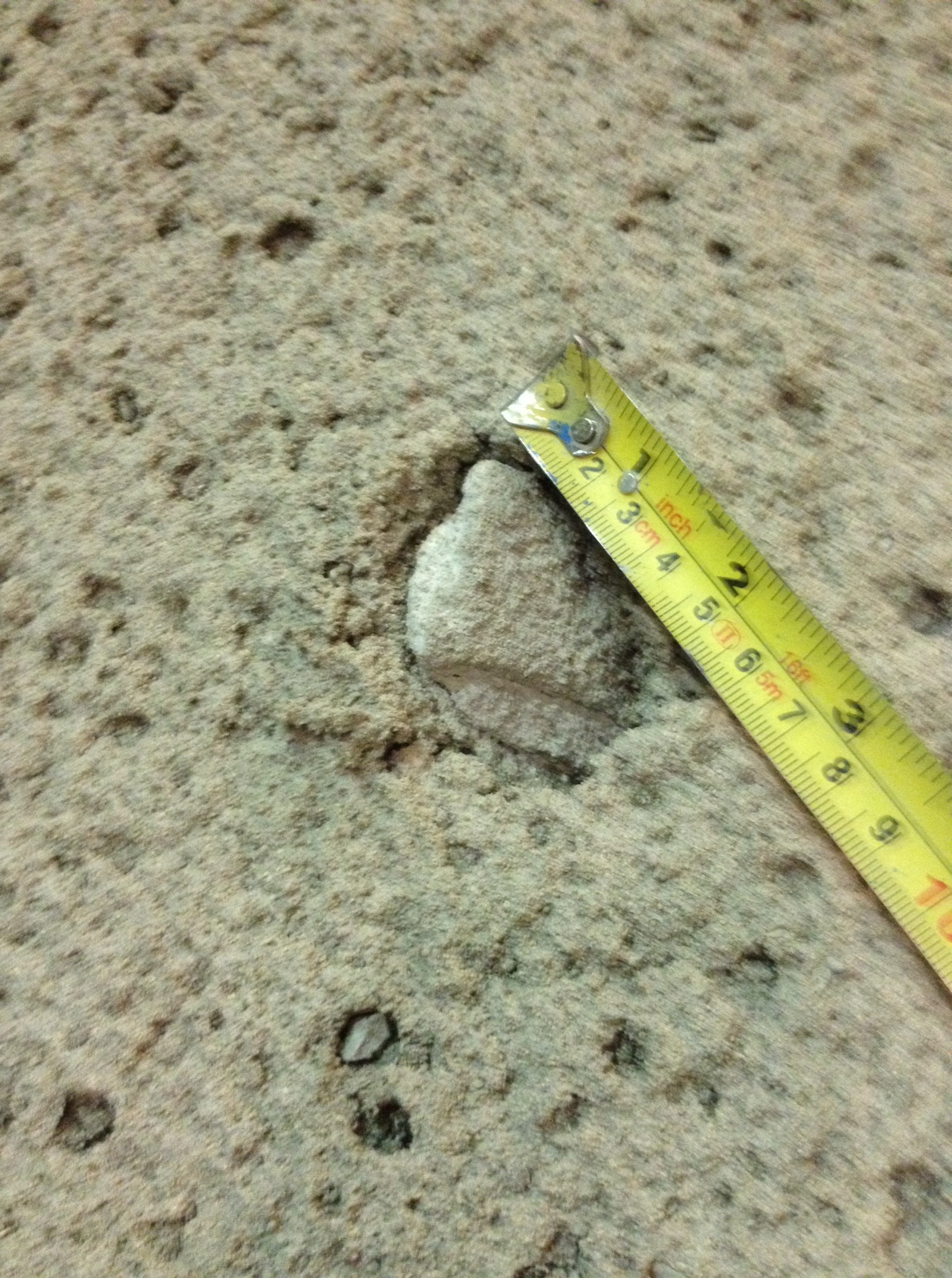
After finally arriving on site the day could have gone one of two ways depending on the progress with the HV substation slab and the tapping of the old pipe. I was happy to find that both tasks had been carried out but when I looked into them further I realised that the day had started at 5am as it meant to go on: a nightmare! Firstly, I went to have a look at my concrete slab and found this:
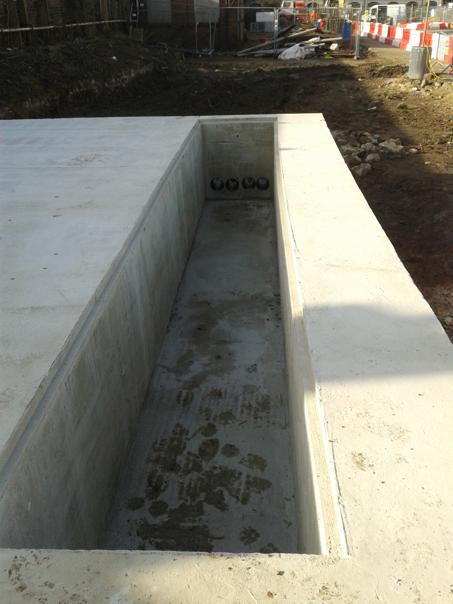
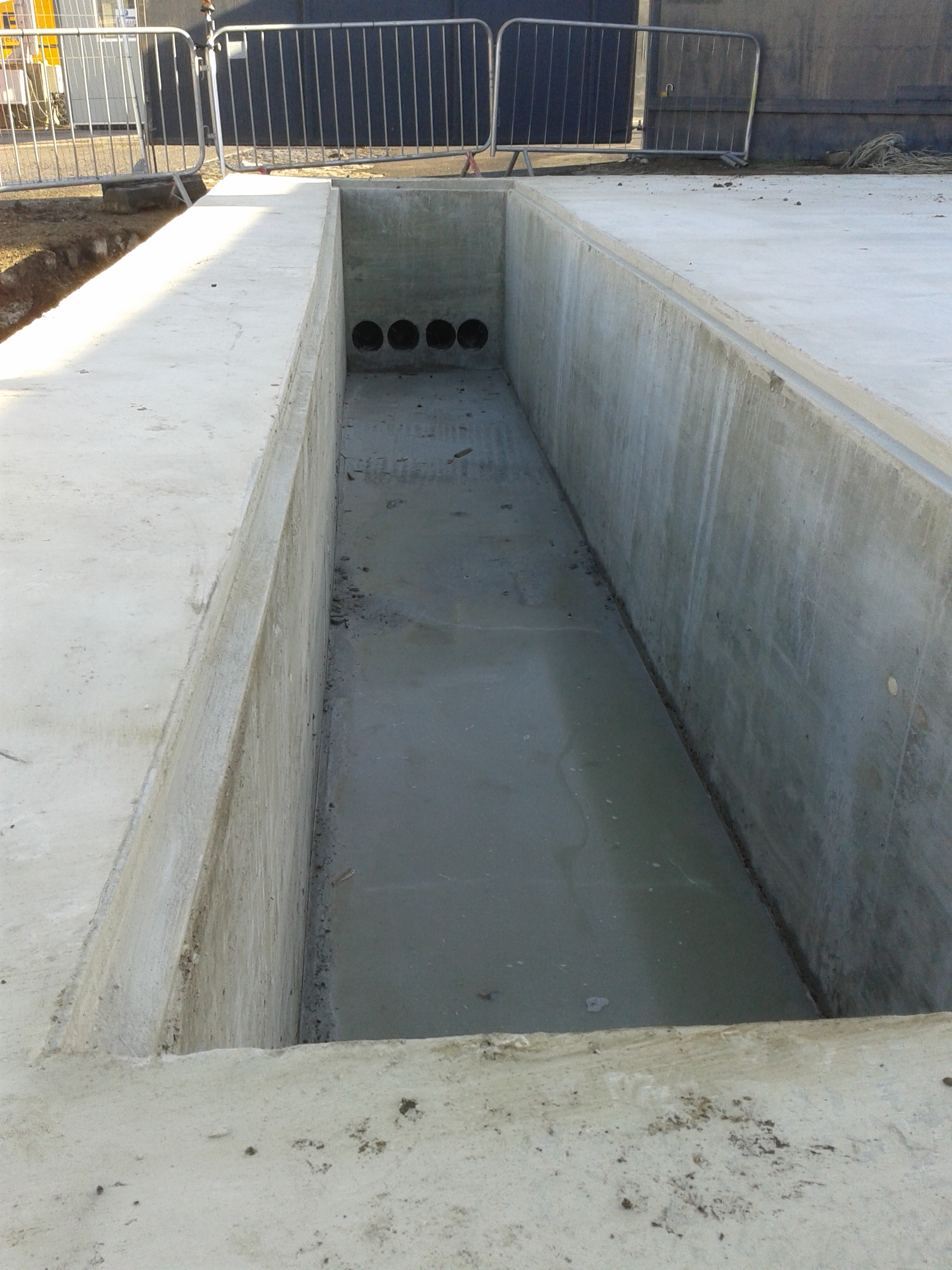
A banana shaped trench that was meant to be straight!! The as built survey showed that the trench was 47mm out about 3/4 of the way along the first picture. Apparently the formwork had got wet before the pour and as a result it had warped or not been strong enough. It is unlikely that the pour rate was too fast for the formwork design as some parts had deflected into the slab. A more likely reason was crap carpentry from the two cowboy builders who won’t be working on site again! The subcontractor may get away with it if the electrical company don’t have a problem with it when they visit next Mon. Otherwise I will be producing a non-conformance report next week for some remedial action to be taken.
Then there was my old pipe that broke the utility guys tapping drill last week. We excavated a straight part of the pipe and they were finally able to tap it and it was found to be an old gas pipe, not full of gas but full of water. The drainage gang took the bung off and spent an afternoon letting it drain and pumping out the water. A few hours later they gave up as it didn’t seem to be draining-back to the drawing board! Plan B involved hiring in a water tanker pump vehicle to hopefully pump it out. 2000 litres and 2 tankers later they were finally in a position to break the pipe and carry on. The south drainage area has now been nick named the aquatic area and they will have more problems to come when they encounter the run-off from the wheel wash that is also turning part of the site into a swimming pool.
![20140306_112718[1]](https://pewpetblog.com/wp-content/uploads/2014/03/20140306_1127181.jpg)
![20140306_112727[1]](https://pewpetblog.com/wp-content/uploads/2014/03/20140306_1127271.jpg)
The week ended in a slightly more positive note with a free trip to the Beyoncé concert at the O2 arena. Our groundworks sub-contractor’s O’Keefe own a box there so they invited the construction team for a night out. With free drinks and food and a great view it was a great night out. However I have learnt that drinking on a school night isn’t much fun when you get given a list of RFIs to check if they are closed the next morning!
![20140306_214431[1]](https://pewpetblog.com/wp-content/uploads/2014/03/20140306_2144311.jpg)
I Feel Dirty
Today I genuinely enjoyed the construction of a spreadsheet, this is probably the day I’ve enjoyed more than any other since I’ve been here at Ramboll.
The Problem
We are part of a team tendering for a new large 1 km ish bridge over a river on my mudstone. I have been asked to look at the West Tower which is a spread foundation on the mudstone that is currently sloping quite severely and has a minor road at the top of that slope. The mudstone has discontinuities although orientations aren’t known. I was asked to identify whether there are any orientations that are particularly dangerous to the foundation.
Direction
Initially I was told to us Slope/W which is a simple program that can check large numbers of slip surfaces on a slope in a short time and come out with the least safe. In order to model the rock with discontinuities I was advised to model the discontinuities as regions with weaker parameters to encourage failure along these lines. It all made sense so I started learning Slope/W and built a model.
Issues
After running a few iterations of the model and speaking to the person who first tasked me it became obvious that things weren’t so clear cut. The model didn’t seem sensitive to the properties of the discontinuities, I even gave them the friction angle of ice cream and it still didn’t fail along them. Going back to original instruction revealed that she didn’t necessarily know how to get it to work, or even what the answer might look like (I can hear the Orator as I type if you don’t know the answer don’t use a program! I would be fairly unemployable right now if I stuck to that advice). She then promptly buggered off and after a day or two of wrestling with stupid answers spoke to the Director who had tasked the other engineer, he was equally confused but gave me a book on Foundation on Rock (along with a quip about when he was looking for it on Amazon all that kept coming up was music related, hilarious).
Stability of a wedge
The book was quite useful and gave examples of calculating the stability of a wedge based on certain soil parameters and geometries of rock and loadings. Because we didn’t really know the orientation of the cracks and that my brief was kind of a what if analysis I decided to stick it all into excel and see if I could make it work. This is why I feel dirty, I had to design the spreadsheet on paper to make sure I got all the variables, lots of coordinate geometry and learning to use ‘data tables’ with 2 variables later I churn out a table that will autocalculate the lowest factor of safety depending on crack angle and the point at which is intercepts the front of the slope. I can then fiddle with discontinuity parameters such as friction angle or rock unit weight or applied load and see how it changes the FOS. Next week I will interrogate a true expert on Slope/W to see if they can get better answers on the problem.
What have I learnt?
- Software can be limited – There were issued modelling the surcharge in Slope/W because it was below the level of the ground so I had to model a rock with a unit weight of 2200 kN/m3
- Books are useful
- Clear briefing is a skill that isn’t necessarily easy to find in an office, this relates to other stuff I’ve put on here over the last month or so that designers don’t get the opportunity to really manage, I’ve just had things thrown at me a couple of times and been expected to get on with it with little to no brief
Other recent lessons
- People will just assume you can read your mind, or they don’t know what they really want when the task you. An individual from another office working in structures wanted some pile group modelling done but didn’t explain how he wanted the output so the work took twice as long as necessary
- Geotechnics is about experience and experience, knowing where to look for the answers and best guesses are the currency. We are looking at doing an extension to a quay wall in a dock basin that can’t be drained and need to know what angle the mudstone can’t be excavated to and remain stable, the answer is ‘who knows? But our best guess is ….’
- When you tell people what you’re doing and that you’re going to CPR in Jul they all reply sceptically ‘That’s a bit fast isn’t it?’ they are promptly silenced when politely informed that the Army allows you to cover all the DOs they can’t in a design role. As an illustration a Resource Leader (read just below executive board level) gave a Business Update presentation the other day and I have genuinely seen Sappers do a better job.
My tunnel is too tight….
One thing that has struck me since joining CrossRail is that the opportunities for innuendo bingo are legion. I will not recount the most memerable examples here, but I encourage you through the medium of my blog to play along at home.
So after almost two weeks held in reserve, up in the main office at Hanover Square, I was unleashed on an unsuspecting site at Tottenham Court Road. Now I would like to think that coach put me in due to my obvious concrete competancy, but I fear it was much to do with a calender clash that distracted almost everyone else on the team. Turns out Friday, was the annual Concrete Society Dinner…a social event only just overshadowed by the Oscars this weekend….
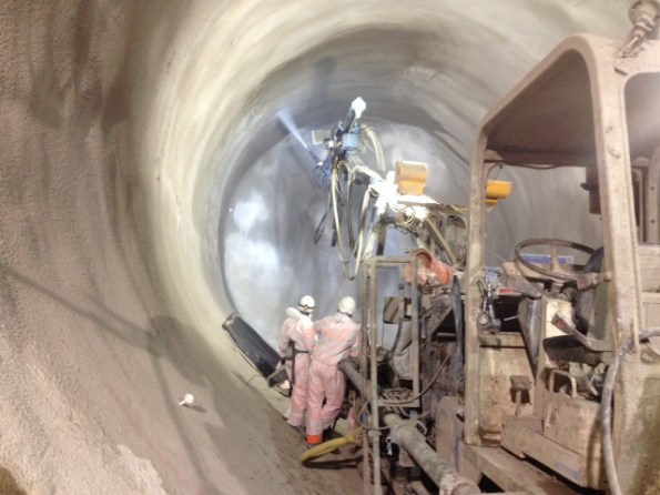
The running tunnels, cross passages and concourses have all received their initial and primary sprayed concrete layers. Initial lining is utilised to protect and prime the excavated surface and is sprayed to thickness of approx 75mm. The primary layer contains steel fibre reinforcement and provides the main structural integrity of the tunnel, and runs to a thickness of 450mm. Following that, the surface requires regulation and preparation in order to cover rogure steel fibres that are likely to damage the subsequent waterproofing layer. This is acheived by spraying a finer aggregate layer. Or so we thought…..
I stepped in to take over the workss which had been programmed and planned…allegedly. Predictably I arrived at site to find that nobody down there had been briefed and the concrete hadnt been ordered! Difficult to spray concrete, I find, without, er, concrete…
After many an hour listening to a load of Irishmen shouting at each other we finally began to spray. The Potenza spray machine…essentially a large hose mounted on a pickup truck, which allows regulation of flow rate. This brings about a quality management point. The nozzlemen…Spr Bloggs as we would know him…want to spray at the max rate of 20-22m3/hr. He gets a bonus per advance/chainage completed in his shift. Understandable. However, this flow rate increases the chances of rebound. Exactly as it sounds, the concrete does not adhere readily to the substrate causing dimished strength.
This brings about a quality management point. The nozzlemen…Spr Bloggs as we would know him…want to spray at the max rate of 20-22m3/hr. He gets a bonus per advance/chainage completed in his shift. Understandable. However, this flow rate increases the chances of rebound. Exactly as it sounds, the concrete does not adhere readily to the substrate causing dimished strength. Test panels that are sprayed, then cut into beams, highlight band layers which reduce the flexural strength by creating failure plains
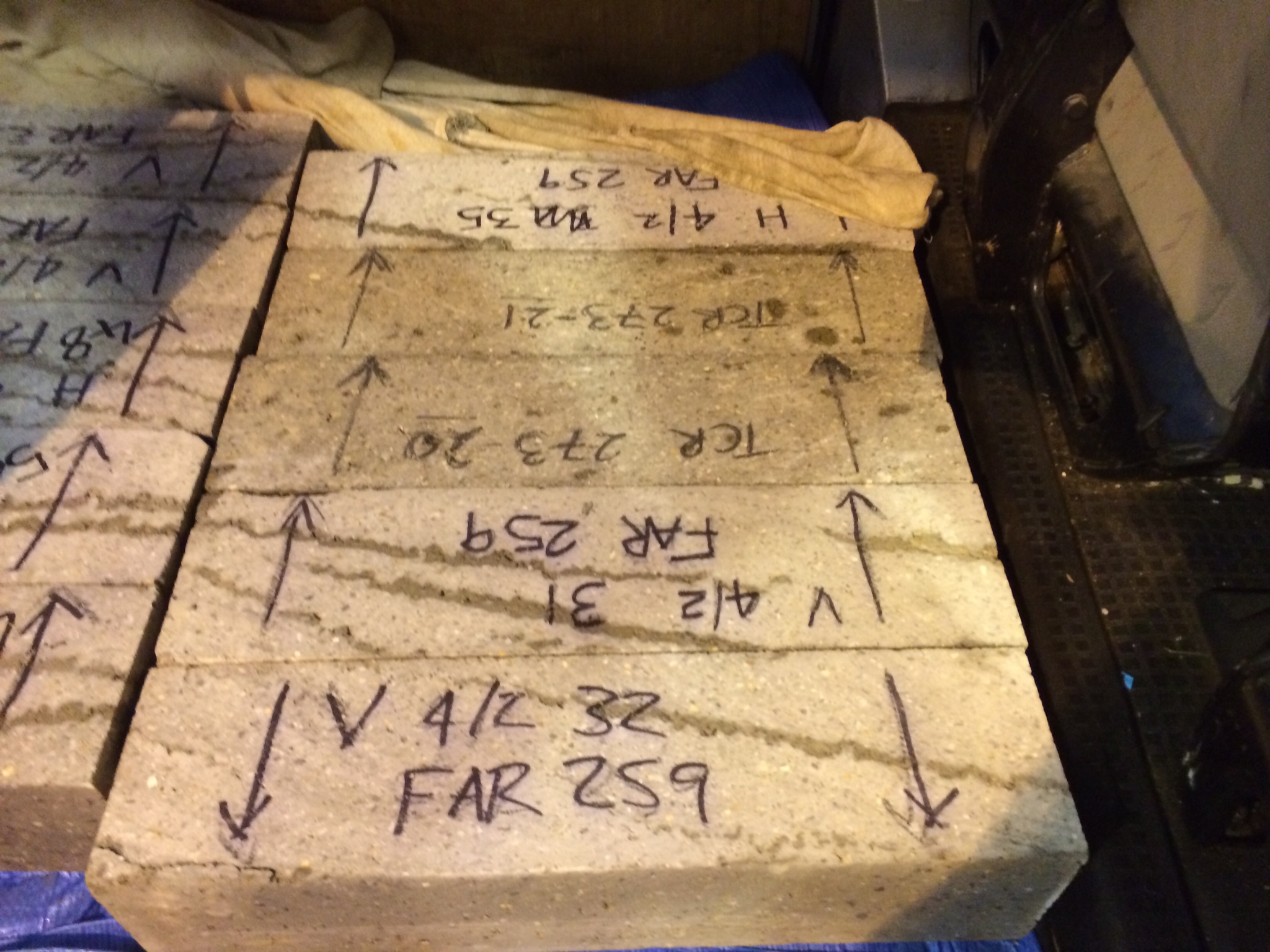
Note: TCR=Tottenham Court Road, no band layers. Far = Farringdon, band layers. Inconsistent quality assurance across sites is future blog fodder…look forward to that!
On completion of the regulating layer spraying, I returned to inspect. It was immediately clear that things hadnt gone well. The surface was particularly poor, and contained craters caused by large aggregate. The reg layer is supposed to be a finer aggregate so it was immediately clear that there was an issue with the batch

After some digging, a number of issues came to light surrounding the concrete contractor, Hanson.
1. The core contractual terms dictate that when concrete is ordered from site, it must be batched within 50mins and sent immediately to site, where the lorry is tracked. However, this does not apply to concrete used for trial which is outwith of the core contract meaning the contractor can effectively send it when he’s ready. Over six hours later in this case. When our first batch arrived at site, it was flow tested and failed arguably due to too long in the wagon.
2. Quality control. It seems that the batches were contaminated at the plant with a larger aggregate, whihc presently is unexplained. From our perspective this is frustrating. The mistake has managed to creep past the initial batcher, aswell as our liason guy at the plant (whose job is precisilt designed to prevent this!). Additionally, when it was receipted on site and tested (temp and flow) it was again not picked up.
As a lessons learnt, we will now have an SCL rep on the surface to oversee receipt of the batch. When a sample is taken, it will be poured into a bucket through a sieve as an additional check to confirm aggregate size.
Next up are the trials of the waterproofing layer, which is entirely my baby. I wrote and admin instruction and distributed it yesterday with a number of taskers. Its raised a number of eyebrows, as it doesnt seem to be the done thing to communicate with each other around here. Granted, due to my poor understanding of the hierarchy, I did effectively task CrossRails Chief of Staff! How to win friends etc….
I designed something
It has been a few weeks since my last blog largely because I have found it hard to bring myself to again ‘tippy tap’ away on a keyboard following the delightful months of Jan and Feb report/thesis writing. Since my last blog I have gotten very little sleep because I believe my child may be possessed by the devil between the hours of 2000-0700 hrs but I have also done a few proposals and some designing finally!
Proposals/Tenders
Since starting I have been given two proposals, one for TfNSW (Transport for New South Wales) – yes the name is probably copied from London – and one for Sydney Trains. Sydney Trains are actually a entity of TfNSW but becasue they are the train service operators they do have a slightly different approach and format to proposals than if it were a new TfNSW project. Both have exposed me to the way proposals and the important lump sum fee is derived which I covered last time. Becasue I have managed both of these proposals I will PM both if we end up winning them but at present nothing has been heard which is probably not a good sign. Subsequently I am slowly being drip fed other proposals as they come up and have just completed a design services fee for a multi-storey car for an architect who has been approached by a tendering contractor for a TfNSW Design & Construct (D&C) contract. I only had a day to do this but the architect has had the proposal for a month which suggests they have probably given it out to other consultants and receievd rather shocking prices back or just wanted a fee to compare previous quotes to. Either way they seem to like it becasue another proposal came my way this morning for a similar car park – I may get branded “the car park guy” very soon! I think I covered pricing details in my last blog, needless to say it is not very scientific and involves just estimating the amount of hours you think it will take across the multiple diciplines to achieve the specified deliverables as set out by the client. The design stages seem to get named differently depending on the client but generally follow this sequence; System Definition Report (SDR (concept) – 15%) stage, Preliminarry Design Report (PDR – 50%) stage, Critical Design Report (CDR (detailed) – 90%) and then Approved For Construction (AFC) stage. Between each stage there is a least a 2-4 week review procedure with the client to get through which can take longer and is why many sub-consultants are very wary of the smaller jobs as the margins are tiny and in this business time is definitely money. Everyones hours are acconted for against a project number and every job I have come across seems to be a lump sum price. The final parts of the design stage are often in the form of construction support (answering Request For Information’s (RFI’s)) and of course As-Built or Work As Executed (WAE) documentation and drawings which formally records the changes to the original design throughout the construction process as well as confirming that the the contract has been fulfilled by the Contractor.
Eveleigh Columns
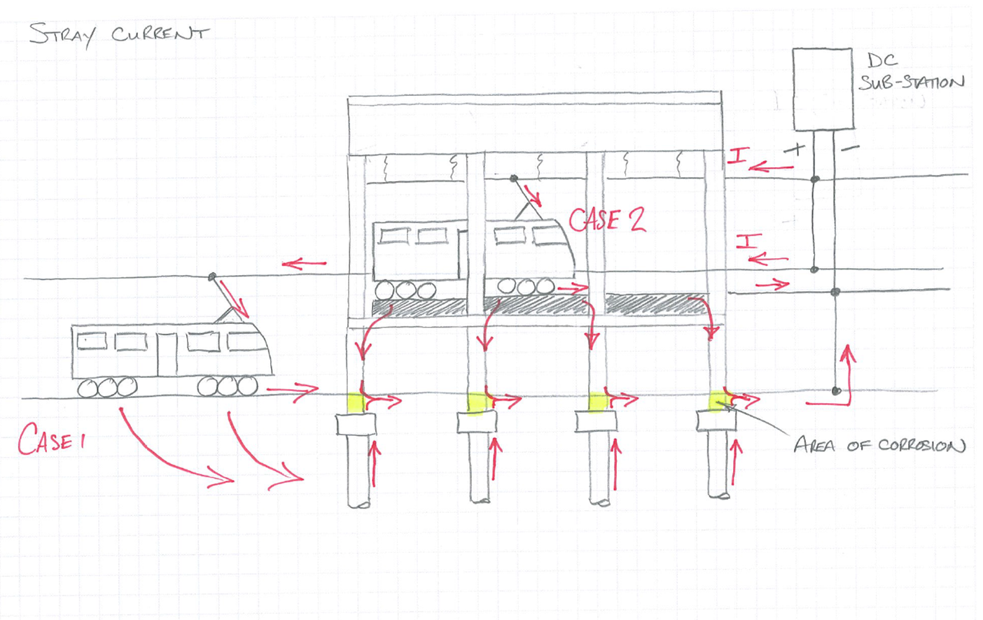
The Eveleigh MC column deterioration due to corrosion has now progressed and I have produced a reference design for the client so that a Design & Construct contract tender can be issued. As I mentioned before, it was believed that stray traction current may have been causing the corrosion. I also remember the great orator may have asked a few questions which I will endeavour to answer here. Firstly the concrete strength that I used as the basis for the original structural capcity check was low due to the variable results of core testing, I did not use a strength 1.64 dev below a mean value, I used the following equation from the Australian Standard which equates a characteristic value of a sample by taking away the (sdev of the sample x an S value) from the average. Secondly, the thought regarding the mechanism of electrolysis taking place was due to the current from the OHW finding its way back to the substation via one or both of the tracks and that the building was parallel to the tracks and I assume that the substation is also within close proximity of the building, then stray current was being conducted through the piles and columns, again I assume because this was a shorter path for the current to take therfore the reinforcemnet was acting as a cathode with the ground and the ground and piles acting as the electrolyte. In this example there is also a second case to support the stray current theory and the more likely, this is due to the OHW and tracks within the building with the current travelling down the raised track supports and through the columns in the basement to the ground. There is a couple of sketches below to try to explain this a little better or confuse you even more!

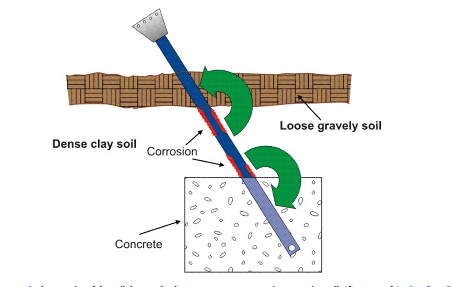
We ended up getting a sub-contrator in to measure any current flow within the columns and concluded in the end that stray current is very unlikely to be the main cause of corrosion. The fact that there is no ground slab, the basement has poor ventilation and is very hudid, as well as the quality of concrete and lack of adequate cover in places suggests these issues have accelerated carbonation attack of the concrete to the depth of the reinforcement. Chloride attack has also been ruled out from ground testing. Although it wasn’t in my scope of work I wanted to investigate the mechanism of the corrosion further which resulted in me involving other people who after a while wanted the project number to charge their time too, which was probably not expected by my manager. I think because the client has had little idea about what they want this has been a job that SMEC want to close out and move on from quickly. My investigation has determined that the likely cause is from a differential aeration corrosion cell formed between the two environments with which the column sits i.e the ground and humid basement area, coupled with poor quality porous concrete. Oxygen not only enables a corrosion reaction by maintaining a cathodic reaction, but it can promote one. This occurs where there is a difference in the
concentration of dissolved oxygen between two points of the same metal surface. Hence the poor quality of concrete has enabled oxygen to contact the reinforcement steel. The below diagram explans how a differential aeration cell works, the portion of the shaft in contact with the clay type soil acts as an anode to the portion of the shaft in contact with the looser gravely soil, which is consequently the cathode. This can be thought of as a similar scenario to the columns where differences in porosity can lead to an oxygen concentration corrosion cell:
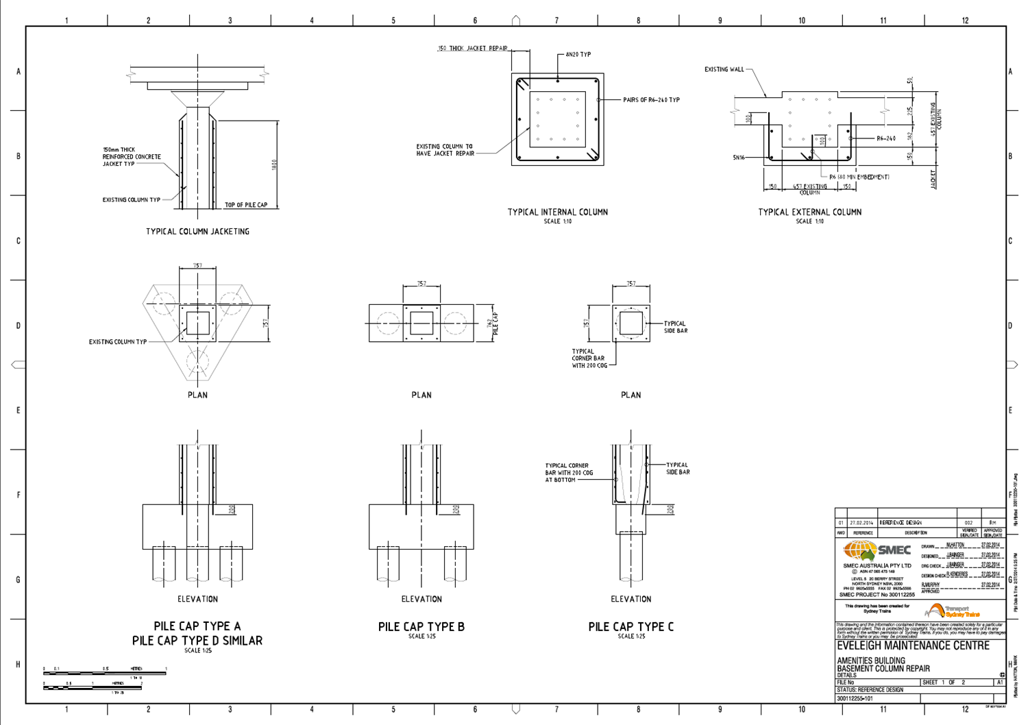
The CP option has now been discarded and the client wanted a worked up design for the repair of the columns so that they can engage contractors to price and execute the work. My solution was dependent on the severity of corrosion within the columns which we will not know until a contractor is elected to carry out the work. I then looked into treatment and patching products. I ended up modelling different levels of corrosion depending on what may be found by the initial investigation by the contrator which would then trigger a particular repair option of either localised patching or constructing a RC jacket around the column. I determined that up to 15% reinforcement section loss on either a corner or single face could be accepted before a jacket would have to be constructed, this was based on providing a further 50 year design life to the structure. An even, overall section loss throughout the column of 40% would also be acceptable but is highly unikely to occur. Any reinforcement section loss above these levels would require a jacket of concrete to be constructed around the column(s). I also had to think about the methodology and sequence of works. Having a better understanding of a contractor it would be a fair to assume they would start hacking out concrete that probably doesn’t need to be removed and more importantly would affect the structural integrity of the whole building, certainly if multiple columns are repaired simultaneously. This required a Safety In Design (SID) process to be carried out, which is pretty much just a risk assessment tool which identifies the main hazards and controls as well as the residual risk post control. In this case, measures such as temporary propping in some circumstances but prodominantly trying to eliminate the risk by only allowing a specific sequence of work to take place, so that sufficient redundancy remains within the building and ensuring the building loads do not increase – the use of the building does not change throughout the works. Below is the drawing that – along with a page of notes – accompanied the design report and performance specification (methodology):
It is a good idea to hit steel to steel connection bolts with a (small) hammer
So here is a picture of Tower Crane Two (TC2). It is a WOLFF tower crane with a 45m tower and a 40m jib.
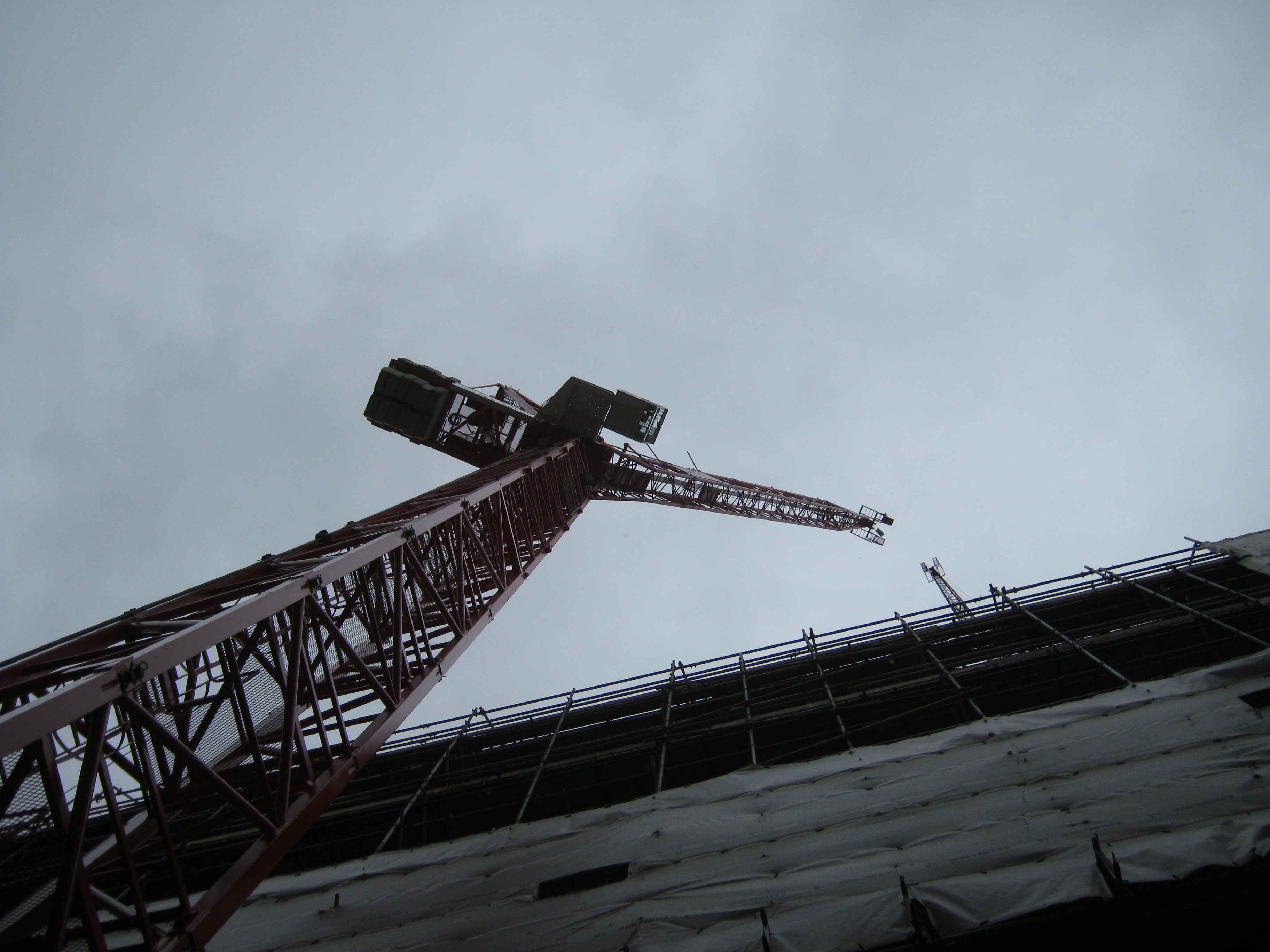 Tall Red Crane
It was installed on Thursday and Friday last week by HTC. On Thursday morning prior to the installation I went on site with Roy (the Mace Construction Engineer) and the designer (from a consulting engineers) to sign off the grillage.
The steel grillage connects the tower crane to the piled foundations beneath. Simple right? That is what I thought. So we went on site, had a look at it and signed the paperwork after some discussion.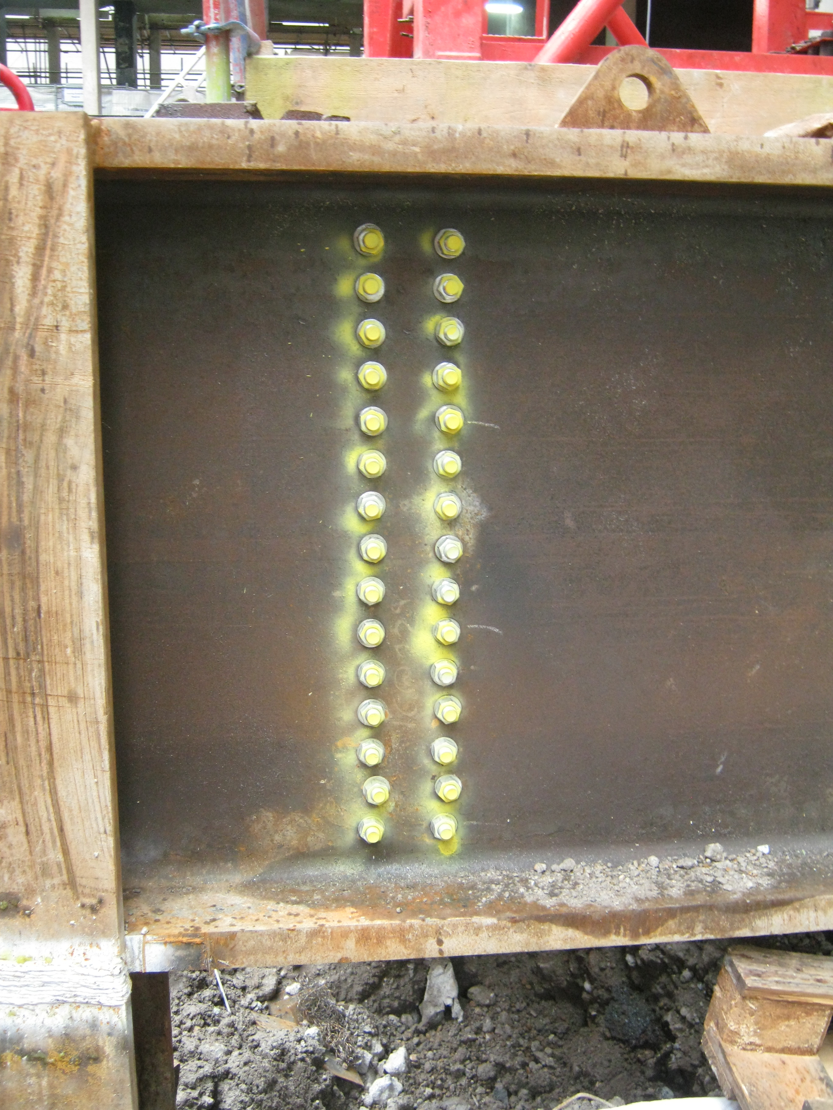
The Grillage
Well on Friday afternoon with the crane built and the load test about to start, the HTC inspector just thought he would check the bolts on the grillage (sprayed yellow in the picture above). Technically doing this was not in his remit, but he thought it wise to give them a tap with a hammer to see if they’d ‘ring’ (tight) or see whether they were loose (and don’t ring).
Well, many didn’t ‘ring’! In fact maybe 5-10 (of 240) were positively loose and perhaps 50% could be tightened further with a long spanner! Queue phone calls to the Construction Manager, Sub Contractors and me! The questions being:
1 Why are the bolts loose?
2. Who tightened the bolts?
3. What torque should they be?
4. Who signed off the grillage?
Since Roy was not in the office I found myself answering these questions. It turns out the answers were:
1. They were not checked, or re-checked.
2. The sub contractor PC Harrington responsible for the grillage sub-contracted the fabrication to DAM Fabricators. DAM didn’t check the bolts.
3. There is no torque. They had to be tight (manufacturers guidelines)! I think this means a man/woman hanging off of a spanner. As I understand it only friction bolts usually need a torque.
4. PC Harrington, Mace Construction Engineer, the Lifting Operation Manager for Mace.
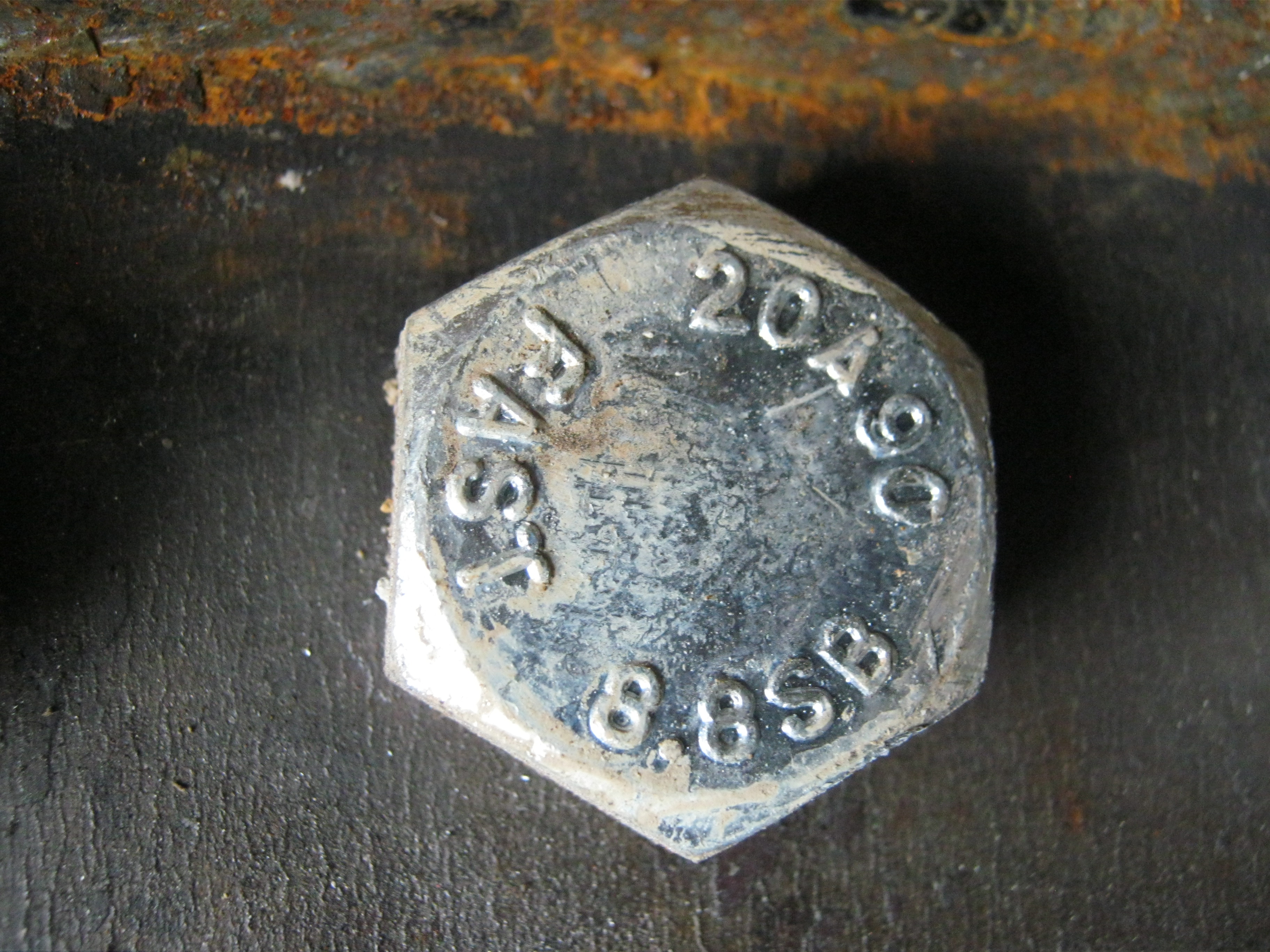
The bolts in question
So what is there to learn? All sub-contractors need to sign off their work (DAM were responsible for the bolts and they had no sign off directly to Mace); Sub-contractors need close supervision (no surprise there); Hit bolts with a hammer to get an idea of how tight they are; And finally understand what checking procedure has been used prior to you checking something.
Have I missed anything???
The key question I haven’t answered to myself is whether we (Mace) should have done a random check of bolt tightness? You chould say yes, but then we’d have a lot of other bolts to check too. I guess it’s all about the risk associated with that particular bolted connection!!!
Quick the HSE are coming-go and paint that mud brown….
….wait no, paint any undulating piece of ground yellow just in case you might trip over it!!
The first half of this week was spent making sure you could walk round the site blindfolded without tripping over, getting hit by a piling rig, falling in a hole or snort asbestos. The HSE were coming to visit on Wed morning and it resembled a visit from the CGS or the Queen. On Mon we had a management walk around with our H&S Advisor to pick up on a list of improvement points which were mostly just site tidiness and pedestrian segregation. For such a big but also constrained site it wasn’t too bad.
I finally got my fence moved 3m and the GPR Survey team arrived to survey as much of the embankment as they could. This week I was able to get them in the gate I wanted to and I even organised somewhere for them to park which was an improvement on last week’s fiasco. We also made some progress with the second mystery pipe however not as much as we hoped. The Carillion Utilities team came out to tap the pipe on Thursday so on Wed afternoon I requested the contractors uncover a straight part of the pipe. Unfortunately they encountered a second bend and then ran out of trench box to dig further. The utilities guys decided to have a go at tapping it anyway but in the process they broke their drill! So that left us with a mystery pipe with the start of a hole in it, 6m down in a trench box, 3m away from the Network Rail fence and 1m from our access road. Why are things never easy? Hopefully tomorrow I will find out that they fixed their drill and came back on Sat to show that it was empty?
I am also in a similar position to Rich Hall working for the management contractors rather than the sub-contractors on the coal-face. At first I thought the closest I was getting to technical engineering was building my Ikea bookcase and installing mud-guards to my commuting bike. However I have taken on the role of being the Section Engineer in charge of utilities and the Network Rail Access Road and I am now starting to ‘identify and solve engineering problems’. I have already found a problem with my second HV substation and I will probably write more about that the end of this week. My role also includes checking Risk Assessments and Method Statements (RAMS) and Inspection and Test Plans (ITPs). Again I feel a bit like the Sqn 2IC who is collecting and checking the Troopy’s paperwork and regularly inspecting their work on the ground. I was due to sign off and inspect the HV substation during the pre-pour checks on Fri afternoon but they weren’t ready in time and I had to catch my lift to Bedford to finally rescue my van from the garage it had been at for 2 months. Hopefully I will get to do the other concrete pour next week. I am also planning on spending a bit of time on the ground with the sub-contractor’s engineers to do more of the detailed engineering on the ground.
This week I did have another ‘debate’ with the site management company about whether I was working on their land or not. This time they told me that we needed to make part of it a pedestrian walkway even though that was what they stopped me doing last week. Apparently it is clearly on the drawing that I have never seen before! I can see I am going to have some fun over land management! One of them also advised me that I needed to keep an eye on the contractors working safely. He pointed out that there were no mushroom caps on the protruding parts of the clamps holding the formwork together even though the guys were still building it. He also said that there should be edge protection on the shuttering as they were climbing onto the 1.2m high formwork whilst still building it. How on earth you are meant to edge protect something so low I am not sure and seeing as falling from it wasn’t in the RAMS I don’t think anyone saw it as a risk. In my eyes they were not doing anything wrong or putting themselves in danger so without covering every labourer in cotton wool or body armour I am not sure how far we are meant to go! I am now slightly concerned with my approach to digging up the tree trunk in my garden, I might install edge protection to the 50cm excavation (that is battered to a safe angle) to ensure that the neighbours cat doesn’t fall in over the week!!
Far too many documents
The last week or so has mainly been filled with finishing the Driven Piling Procedure for submission and buying thermocouples, data loggers and some formwork for large concrete test cubes. I’ve also had the joy of starting the Concrete Process Procedure and concurrently starting to write the Activity Method Statement (AMS) for the piling.
You may think that the piling procedure and method statement would be the same document, sadly they are not. The first one is submitted to the client for approval as it contains the “How we will do it” for a number of the piling activities that need to be approved in advance. For example the piling procedure (that I would think of as a method statement) must be submitted for approval a minimum of 21 days prior to starting piling. The second document is internal to John Holland and mainly covers the risk involved in the task, broken down into three areas: Quality, Safety and Environment. Its safe to say that I have been hassling the piling sub-contractor a lot for his intended methods and then changing them based on my vast knowledge gained from many years in the piling industry….or not. As it happens I had to alter his process to fit in the pile testing procedures, and there is likely to be a fair bit of waiting on site for the first hold point to be released (CAPWAP analysis needs to be completed before we can continue piling and the client needs to sign off on it).
I’ve also finished the projected program of works for bridge 1 for the next 3 weeks in detail, with the next step being planning out for the next 3 months. I’ve got one wee graduate engineer working for me and should have another 2 starting around mid March. I guess that’s D.O. C3 sorted. I think I’ll need them by then as the date for the first pile in the ground is fast approaching, and then the first concrete pour (pile cap on pier 3) is only a week after that.
I also had the (dis)pleasure of becoming more involved with the contracts side of things. My main focus is the JHG contract with the piling subcontractor (Caporn Piling), but I’ve also looked into the highly interesting tome that is the main contract with the Client (Qld Main Roads and Bridges). I can now see the advantages of the NEC 3 contract with its relatively limited use of “legal speak”. The contract is build only, with payment by instalments. Each month we submit the work lots that have been completed along with supporting evidence, and the client pays that amount. When tendering for the main contract it was a pretty quick process, there was no to and fro in making changes to this clause or that, it’s a simple take it as the government body sets it or don’t bother bidding. (I think JHG did submit a list of changes to Main Roads, but were told it’s a flat out no) I see the thinking behind levelling the playing field and avoiding any possible claims from losing bids (thinking back to Virgin Trains losing the west coast mainline contract and their subsequent legal challenge). In addition all bids had to submit conforming designs as per the tender documents, alternatives could only be submitted along with a conforming design. Any bids that submitted an alternative design only were dropped and did not proceed any further in the tender process.
From the clients point of view this is very good, all the roads and bridges in Queensland will be built to the same spec, reducing complexity and future maintenance costs. The downside for JHG as the main contractor is it is very difficult to find areas to make savings (and so increase the profit). To say the budget is tight would be an understatement (“tighter than a ducks arse” springs to mind). There is more to say on the supplementary specs and annexures, but I’ll save that for AER1.
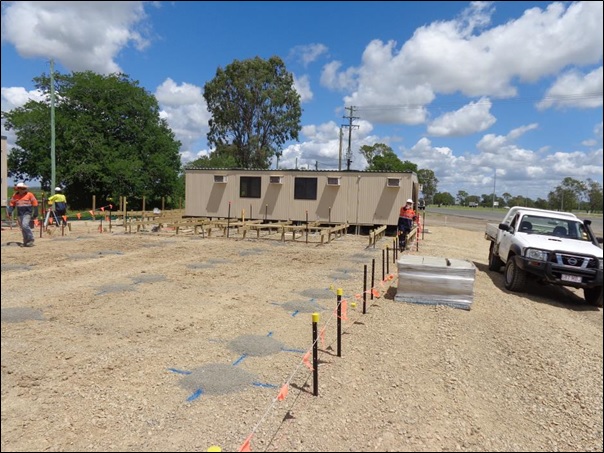
Oh, and the site office is finally going in so I should have somewhere to hide from the sun when I arrive next week.
In other news I went to Australia Zoo, so here is a photo I took of a tiger yawning.