Strong as a Kit Kat – Part 2
The last blog saw me trying to understand the issues surrounding the high failure rate in the concrete in the primary lining, with respect to flexural strength. In a pincer movement reminiscent of the Zulus at Rorke’s Drift, Richard and John exposed my mild bluffing surrounding the testing procedure….
So here is me attempting to be John Chard…
Why test for flexural strength?
Concrete is a brittle material with a low tensile strength. Adding steel fibres to the mix will enhance toughness and ductility defined by the BS as follows:
Toughness – the ability of fibre reinforced concrete to sustain loads after cracking of the concrete ie its energy absorption capacity
Ductility – general ability of the material to sustain load beyond a yield point that defines the limit of elastic behaviour (onset of cracking). (Concrete without reinforcement would be brittle and demonstrate an abrupt loss of strength beyond elastic range.
The sprayed concrete that delivers the structural propeties of the tunnels is steel fibre reinforced (SFR).This ensures that the structure is able to sustain significant ground movements without sudden brittle failure. Therefore the trials procedures will seek to test the ‘Residual Flexural Strength’ ie the flexural tensile strength retained after cracking.
Testing
The CrossRail specification for Sprayed Concrete Linings specifies BS EN 14651 as the test method for approving:
1. Flexural Strength
2. Residual Flexural Strength
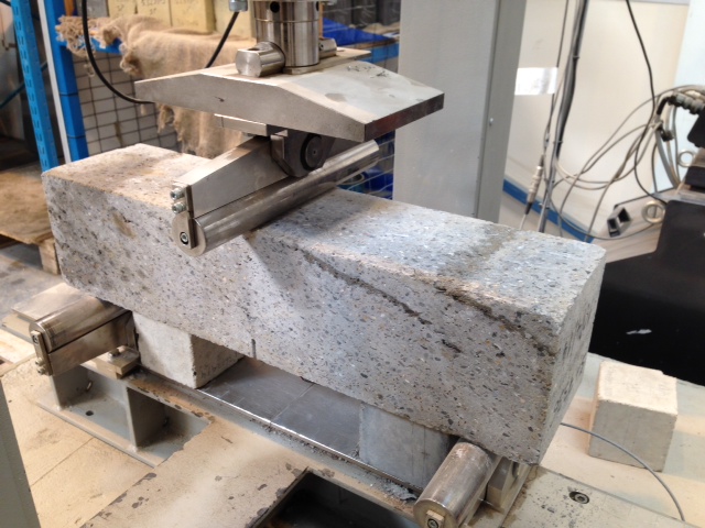
The test beams are centrally loaded as shown below, by the 3 point method. The specimens are notched at mid span to induce a crack via stress raising
Performance of the test sample is specified by the relationship between the applied load and the Crack Mouth Opening Displacement (CMOD). This measurement can either be measured directly, or calculated in terms of central deflection
Measurements are taken as follows:
F(L) is the load corresponding to the limit of proportionality (LOP)
F1 @ CMOD1 = 0.5mm
F2 @ CMOD2 = 1.5mm
F3 @ CMOD3 = 2.5mm
F4 @ CMOD4 = 3.5mm
The slide shows a typical graph of load, F, against CMOD (BSEN 14651:2005)
Flexural Beam Test Correlation
Flexural Strength
f(L) is calculated in terms of the centre span load, F(L) as follows:
f(L) = 3FL/2bh
h = depth of beam above the notch
b = section width
L = span
Residual Flexural Strength
Crossrails specification tests values of residual flexural strength @ deflections of 1mm and 4mm respectively. However, this is not measured directly, and is measured as a CMOD, which adds an approximation to the calculation (I’ve asked the test centre why they do this…awaiting response). At these values, the beam must retain values of 1.8 and 1.4 respectively.
REFLECTIONS
1. CMOD v Deflection. Other than reliability of measurement, I dont know why CMOD would be used over direct deflection measurement (yet). Whatever the reason, the approximation adds a level of uncertainty that we can ill afford. The example test result above shows a beam which has failed, by a tiny amount, and which is typical of many of the beam failures. Perhaps a wider understanding of this testing method may mean that a tolerance is imposed such that this group of slim failures may edge over the line and achieve a pass?
2. Testing Method. Prompted by the Great Orator, I considered the 3 point testing method as discussed above. This method implies a failure method of coexistent shear and bending. 4 point testing methods for pure bending are specified in the EFNARC beam test (European Federation of Producers and Applicators of Specialist Products for Structures). The BS EN 14488 beam test largely adopts this method, and is mentioned in the CrossRail spec under structural requirements. I’m wondering whether the performance requirements were designed to one test procedure (4 point), and the 3 point test, and its differing pass criteria, were defined for use?
Am I John Chard yet????????

Performance the test sample being specified by the relationship between the applied load and the Crack Mouth Opening Displacement (CMOD) implies a strain controlled test but not necessarily – is rate of application of load related to stress rate or to strain rate?
The method of calculation of CMOD is in the BS to which we don’t have access here but presumably it relates the crack opening width to the test specimen dimensions so you get a standardised value for the material independent of the geometry. The mean by which this value is found is worth understanding because if there is any one opportunity for a different approach or interpretation between laboratories this looks a likely candidate.
Are you sure crossrails specification is at 1 and 4 mm not F1 and F4?
Keep fending off the assegai and you may yet hold the storehouse.
Well the roof’s on fire…..
The stress calcuation should be f(L) = 3FL/2bh^2
…………hold on we’ve put it out again
The graph you give correctly assesses this stress for the given point loads
…….but wait there’s jonny pointy spear pouring through………….
The graph also calculates the stress ( and it turns out to be a failure stress) from a weird drop in force resistance that looks like machine compliance and not a real loss in strength. Since the result scans for the least force value across a range you get a failure result ….for what looks like the wrong reason, since the ‘toughness’ trace show a continuing ability to absorb energy beyond this point
Moreover
This assessed strength is what would be called ‘the engineer’s strength’ taken from a simple M/Z. It ignores the stress raising around the notch. But I would guess that the standard stipulates this?
All good stuff though….I’m hacking a lump off the Chinese cannons for the award consequent upon the TMR on this content
Richard, John
Thanks for your feedback. So what we’re saying is that I’m not yet Chard…
More like Henry Hook…the drunken malingerer in the hospital. But, if you remember he came good in the end, bagging a VC despite robbing the medicine cabinet….anyway I digress…
1. The test is strain controlled. The electrical contacts connected to the stress raising crack registers its gradual separation and feeds back to the applied load gyro to adjust appropriately.
2. The CMOD calaculation is not detailed in the BS…it simply states that it is measured directly or calculated in terms of central deflection. Looking at some equivalent figures it certainly looks to be as you state, but to be 100% Ive emailed the lab for confirmation.
3. The CrossRail specification states the requirements in terms of Classes according to Table 2 of BS EN 14487 – 1, which specify deformation range and stength level, as follows
@28 Days
Class D1S1.8 = Deformation range 0.5-1mm Strength must exceed 1.8MPa
Class D3S1.4 = Deformation range 0.5 – 4mm Stregth must exceed 1.4MPa
@90 Days
Class D1S2 = Deformation range 0.5 – 1mm Strength must exceed 2MPa
Class D3S1.4 = 0.5 – 4mm Strength must exceed 1.4MPa
So CrossRail specifies reading taken at 1mm and 4mm CMOD
John
Youre right. On paper this fails, but due to the sensitivity of the machine more than the overall failure of the machine. As the beam begins to fail it ‘jolts’ apart which registers with the machine. You can tell it hasnt failed as it immediately ‘regains strength. This took a while to explain to CrossRail and as yet noone will accept this as a pass. Wait out for more on this
Cheers
Ryan,
The ‘jolt’ is probably the tension failure of the concrete initiating and rapidly propagating because the fibres will not start to work until they are strained, hence the loss of capacity as the gap opens up and the steel is brought to bear. I believe you are allowed to cyclically load a specimen, so, if you strained it to 0.5mm unloaded it and then started again, I suspect the issue could be made to disappear. Either way I think you may have gained a significant understanding of material test protocols, codification and error sources. Once you have most of your results the right side of the line you can go into QA and statistical families to remove any bad taste left by the rest. So almost time for tea and medals Mr Chard.
Richard
Definitely a useful exercise in improving my knowledge on this. I have to say the process is quite confusing with information scattered between BSs and the spec. Hence the reason that this has become a dark art practiced by a few in the JV, and the wider ignorance has led to a fear using any engineering judgement about some of the ‘failures’.
The cyclical loading thing is a good takeaway…I’ll check that out. The statistical families may have to wait I’m afraid!
Thanks and have a good weekend