I am the god of hell fire (testing)!!!
In my final action as a Materials Team geek, beofre moving down to site, I found myself responsible for demostrating the competancy of the fire protection in the tunnel lining. This has become a bit of a poisoned chalice, as the testing the first time around was so badly managed and delivered that it was deemed uncompliant by Crossrail Ltd, at a cost to the contractor of £48000. In the context of this contract, pocket change, but in terms of reputational impact, quite costly. As chalices go, poisoned ones are my least favourite…so feeling a little bit like the fall guy, I got stuck in…
Regulating Layer Function
As discussed in previous blogs, the tunnel lining comprises a series of layers which fulfil a specific and discrete function; structural or serviceability related. The two regulating layers are designed to smooth the substrate, which in this case will be the primary and secondary layers consisting of a Steel Fibre Reinforced Concrete mix. The smoothing function covering rogue steel fibres is pertinent in the case of primary lining regulating layer, as the polyurethane waterproof membrane will be applied over it, running a risk of the steel fibres protruding through it, and casuing discontinuity. A secondary consideration is to prepare the surface for efficient waterproof application. Cratering, or large undulations in the profile of the primary lining will lead to an excessive use of spray waterproofing, which is an expensive construction material. (£20 per kilo)
Typical Lining and Thicknesses
The secondary regulating layer will form the innermost sprayed layer of tunnel lining. In addition to providing a fibrefree surface as above; it will also provide the critical function of passive fire protection to the tunnel structure.
Specification
The secondary regulating concrete mix is a relatively simple design specified to achieve C28/34 at 28 days, with a 600mm flow measurement on arrival at site. This mix has an increased retarder (1%HCA from 0.5%) from the original design after issues with the concrete life in the early stages of the trials.
In the context of the fire protection, the mix contains polypropylene fibres, or polyfibres. Following the first fire in the Channel Tunnel , in 1996, a major test program was undertaken by the Rail Link Engineering Design Group on behalf of the Channel Tunnel Rail Link. It demonstrated that the use of polyfibres in concrete significantly reduced the phenomenon of explosive spalling, and thus maintain the integrity of the protection of the structural lining. Polypropylene fibres are now specified in most public use tunnels and underground spaces.
Testing
1. Sampling. The specification dictates that the samples should replicate the tunnel lining as closely as possible. To that end, moulds were constructed from low absorbing plywood to the dimensions dictated: 1700x800x500mm. The panels would then be constructed using a 450mm thickness of secondary lining mix, followed by a 50mm layer of sprayed regulating mix. Two panels were fitted with conventional reinforcing bar, to replicate areas of cast in-situ secondary lining, whilst two were constructed with steel fibre reinforced spray secondary concrete. Thermocouples were installed to measure temperature at the location on the rebar, and at the interface between secondary and regulating layers. The phot below shows rebar supports which hold the thermocouples in place as dictated by the specification
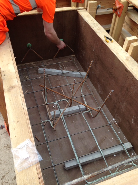
Fig 1. Low absorbing ply moulds, with thermocouple placement and lifting eye detail
2. Storage. The secondary layers were poured whilst the moulds were flat. Once cured, they were lifted to near vertical and sprayed with the regulating layer, at pit bottom in order to replicate closely the conditions in the tunnel. The moulds were struck witin 24hrs of the construction and the panels were then shrink wrapped for protection and to restrict the evaporation of any moisture from the back and sides of the panel. The panels were then lifted and transported to the BRE facility in Watford (a journey of approximately 22 miles) after 1 week. The samples were unwrapped and moved to a storage area. The temperature and humidity were controlled for the remainder of the 28 day period at 40°C and 60% humidity.
3. Test Description. Test samples are each exposed to the same temperture/time exposure, as per the EUREKA fire curve dictated by the specification. The test rig is shown in Fig 2, below and the specified target temperatures and allowable deviations shown on the curve, here EUREKA TempTime Curve
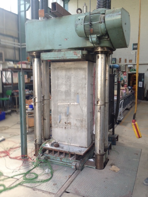
Fig 2. Test rig. Rear of the sample in view
Test Procedure
- Sample transported from controlled storage and weighed prior to test
- Specimen is placed in test rig (500 tonne compression machine) and loaded to an applied axial stress of 5MPa, in order to replicate the hoop stress seen in the tunnel lining.
- The furnace was brought against the face of the specimen and edges are sealed to prevent heat loss.
- Specimen is then heated in accordance with the EUREKA curve using a gas fired furnace. Controlled cooling will take place as part of the curve.
- Following the test, the nature and extent of spalling would be recorded
- Cores to be taken and crushed to test the residual stregth
Acceptance Criteria
The regulating layer would be deemed compliant if it adheres to the following criteria:
(1) The surface regulating layer is to be considered as sacrificial. The depth of spalling of the surface of the main secondary lining shall not exceed 25mm.
(2) The temperature recorded at the level at which the waterproofing layer will be installed should not exceed the temperature at which it may degrade, as advised by the manufacturer of the materials.
(3) Concrete cores- compressive strength of the concrete samples should not be less than 70% of the original design compressive strength at 28 days
(4) The temperature recorded by thermocouples attached to the reinforcement should not exceed 450 °C.
Discussion
In the event no spalling was witness during the test, with the exception of the 3rd test. Here, the spalling was restricted to a localised area towards the bottom half of the test panel. This occured relatively early in the test (18mins). This caused some consternation, but on inspection the spalled area was less than 25mm thick, so in fact the regulating layer had performed its function: as a sacrificial layer. No damage was recorded to the secondary lining.
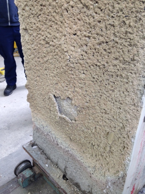
Fig3. Minor spalling in regulating layer only
BASF specification for MasterSeal 345 (waterproof membrane) advises that the product begins to degrade at approx 250degrees C. The highest recorded temperature at the interface between secondary lining and reg layer was 50 degrees and therefore well witin the safe envelope to avoid degradation of the waterproof layer
Cores taken subsequently was mandated to demostrate at least 70% of the 28 days strength of 28 N/mm^2. In fact the lowest recorded stregth was 65 N/mm^2, easily fulfilling the residual strength requirements.
Finally, thermocouples at the extreme end of the rebar, closest to the heat source recorded temperatures not exceeding 120degrees…well within the 450degress advised by the manufacturer.
The test result was a success, and following submission of the Materials Compliance Report, was accepted by Crossrail. In fact, what this demonstrates for me is that in the event of a fire in the tunnel, the structural integrity of the lining will remain intact, thus allowing escape and avoiding catastrophic collapse. However, and perhaps significantly, the test suggests that the cost of remedial action to bring the tunnel back into action would be minimal by comparison. Without degradation to the secondary lining and waterproof membrane, the cost would be in the re-application of the relatively cheap regulating layer, at a thickness of 50mm.
