Site Two Fifty One – Some Engineering Thoughts
Tower cranes. If a tower crane were to fall over and land within 4m of a railway, it must have its foundations checked 3 times (initial design, internal check and external check).
As part of the risk mitigation requirements Network Rail say the crane has to have its working load reduced to 75% of its capacity. Generically this seems sensible – reduce the load to reduce the possibility of the crane falling over.
Due to the location of the railway in relation to the tower crane, it is clear the adjacent buildings prevent the crane from slewing onto the track when loaded. Therefore any variable load would act in a restoring fashion, reducing the possibility of the crane overturning towards the railway.
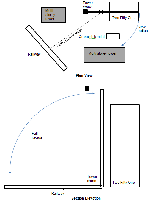
Sketch showing tower crane position in relation to other structures.
Therefore reducing the working load would in fact make the situation worse. The worst load case is therefore an unloaded crane with wind loading. So I’m not so sure a generic application of reduction in loads by 75% makes sense…
Shear Stubs. I beams laid on their side have been used as “shear stubs” to resist shear force applied from the retaining props fixed across the site. The stubs have to have reinforcement bars protruding through them. The holes for the bars were put in the wrong place.
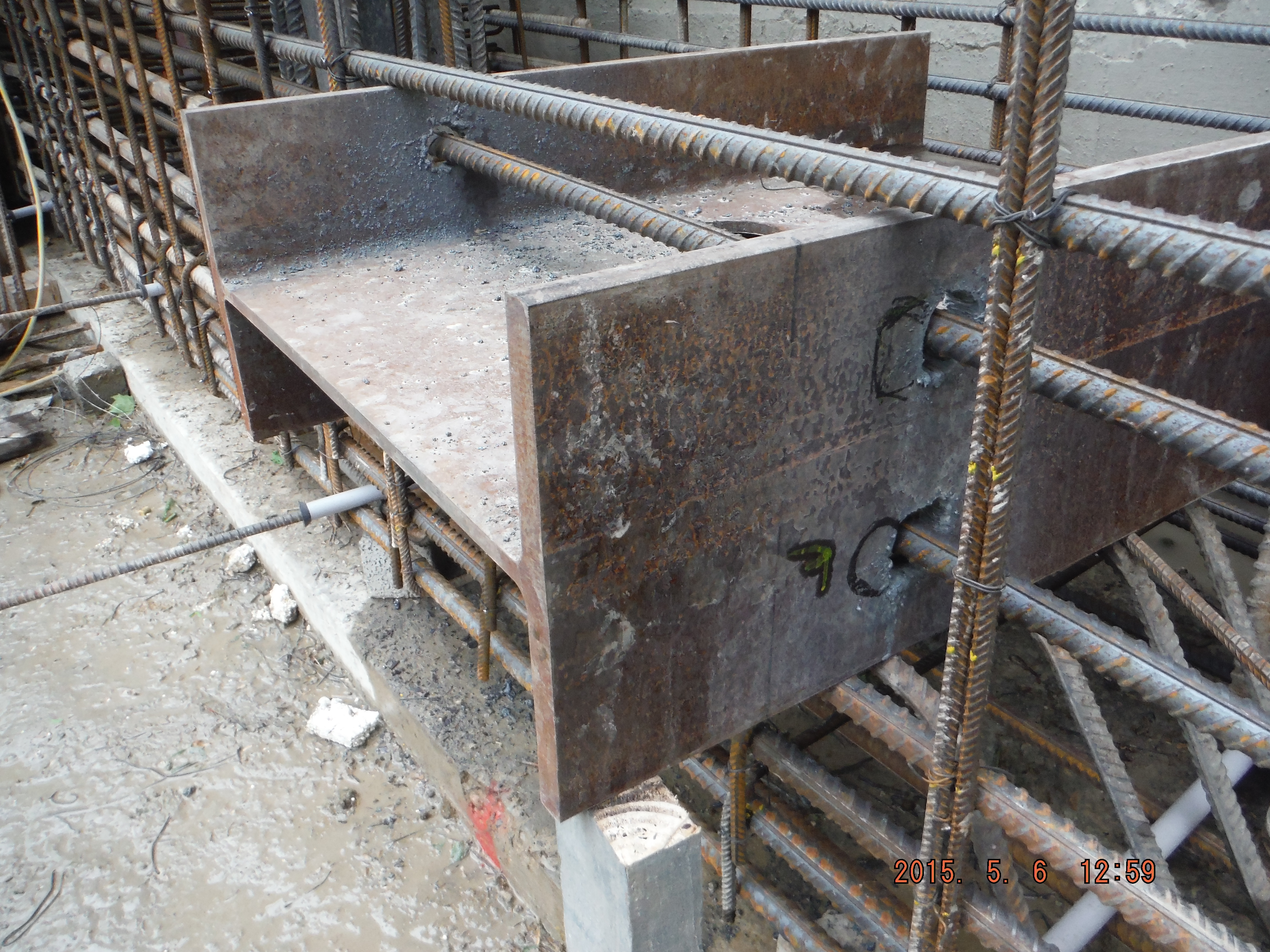
Shear stub, reinforcement holes in the wrong place.
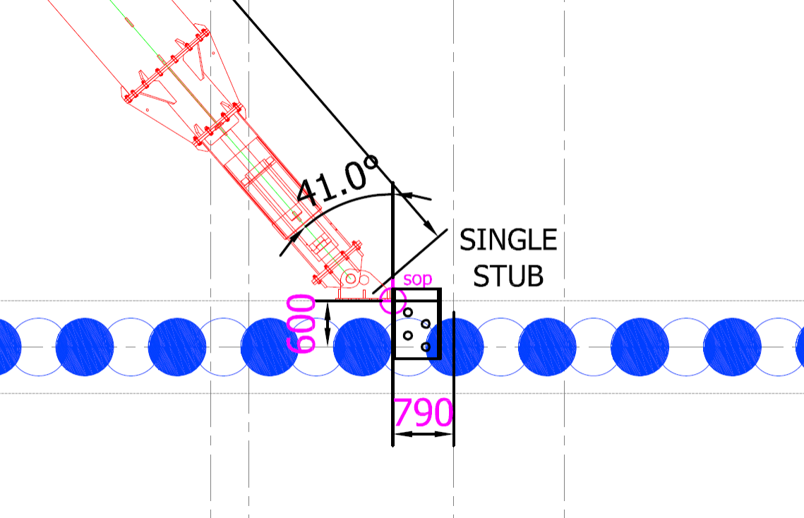
Example of a position of shear stub in relation to prop.
So what? Correcting the problem (increasing the hole size) will result in the flange having a reduced area to be able to resist the force applied.
Action taken? Remove shear stub and have a think.
Thoughts:
- Different stubs have different shear forces applied depending on angle (angle near 90 degrees = less force applied against stub) of the prop (and axial prop load).
- A stub is designed to take a point load of up to 1200kN. The highest prop load is 1140kN giving a 95% utilisation.
- The stub is encased in concrete and therefore it provides resistance against its flange area (625mm x 307mm = 192,000mm squared).
- The area is reduced by 2 x 50mm diameter holes for rebar to pass through (4,000mm squared).
- The incorrect holes reduce the bearing area further by 9000mm squared.
- Based on a total area of 188,000 mm squared the reduction in area is less than the 5% capacity of the worst case situation.
- So the answer – Keep the stub in (too late), reuse stub in any location.
Other thoughts. If the holes were drilled too far towards the near face (i.e. where the prop end plate will act), consideration of the section failure in bending would be important as the section modulus would be reduced, and therefore moment capacity in bending.

Hmm, I think a little numerical modelling around the composite section might just show the exptent of potential spare capacity. Alternatively a qualitative check against the prorietary end plate. What form would any failure take, how much indication would you get and what remedial action could be taken? What’s the risk??
Forgot to say, Tower crane issue – absolutely, engineering meets process and I bet ignorance and fear of thinking will win through by belligerence and bureaucracy. Good post.
We have exactly the same load restrictions, but no buildings to stop the slew. So instead we have had to fit slew restrictors to ensure that without any doubt network rail are bonkers!
On the shear stop
I took a section 450mm deep with a 10mm web and 15mm thk and 150 wide flange and 500mm embedment into the capping beam and placed 1200kN @ 45 degrees and the load applied at 250mm from the capping beam face
This section is OK with FoS’s getting down to a little above unity – so fine for temporary works
Richard, Guz, John, many thanks for the thoughts.
Richard, agree model method to confirm (and John thanks for the reassurance) is a sensible approach. The end plate also has 4 x M20 bolts drilled and resined into the capping beam so further reduction in applied shear force. In all, a bit of an overkill but perhaps useful in protecting against user error as we have demonstrated.