Service diversion.
This week’s blog will revolve around the services along the western boundary of phase one. The services that are currently in position were put in by Carillion last year as per the agreed design. These services include HV cabling that provides power to the temporary transformers on phase one as well as phase 2. That’s 3.75 MVa of power for phase one alone. The key point to takeaway is the HV cabling is live and being used. The other key service is the foul water, which needs to be in situ to allow commissioning to take place.
Unfortunately (for the client) the as built services now appear to run smack bang through where phase 3’s basement (crisscrossing in and out of the sheet pile wall) will be. Phase 3 cannot be re-designed so the services are going to have to move in order for phase 3 to go ahead. This ideally needs to be done by October this year as that’s the start date for phase 3 (main contractor not announced yet) and it needs to be done whilst keeping the power on to phase 2 and 3. To complicate matters phase 3 is being built on top of the Northern Line extension (NLE), the ground works for which have already started.
Carillion were briefed by the client’s consultant Burro Happold (BH_ two weeks ago as to the situation. Three COAs were presented and the preferred (selected by the client and BH) COA identified for CCL to pursue. We will be back briefing this week. The brief we received with respect to the three COAs considered was:
COA 1 single stage plan
The first option for diverting the Western boundary utilities and drainage is a single stage diversion. This entails providing temporary power generation to the ongoing Phase 1 and 2 construction works. This will enable all of the existing utilities requiring diversion to be removed and constructed along their permanent alignment in one single stage of works. Once complete, the diverted utilities and drainage will be energised and temporary generation/alternative supply will cease. This will then result in the phase 3 sheet pile wall being installed as close as 1m away from buried live HV.
COA 2 two stage plan
To avoid the need for alternative supply and generation to the ongoing Phase 1 and 2 construction works and subsequently piling in close proximity to a live service, a two stage diversion plan was considered. Within the two stage plan, power supply is maintained via a temporary HV diversion within the Phase 3 site, avoiding the basement secant piling wall line. Once the temporary duct alignments are installed, a swift switch over is undertaken at convenient connections to the existing HV network, facilitating the required diversion works to all of the utility networks along the western boundary. Upon completion of the diversion works, piling along the western boundary corridor can commence within the Phase 3 basement. Upon completion of piling, power and water supply can be swiftly switched back to the new diverted utility alignments, with the temporary arrangements subsequently de-commissioned.
COA 3 Tunneled Drainage and Phased Utility Diversion plan.
To avoid the need for alternative supply and generation to the ongoing Phase 1 and 2 construction works, a tunnelling option has been explored for the installation of the diverted foul drainage network to remove the majority of the required diversion via open trench installation whilst maintaining live services. Within this option, the launch shaft at an existing location will be utilised to tunnel the diverted foul drainage route north to a new reception shaft. From this reception shaft, the remaining 30m of required drainage diversion can be installed via open trench installation.
Upon completion of the foul drainage diversion, works can commence on the diverted HV supply alignment. The new HV alignment has been designed to avoid the existing live HV supply where possible, however some crossings are still required (notably at the existing entry and exit to the existing switchgear). In addition, the diverted HV alignment is required to cross the existing Phase 1 water supply. The plan would then be to conduct one shutdown and switch over in a very ambitious 48 hour period.
Chosen COA:
The tunneled drainage and phased utility diversion plan has been selected as the preferred COA for the Western boundary utility diversion works. The key risks associated with each COA are summarised in fig 1. BPSDC and BH highlighted the main drivers behind the selection of the preferred COA as being the costs and procurement risks of temporary HV supply as well as the potential to delay the final commissioning of the Phase 1 building (which requires completion of all associated utility networks) at the end of 2015. As the Phase 3 piling works are unlikely to commence until October 2015, it was deemed inappropriate to consider the two stage plan.

Fig 1. Risk matrix
Thoughts / reflection
Every time I re-read the three options that were presented by BH and the client and look at figure 1 I can’t help but think that the client is placing programme and cost implications well above the safety of the work force who will have to carry out this work. If something goes wrong I’m struggling to see how they will be able to prove that they did everything practicable to remove the risks that working close to HV presents; despite the use of tunneling the chosen COA will still involve new services crossing existing HV with hand digging installation method, which the client wants to keep live, 4 times. This is completely avoidable if either of the other two COAs were chosen. This is going to be highlighted at the back brief to the client, but I very much doubt we will get them to change their mind. The only thing that may throw a spanner in the works is that Carillion policy is to not work with live HV. So the choice of COA 3 may yet still result in temporary generation being required.
Questions for the PET community.
I’d be keen to know the civil’s view on piling so close to live HV. E.g. What happens if piles start to fail? The current plan is to place visual guides at the locations the piles will be driven as we place the new HV cable. This is to give the piling contractor an additional degree of certainty that they are not about to hit a HV cable.
I’d also be keen to know if the M&E community thinks I should be getting involved in this. Obviously the services themselves are M&E base, but a lot of the work associated with getting them in is civils. I think there could be an opportunity to get plenty of B1-3 competency experience. Thoughts?
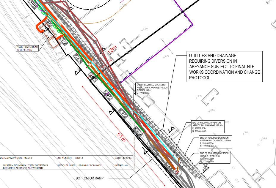
A drawing attempting to highlight how tight everything is going to be. Orange is new HV, brown is is new drainage. Existing services are greyed out.

Hi Rich, nice blog and COA analysis. I suspect managing services of this nature is pretty typical on most projects so all very relevant! I would say the risk piling close to an HV line is about knowing where the HV line actually is. If it was put in according to the plans and there is proof of this (as-built survey) then I would be confident driving sheet piles nearby. Having seen some sheet piling recently they were put in within a 20 mm tolerance. I think that is more of the risk than the likelihood of the piles failing – hopefully that would be mitigated through design checks.
Not sure I would say the same for replacement piles such as continuous flight auger because that has a much greater radius of influence.
If the HV line is going in afterwards, then as long as that is on the retained side of the wall all should be well.
As an aside, the method statements I have seen in relation to excavation near to HV have allowed mechanical digging up to with 0.5m.
Regarding relevance to you – I think it is absolutely great if the mechanical and electrical engineer understands these considerations rather than only being interested from the point of entry into the building. However, I believe the works involved in achieving that is more of a civils task, however I’m sure others will comment!
Damian,
Thanks for the comments. .5m for hand digging rings true with what I’ve heard and read before, although it seems that Carillion apply an additional level of safety on top of this. Good news on the 20 mm tolerance for the sheet piling – that is what is can be seen just above the services on the drawing.We’ll also potentially need to sheet pile to create a cofferdam to get the microboring underway. Just below the services on the darwing are a series of rectangular boxes which are the foundations for a vehicle ramp and will be formed by augered piles. This is where they are talking about putting the markers (plastic tubes) to ensure the piles go in exactly the right place and don’t hit the HV, but they’re still close, although it will only be a visual aid and won’t physically guide the auger. What kind of zone of influence would we be taking about and what exactly could the influence be? Or is that too broad a question without knowing the ground characteristics?
Hi Rich – If the augering is cased (i.e. a big hollow tube is buried then the contents within are augered out) then I would say minimal influence. If the auger is not cased (CFA type) then it depends on the ground. I expect you are in either river terrace deposits or London Clay. Clearly ground water plays a large part, but effectively if granular (sand/gravel river terrace deposits) the radius will be much larger (see an earlier blog of mine where undermining occurred up to about 3m) than clay (more likely to be minimal, but then see Olly’s blog where he had a pile collapse). Perhaps getting a bit too into the weeds (and guessing on what your ground might be like really is uncertain!). Hopefully the piling contractor will be fully briefed on the situation before undertaking the works…
Damian,
Cheers. I’d like to think it’s going into the weeds a bit too much, but my current experience is that nobody considers the second order effects or anything outside their lane. I’m in no way confident that whoever is de-conflicting the new service route and the phase 3 foundations will have considered what influence the piles could have on the cables and there’s potential that there’ll be more trouble further down the road. Perhaps I shouldn’t care, the phase 3 work will be carried out by another contractor and it’s the client’s money to do with as they want.
Either way Rich it sounds like a second blog/couple of AER paragraphs potentially waiting to be written if it does all go wrong!
Rich,
What are they planning on tunnelling with-microboring again? Here’s some major issues that they have forgotten about!!
-Obstructions. There are also a number of old cast iron gas pipes in that area too, we had them all tapped and broke them out. They are all marked on a drawing that I left behind and gave to BPSDC, let me know if you need a copy as I think I have it electronically too.
-Groundwater. It was taking us 2 hrs every morning to pump out the trench boxes to complete the drainage in that part of the site.
-Fenceline. Also the NR fence wasn’t shown in the right place on a number of drawings so that is closer than it looks.
-Comms. The comms cannot be within a certain distance of the HV (1m I think?). We had major issues with that trying to fit everything around the water and FW MH near the transformers.
It sounds like T&T and BPSDC have forgotten the problems we had with that area last year! Are Mike Varney and Jonathon Kirwan still involved?
Have a read of my old blog here, these are the sorts of pipes down that way!
https://htstrial.wordpress.com/2014/02/21/get-off-my-land-you-cant-park-here-and-whats-this-big-pipe/