Site Two Fifty One – A few examples of how things can be done.
Site Two Fifty One – A few examples of how things can be done.
This is just a quick blog with an update of where things are on site. If there is an area of interest I will expand/find out answers in the comments.
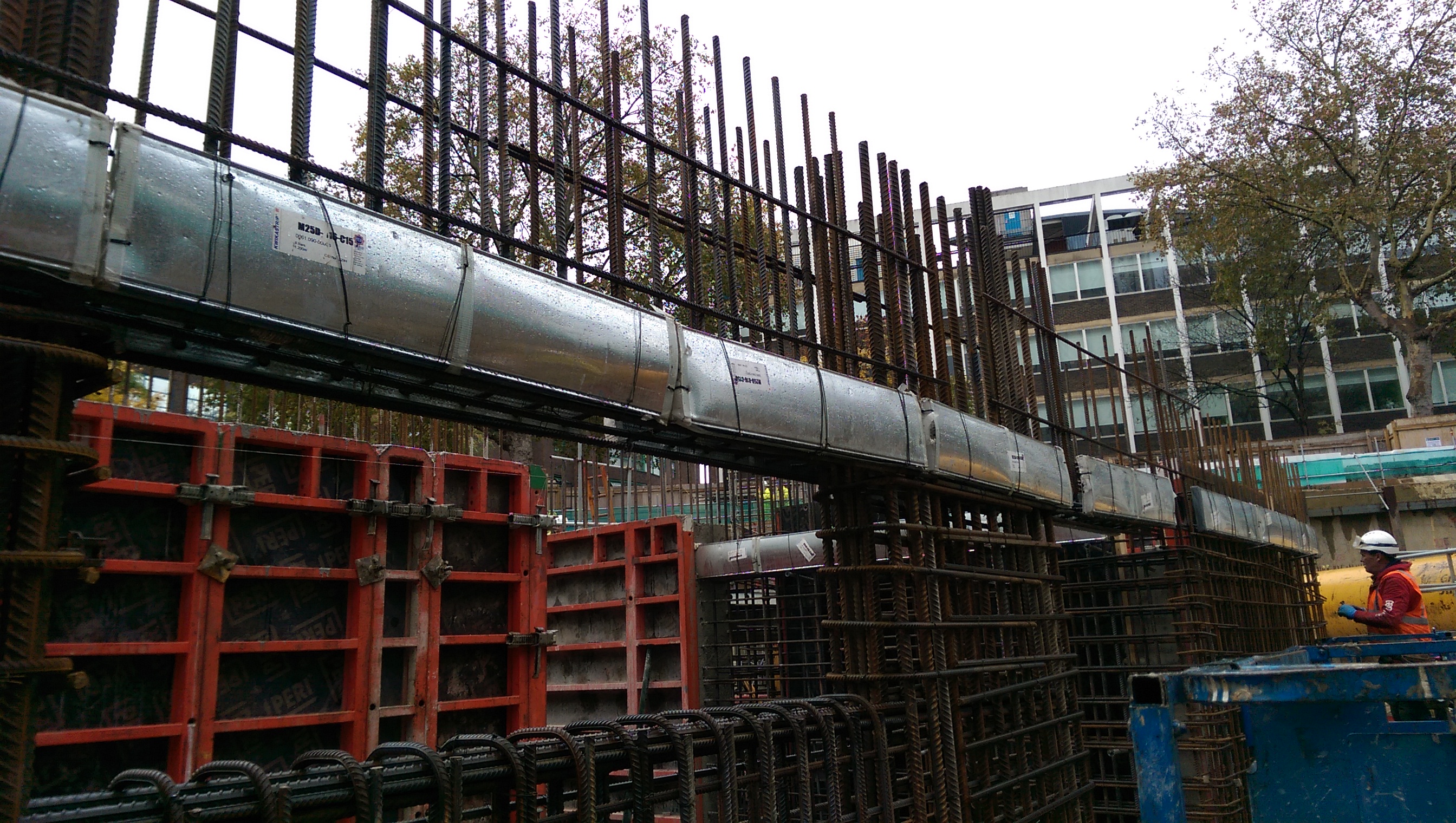
1. Kwika strip slab starters. As previously mentioned we would be using kwika strip in the walls. This shows how they look pre-pour. The bars have about 30 mm cover within the case.
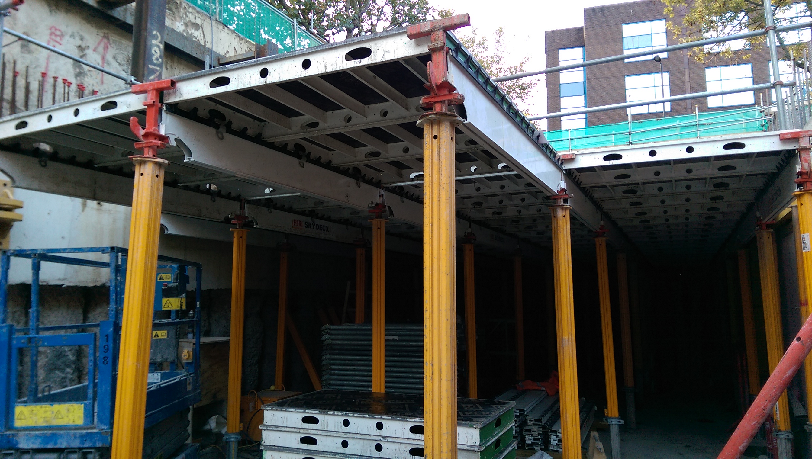
2. Sky deck falsework. This is a Peri system which is quick to erect. It requires bracing using chains and a section of trusses to transfer 2.5% of the vertical load. We did not silicone between joints but used a plastic t-section. There was some grout loss down the faces of the walls and columns which was washed off to avoid disfigurement.
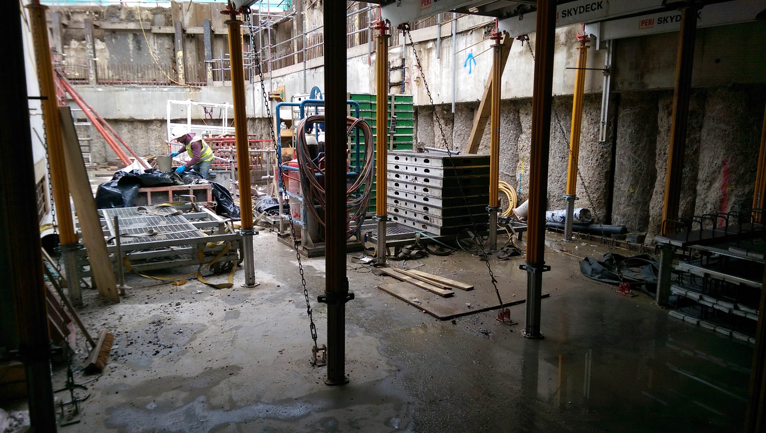
Chains providing lateral restraint of the Skydeck.
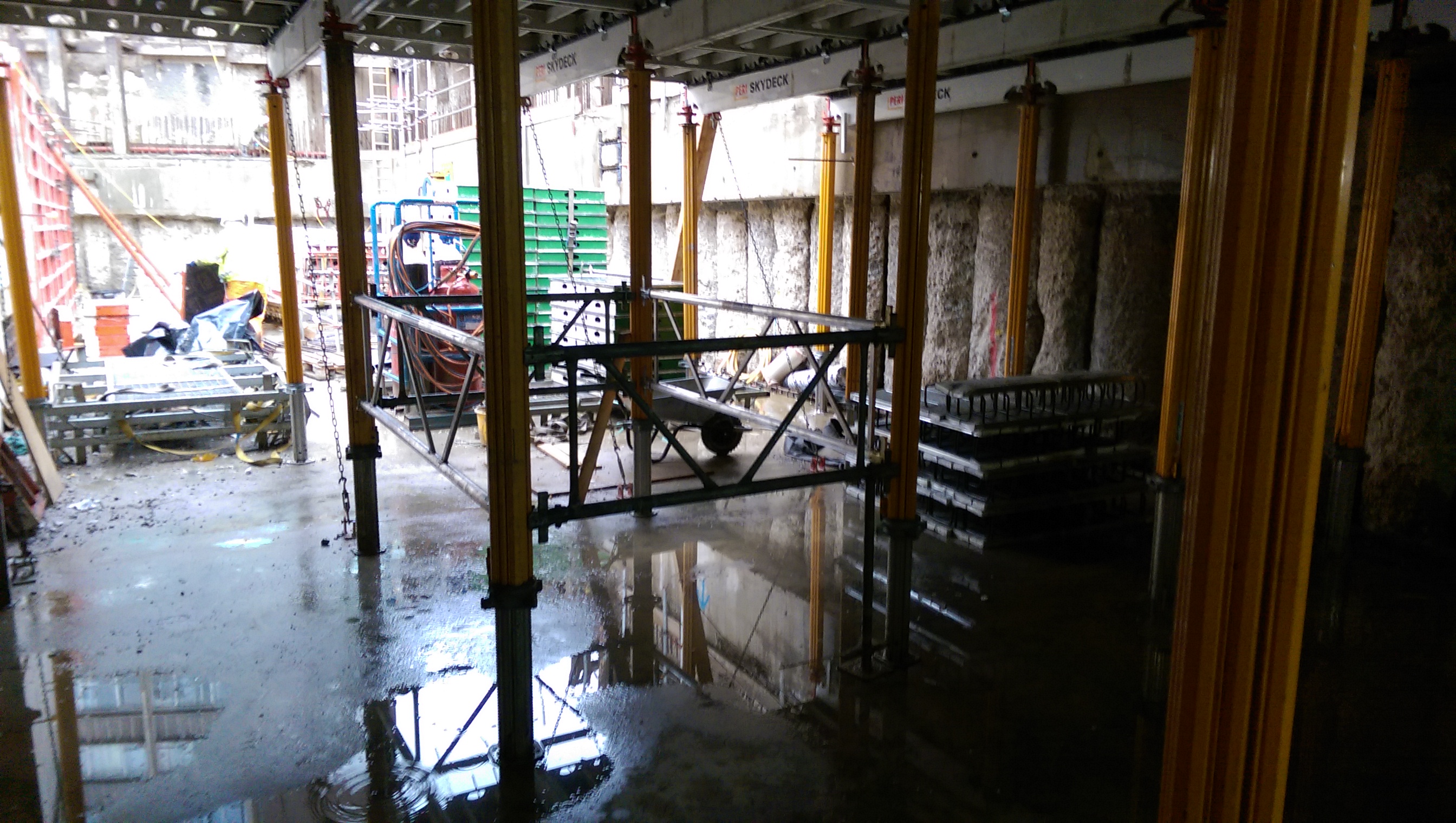
Braced panel to transfer vertical load to the ground.
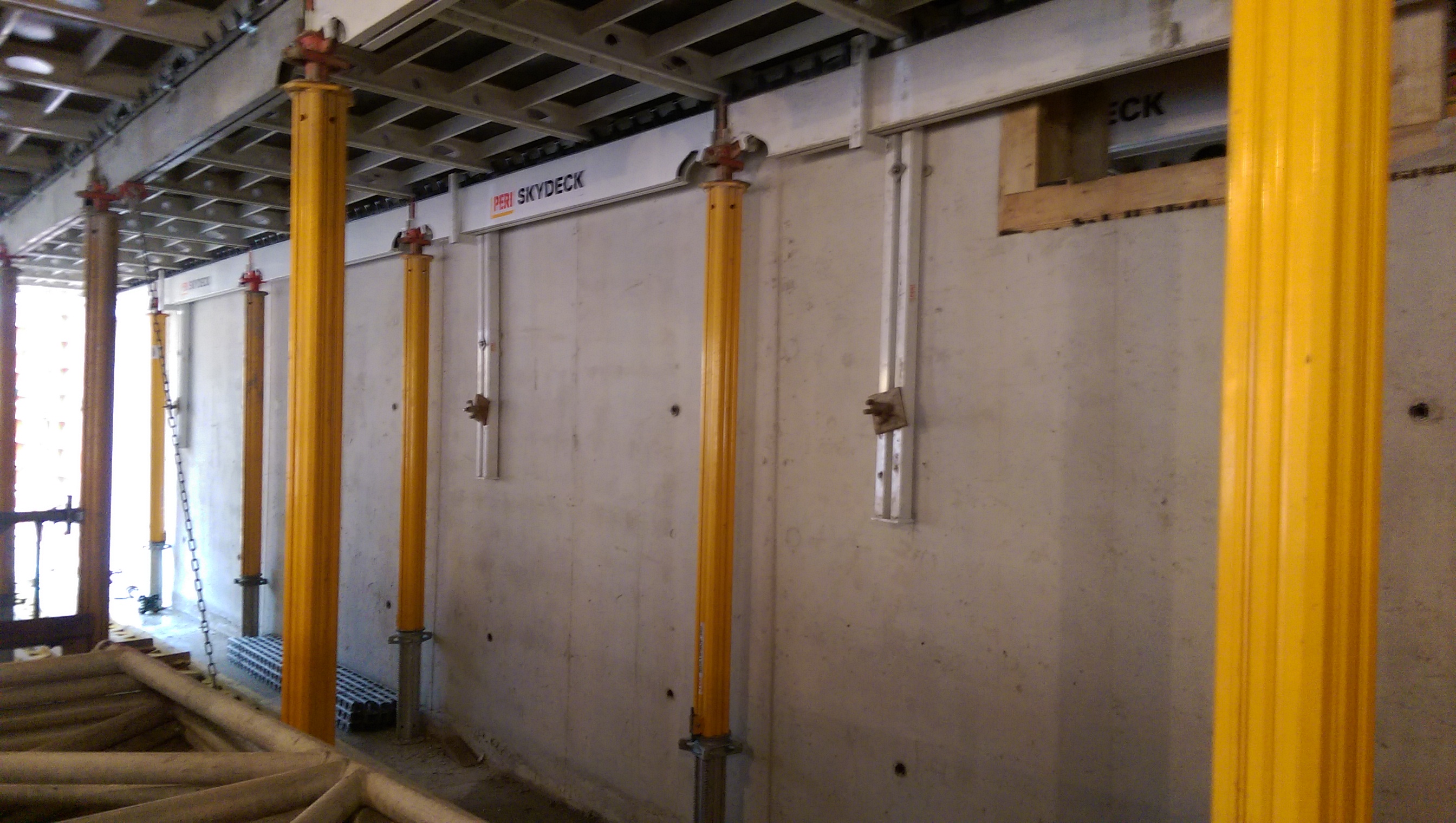
Wall brackets to provide lateral restraint.
3. When can I strike? The next challenge was to know when the falsework could be struck. The method used is based on a crack width assumption that compares construction loads with unfactored service loads against the concrete strength (fcu) (see page 186 in ‘CS30 Formwork. A guide to good practice, third edition, 2012’ for full details). This slab is for a plant area so the ratio is low resulting in the concrete strength required to be 15N/mm2 to strike which should be achieved in 4-days. However, we will crush cubes daily and have thermocouples placed in the pour and cubes, so we will correlate to give an accurate actual concrete strength, which if reached earlier than 4-days will mean we strike the falsework sooner.
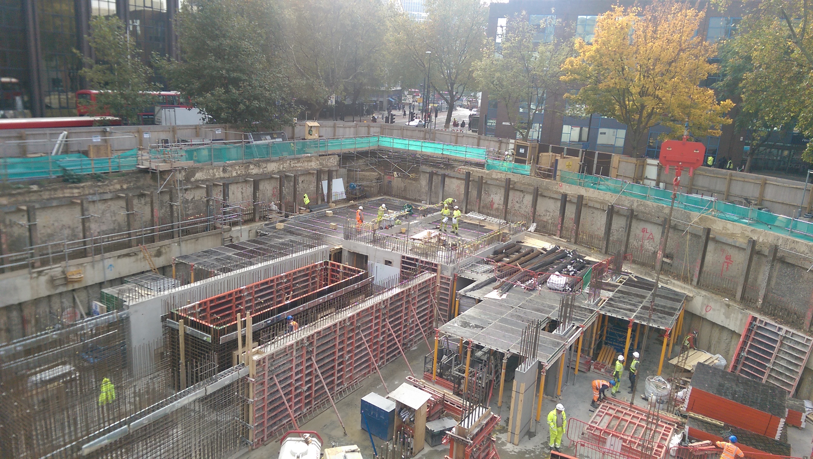
Skydeck falsework being installed at B1 level.
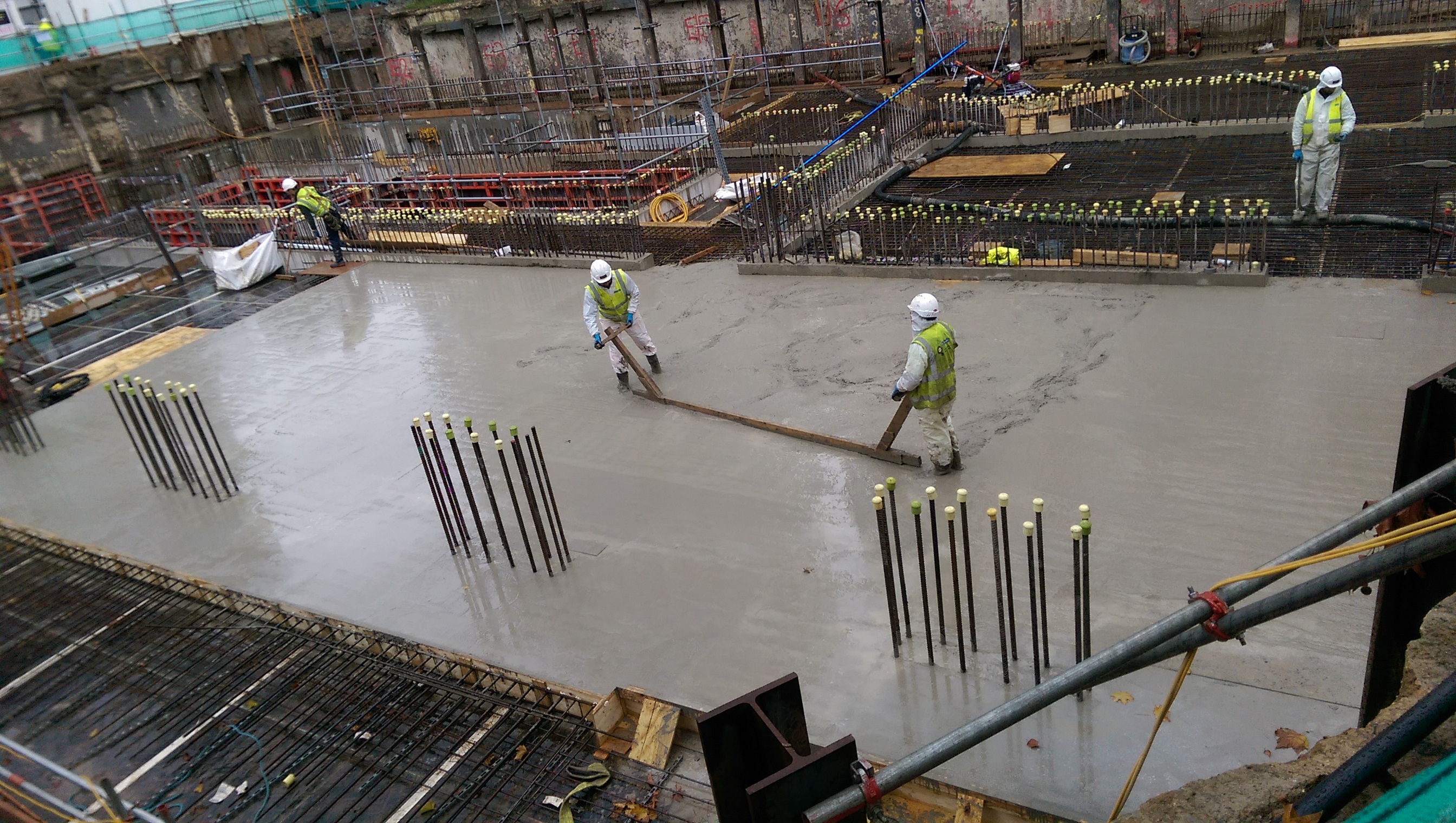
Slab pour – puddling complete around columns.
4. Concrete miss-match. Some of the building’s columns are 60N/mm2 whereas the B1 slab is only 40N/mm2. Therefore within the B1 slab pour a section of 50N/mm2 concrete was puddled around the column locations to avoid a miss-match in strength of more than 10N/mm2…
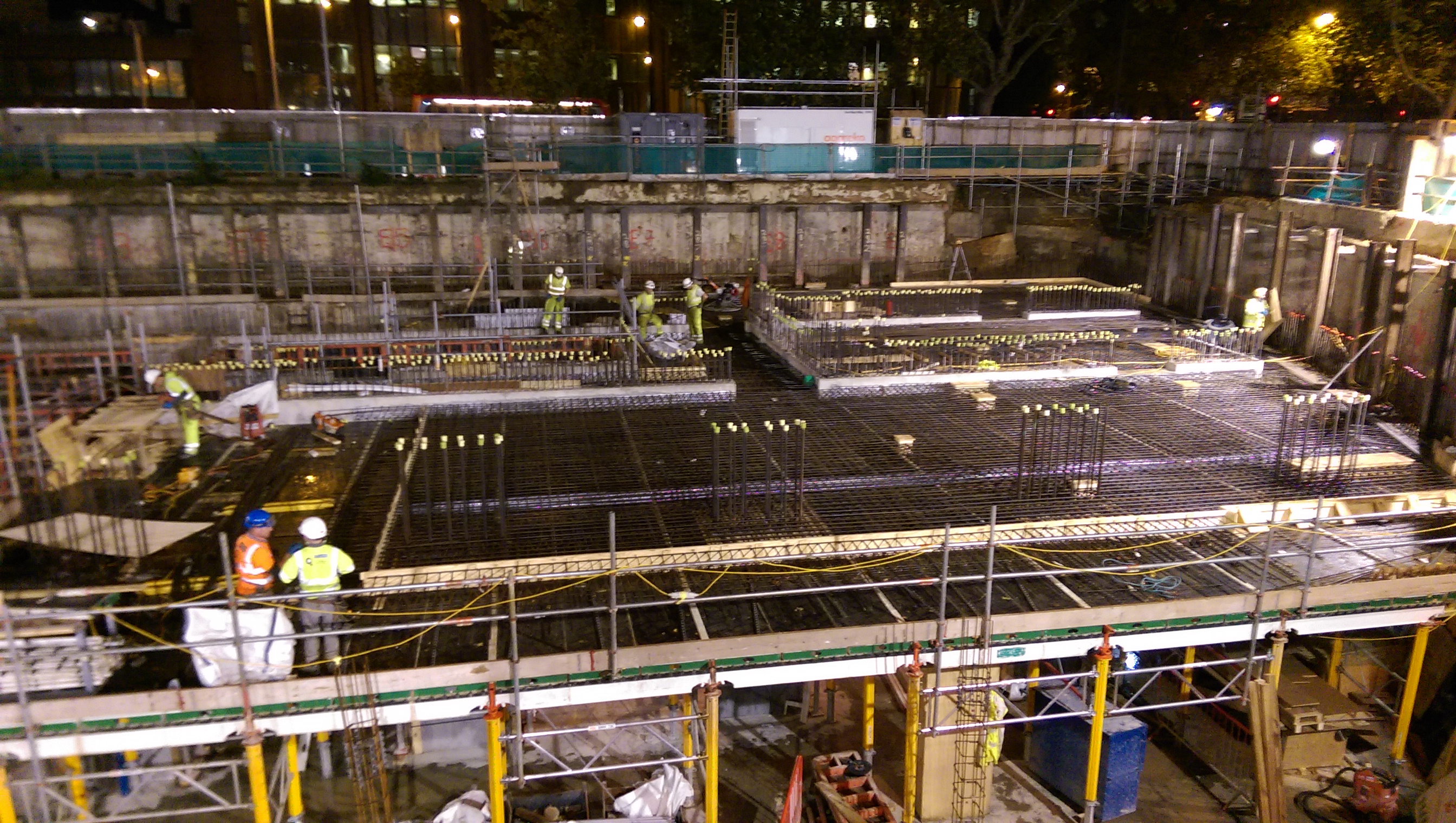
Hi-rib stopend at near-side of slab pour, near column starter bars.
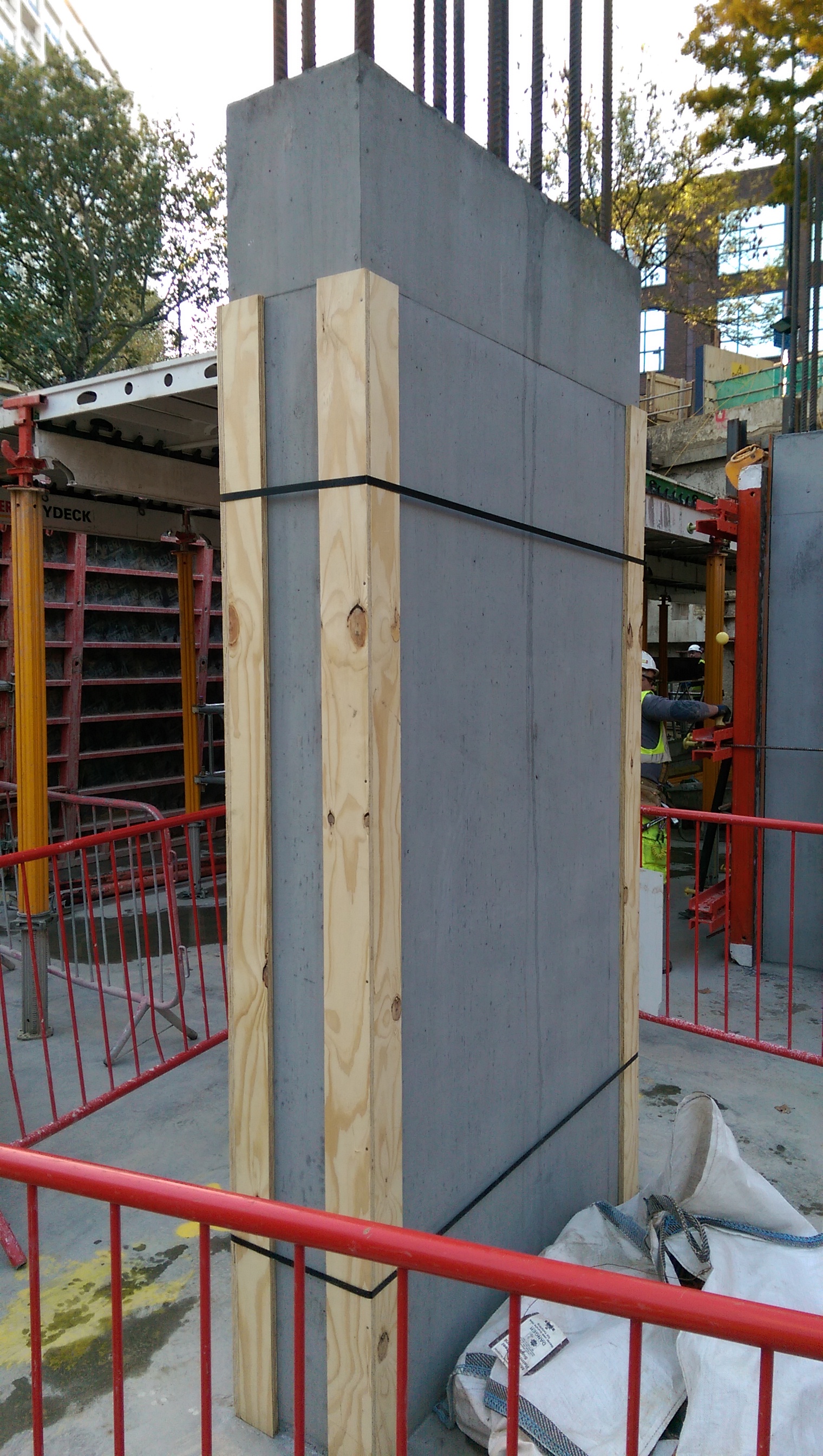
5. Column formwork. 2-sided formwork – props used to keep column vertical rather than taking significant horizontal load. The horizontal load is carried within the internal ties.

6. How do you build this? This is a sump 3.1m deep by 600mm . 600mm. To install any sort of formwork and then strike it would be too small a pit to put an operative in to work. Not necessarily the best solution but a quick one is to use precast sections (similar to manhole rings) to build up and pour the walls around it. The outer size of the chamber had to be increased but there was no spatial constraint to prevent this so hopefully the plan will work!


Thanks Damian,
Are the U bars on the reverse of the kwikastrip laced into the cage behined or just lapped and tied?
Also… Just looking over this again and you show a braced panel with the commment that it transfers vertical loads?! Surely this actually does three things: Helps stability during erecting, resists lateral loads and effectively shortens the struts – reduces their effective length but doesn’t actually transfer anything verticallly. No?
Richard, Thanks for the comments. Kwika strip is tied into horizontal bars, not just lapped and tied.
Not sure which planet I am on at the moment, yes of course horizontal loads. My three photos of the chains, braced panel and wall ties were all supposed to demonstrate transfer of 2.5% of the applied vertical load as horizontal force to the ground.
Damo,
Why is the sump pit so deep? Surely it only has to hold a small sump pump? Is there other drainage entering it lower down?
Henry, deep because vehicle lift pit (reason for drainage questionable – how much water is really going to come in…) needs to drain into something and the slab level is much higher. Arguably the sump is less than a metre deep, just that metre needs to be 2m below slab level!
Damo, makes sense. How large is the chamber now, even if it was 900mm square I’m not sure I’d be happy being sent down to clean it or service the, hopefully removeable, pump.
Henry – no need to put anyone it the chamber – puddle pump can be lowered into the camber and used to empty chamber with needing to put someone in it. As for servicing it – good question but all it should see if some minimal rain water. There is a grate over the gulley which should stop any objects entering the drainage run.
Damian
The final throws of site? Good practical designs easy to build!!!!
All the best Neil