CRAC & Pipe
I recently handed back my Leadership in Energy and Environmental Design (LEED) responsibilities, which I’ve been covering for the last several months whilst the actual LEED Accredited Person (LEED AP) was on maternity leave. The timing coincided with the resolution of an issue which was high on the principal contractor’s ‘concerns’ list. It involved a Computer Room A/C (CRAC) unit and is another example of some poor contractual documentation which has led to confusion on this job. The issue has been exacerbated by the fact that the project is constrained quite heavily on what LEED points it can pursue, making those which it can particularly valuable. The issue started with an RFI submitted through the usual channels. It was labeled as ‘hot’ because it was holding up the delivery to site of the CRAC units.
As you can see from the contractor’s calculations below the Life Cycle Global Warming Potential (LCGWP) appears to be in excess of the LEED stipulated value of 100.
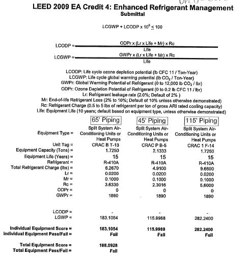
Contractors Evaluation of LCGWP
After a little digging I found out that this calculation was incorrect because it was based on the three units in confinement, when the actual calculation is meant to take the whole system into account. Although these parts of the system appear to be way out of the environmental requirements the system as a whole still passes. This fact made up a part of my eventual RFI response.
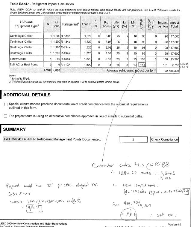
My calculation of LCGWP of whole system
The second part to this, and most importantly is the root cause of the problem. This was in the way that the requirements were communicated; there is conflicting information on the equipment schedule. As you can see below, the table calls for a DRCU-312 unit, but note 4 calls for the DRC-334 model.
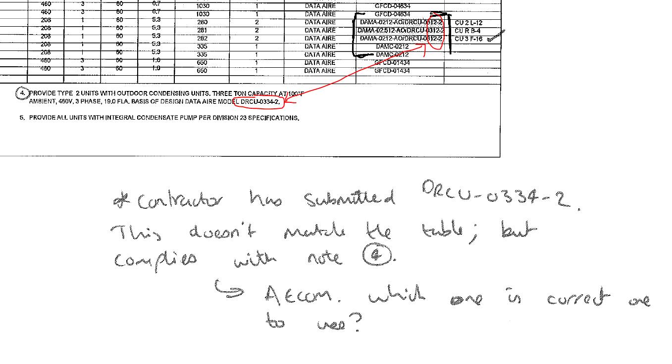
Conflicting information in contract documentation
Although it has been shown that the impact is minimal and the system as a whole still passes the issue has still caused delay in delivering the CRAC units to site. This has in turn delayed the overall system installation. Fortunately this work does not fall on the project program critical path and so impacts are minimized.
This is one example of many which has highlighted issues with the contract documentation. I imagine the designer will have done some design quality control (buildability, inter-discipline co-ordination etc) but they do seem to have missed quite a lot. I expected, on a large project, that there would be some discrepancies and bits of missing information but I have been surprised at how regular an occurrence it is here. Are any of you having similar issues or is it just this designer being slack?
For me, key take aways are with respect to quality control. This is not just a site practice, but starts at the very outset of a project. It is important to control the quality of the contract documentation also, and ensure that the drawings, schedule, specifications etc are all ‘synchronized.’ The impacts of not doing so can affect all three elements of the time/cost/quality triangle. As future PQEs I expect that a large element of this will fall to us to do.
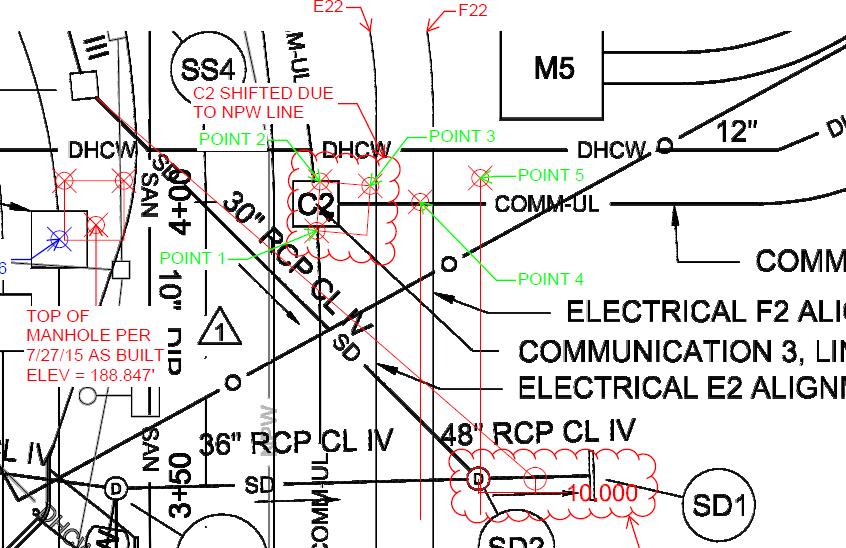
A completely separate issue, but which loosely stems from the same root is a conflict between adjacent projects. Here a drainage run from one project is required to be installed in shared space. The conflict arises due to an electrical ductbank, which is hardened, and has been installed slightly out of alignment, and at a higher elevation than design due to various other site constraints. This means that it now sits pretty much exactly where the adjacent project’s drainage run is supposed to go.
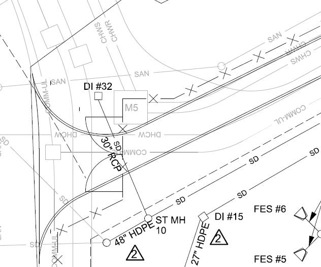
Original Design – Drainage run in question is DI32 – SD10 running under the road.
As built showing shift in ductbank centreline
Solutions I was able to proffer were move the drainage run run to the East of the ‘M5’ structure or change the inlet type. Both solutions would require re-design / confirmation by the designer because of the potential changes to the drainage areas, and requirements for confirming flow and velocities in the amended drainage runs. The first option was ruled out fairly quickly when I looked at the elevations of some of the other utilities in the area and realized that the pipe would have cut straight through some other utilities which had already been installed. Option two was therefore looked at more closely. The designed inlet was an overflow type, quite common here and usually seen in bio-retention ponds.
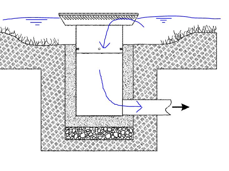
Typical inlet sketch
This inlet type meant that water would pond until it reached the inlet level, then enter the drainage by falling into the inlet chamber and on into the pipe where it is carried under the road (see original design above) and into the drainage system. It was the drop into the inlet chamber which was part of the problem here. By changing the inlet to a culvert instead the same function is achieved, minus the initial drop in elevation. Negating this drop meant that the drainage run could now pass over the ductbank, which it was previously conflicting with. See sketch below using, made using information from the as-builts and design drawings.
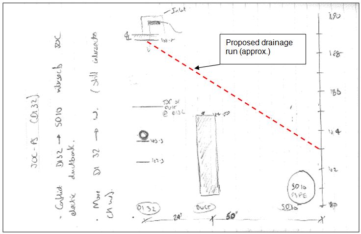
Sketches from notebook
I proposed to the designer that the inlet design was changed and calculated that a gradient of around 5.5% would maintain the original designed invert of the pipe at the SD10 (see picture above) This meant that the manhole structure which had already been delivered to site wouldn’t need to be changed. Any more than 8% would conflict again with the ductbank. Steep then!
The design came back from the designer yesterday:
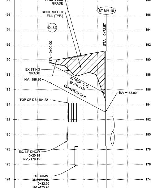
Approved design
Its hardly ground-breaking stuff, but it does throw up some pertinent issues. Firstly the obvious deconfliction of adjacent projects. This has been a near constant issue, and one which has caused some contractual variations. Clearly the best way is to do it early. In this instance it can be seen that information about the location of utilities were made clear to the adjacent project, however in squeezing in a drainage run between so many utilities the adjacent project has been burned by, I guess ‘unforeseen ground conditions.’ (ie the ductbank wasn’t where they were expecting it to be). Second the fact that the client on my project has the requirement to harden utilities. I gather that it is far from standard practice, but concrete wrapping ductbanks in areas of high utility/ services congestion adds to the complexity of installation. Predominantly this is because of the space required, but also it takes much longer and costs a lot more. I’ve been able to make a large saving (I blogged about it earlier) by questioning the requirement to harden some of the less critical utilities here. There is also the question of maintenance? In any case, in this instance the client would not have given latitude to remove the requirement for hardening, and so the conflict will always have arisen. There is however a minimum level of cover to be observed on ductbanks when they are close to the surface. Perhaps if this was applied to those at a deeper level, as a sort of ‘fudge factor / buffer zone’ then the designer might have been constrained at an earlier time in the project and might have arrived at the culvert solution in the first instance.

Its interesting that even the best performing chillers only dip below the required level of 100. Is there a chance of getting a copy of those docs Brad or are they secret?
Brad , good stuff this
Interesting to see that you say wrong specification is was the root cause. My reading would be that the design was based on a different type of condensing unit (that’s what the unit code suggests) but another condenser was installed. As the E&Ms will be painfully aware there’s no problem with this approach as long as the unit performance data can be adjusted to reflect conditions outside of those rated.
The risk in LCODP and LCGWP calculations is more closely related to two factors – refrigerant choice and refrigerant charge. Use non ODS (ozone depleting substances) and LCODP drops to zero, no problem there. The condenser is just a heat exchanger, is follows well trodden principles, the key is to charge the system with the minimum refrigerant that has a low GWP hence targets are set
Incidentally do you knw which GWP horizon value is used in LEED (10yr, 30 yr or 100yr)?
Any chance I could have some more information on this? Sounds useful to use in the classroom.
Certainly – I will speak with Henry and see what useful information I can send across to you (to save just sending loads of useless niff naff).Typically the life cycle value for the equipment is 10 years and the Integration Time Horizon (ITH) is 100 years.
Mark, When I get some stuff from Brad I’ll give you a call and see what is most useful to you, I may be able to find some other live examples from buildings.
Without seeing the full schedule I can’t be sure but the note at the bottom only describes what was used for the basis of design. We aren’t allowed to detail exactly which unit they should use and the contractor can install what they please as long as they meet the performance specs of load and the LEED requirement. I can see why they struggled to work out the LEED score piece but regarding the schedule I think they may have taken one look at it and given up as there was a perceived difference there. I am currently fighting a subtle RFI war on my contract where the main contractor is nit picking the design in order to save rework where they just installed equipment before it was approved.
Brad, I’m intrigued by the change from overflow inlet to culvert without some thought about silt trapping and potential use of wier walls. Surely the overflow inlet had a purpose ohther than to add expense to the draininage layout and therfore this has either been sacrificed along with any Leed points for water treatment or there is more to this than you tell.
Brad,
A lot of my issues are associated with design or as people have previously mentioned a lack of communication. We have a dedicated design manager within Carillion’s MEP team. As the job title suggests his role is not to design, but to manage the design process. This isn’t happening which impacts on site delivery. Two examples off the top my head are that we currently don’t know exactly how our potable water supply gets into the building and the pipework for out display fountains are clashing horribly with the residential water supply.
Rich,
The one thing to always remeber is that water under pressure, rather like electricity, gas and communications, can go uphill as well as down without issue. Drainige only flows one way under gravity and when it runs out of space you’re into expensive, space demanding, power hungry, maintenance ridden pumping!
Rich,
Which is why SRW’s boosted residential supply will almost certainly be moved to accomodate the gravity fed return pipework for the display fountains.
Richard, The inlet is purely there to convey surface runoff from a small area north of the road into the overall storm system. It was never intended as any form of water treatment and so LEED has not been impacted. I mentioned that this this type of inlet is fairly common, so I think its probably a case of ‘that’s what we always do.’ In this instance I think the issue was more due to the de-confliction of utilities between two different projects, combined with the fact that one project couldn’t put them where they were designed to go. The designed drainage inlet was always going to be close to the ductbank as designed, there was very little fudge factor. I’m not sure if there is a best practice for this but it seems sensible, especially where gravity fed utilities are concerned.
Rich – out of interest are you on a design build project? (USACE recommends that position to contractors on DB projects as good practice) Is the design manager you mention supposed to co-ordinate all other disciplines or is he just responsible for MEP, with a supervisor to look after inter-discipline co-ordination?
Thanks Brad,
Happy with the concept. There are at least two other solutions to this that I know of from past experience. If you raised this at review I would have asked the same question and, given your response would now want to know a) Why is silt protection important and what silt protection you might want to consider for the SW system now you have a stright culvert inlet. Is it needed? If not, why not, and if so, how might it be provided. and b) what has been the change in cost and time for installation through using a culvert as opposed to an overflow chamber inlet? Has it changed the associated installation an maintenance risks?
Richard,
The silt protection here is important for a number of factors. One – it is demanded by the Maryland Department of the Environment who has strict standards it enforces to ensure that contaminated water doesn’t reach the Chesapeake bay. This is to protect the bay against further damage which it has sustained as a result of decades of industry in the area. Two – Silt protection maintains the integrity of the drainage runs and flows. Admittedly I’m not too au fait with this area (probably will become more so in the design attachment) however by inspection I would say that given the steep gradient the first run at least is probably self cleansing! The first manhole has a sort of sump area where water can collect and sediment will settle before rising to a level where it will enter the rest of the drainage run. This will require periodic maintenance (not sure how often) Site conditions at present (its not stabilised / lots of sediment in the surface flow) mean that there is inlet protection at all inlets. This reduces the amount that can enter the drainage run in the first place and comprises of a build up of aggregate around the inlet, and a sort of fabric cover over the inlet, both of which catch fines. When the site is up to the final grades, the soil is stabilised (planted / seeded etc) roads placed there will be much less silt entering the inlets and so the temporary environmental measures will be removed. The area at the entrance of the culvert will be grass and so inlet protection is probably not required once it is in the designed condition.
Changes in time and cost in this instance are fairly minimal and extend to the procurement of a new inlet section. As I mentioned the new design is such that the existing manhole can be used (its already been placed) and the drainage run is already on site. With regards to installation risks this re-design mitigates the chance of clashes. The density of utilities at deeper elevations that passing over them is the least risky.
Thanks for the comment -hopefully that covers everything.