Oz PCH – EMC Gland Wars: The Subcontractor Strikes Back
Introduction
This is a follow-up blog from the previous Electromagnetic Compatibility Concerns. It discusses the on-going issue of RF emissions leakage from VSDs and their associated mains power cable. Please feel free to re-read my previous blog for the background to this issue.
Outgoing Mains from VSD
After being issued with a Non-Compliance Report (NCR), Fredon have addressed part of the issue. They have now fitted an EMC gland to one of the many VSDs which we, the commissioning team and NDY (design consultancy) reviewed. Figure 1 shows the new gland (red circle) but there was still an issue, hence the review before reworking all incorrect VSDs.
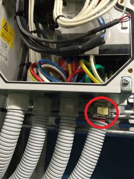
Figure 1. New EMC Gland Fitted to VSD.
They had left the pig-tail (covered in green heat shrink) and connected it to the earth terminal as seen in Figure 2 (red arrow). Why is this an issue?
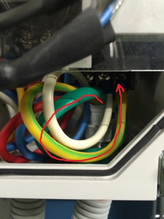
Figure 2. Pig-Tail still Present and Connected to Earth Terminal.
The fact they now have the correct EMC gland in place, which ensures a 360 º connection to the metal base plate and is connected to the rear metal back plate of the VSD (which is connected to earth) makes the pig-tail superfluous. It also potentially acts as a source of RF emission which is what we are trying to reduce. Therefore, it should be cut off when the new gland is fitted; this has now been instructed for all installation of EMC glands to VSDs.
VSD to Motor Via Isolator Switch
A further, and much bigger issue is the power cable that from the VSD to the motor via an isolation switch. Here Electro Master (subcontractor to Fredon), are still saying what they have installed is correct. Figure 3 shows the switch with plastic glands top and bottom.
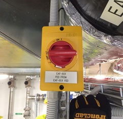
Figure 3. Isolator Switch between VSD and Motor.
When asked why they hadn’t swapped them out for proper metal EMC glands they referred us back to the their original response to the NCR stating that – what they have installed is in fact better than what the specification requested, where by relying on a compression fitting to achieve galvanic connection is a point of failure.
What Electro Master has failed to understand is the principle behind what the cable screening is actually providing. Figures 4 & 5 shows the wiring arrangement within the isolator switch.
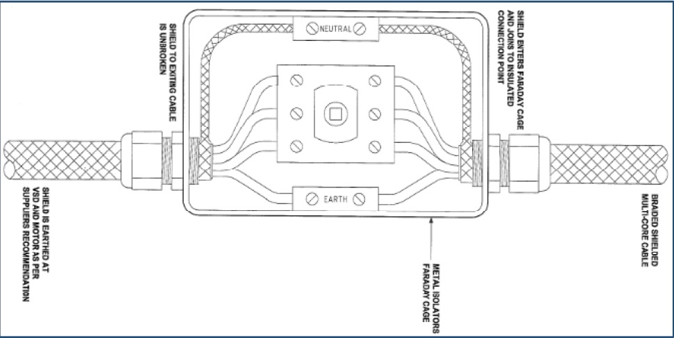
Figure 4 & 5. Electro Master’s Wiring Arrangement as per the Isolator Switch Installation.
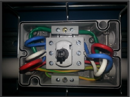
Figure 4 & 5. Electro Master’s Wiring Arrangement as per the Isolator Switch Installation.
The metal switch housing acts like a mini Faraday Cage and Electro Master were adamant that as long as the screening was continuous through the switch, by connection via the neutral terminal, then any RF emissions will be kept inside the Faraday Cage. However, this is not true due to the plastic glands used. Effectively, as soon as the screen is pig-tailed and the 3-phase and earth cables exposed, the RF emissions they produce are free to emit through the air inside the Faraday Cage which will then leak out through the plastic glands.
The solution is to install the screen being in contact with the metal housing via metal EMC glands either side of the switch and with the pig-tail cut out. This then completes the screening and the Faraday Cage will work as per the theory.
This is substantiated by the following two papers found at the links beneath:
Variable Speed Drives and Motors – GAMBICA / REMA Technical Guide.
Best EMC Installation Practice for VSDs – Technical Manager – Power Electronics.
According to the GAMBICA Technical Guide – “Where local to motor isolation is required for safety purposes, it is essential that the switch enclosure should be conductive, and form part of the “Faraday Cage” surrounding the entire PDS. This means that the cable screens should be correctly bonded/glanded to the enclosure”. As shown in figure 6.
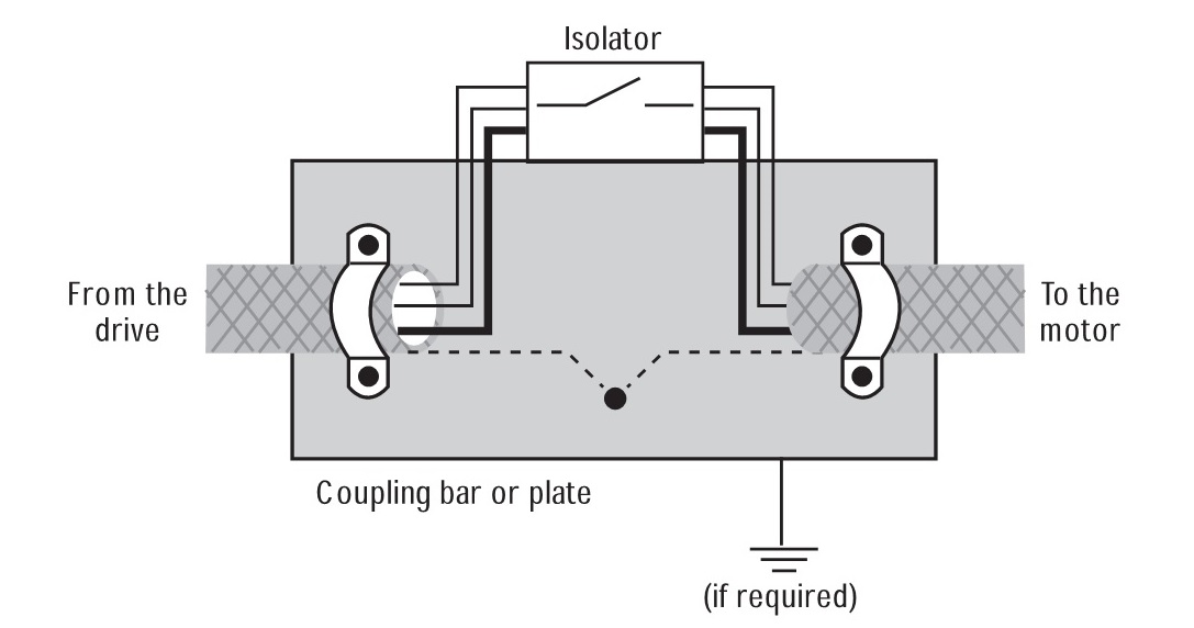
Figure 6. Arrangement for Interruption to Screened Motor Cable.
Additionally, Best EMC Installation Practice for VSDs states that shown in figure 7.
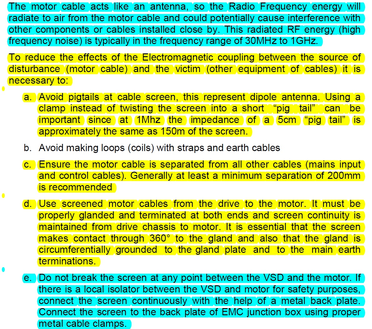
Figure 7. Extract Referring to How to Reduce the Effects if EMC.
Contradiction
However, after further research the following document was found which, to some degree, contradicts the other papers above.
Schneider Technical Note – VSDs: EMC Screen & Output Isolators.
Schneider’s Technical note states that “Common practice is to use an EMC gland to connect the shield into a metal enclosure to continue the Faraday cage, but safety requirements often mean that the enclosure must be bonded to ground at that point as well and hence compromises the EMC HF return path”. As shown in figure 8.
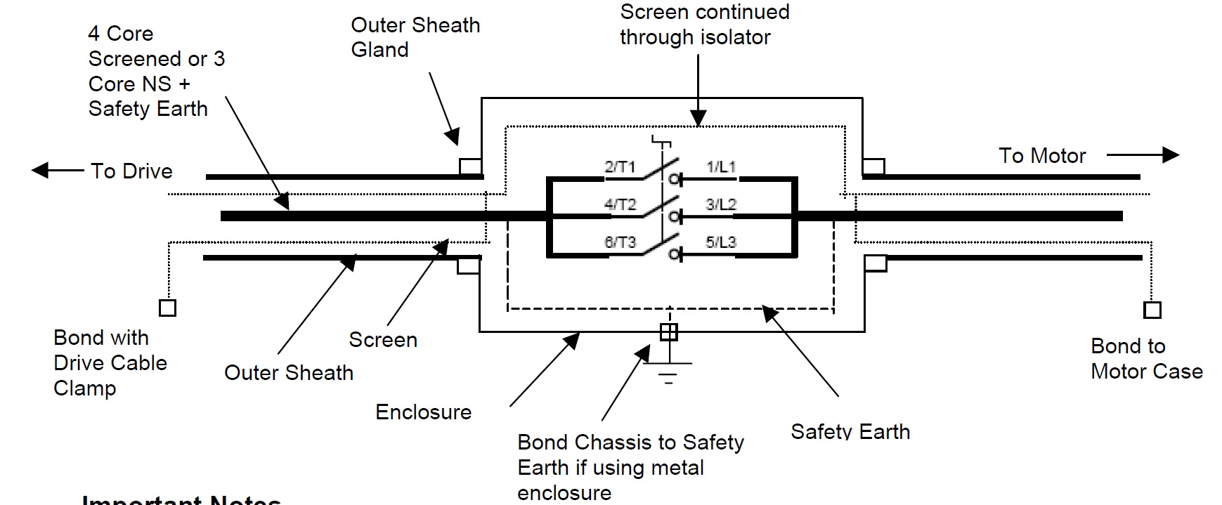
Figure 8. A Practical Work Around for Maintaining Safe Bonding and an Uninterrupted High Frequency EMC Return Path.
Important Notes:
- Continue the screen braid through the isolator ideally using the same braid and keeping this as flat as possible. Avoid pig tailing and/ or twisting the screen.
- The screen is not connected to the chassis or earth at any point other than at the motor and drive.
- Ideally EMC type glands should be used to bond the screen to the motor chassis
- Use the drives EMC shield Clamp to bond as shown.
This is exactly what Electro Master has installed but they have still used pig-tails which is bad practice.
Conclusion
Through reading the papers above, limiting the RF emissions seems imperative in ensuring there is a low impedance path to enable the current to return to its source. My conclusion is that the high frequency low impedance path between the VSD and motor must be maintained (by the screen) even if there are local motor isolators installed in-between. In this particular case because the VSD and motor are both grounded to earth (at each end) then avoiding a third earth connection is imperative otherwise you end up effectively splitting the cable which breaks the single faraday cage theory; the reason why Electro Master are adamant that they should not connect the screen to the metal isolation box which is earthed.
Therefore, it is my opinion that what Electro Master has installed, based on the earthing arrangements used, has met the intent of the specification. The ‘litmus test’ is the implication associated to leaked RF emissions that could cause interference with specialist medical equipment which could then potentially result in a child’s death.
Although patient safety must always be the priority, you could also consider other factors that would be a consequence from making Electro Master strip-out and install EMC glands, such as: increased cost (to Electro Master – up to $40,000) and potential time delays to commissioning.
What is very apparent is this area of electrical engineering is highly specialised and above my experience level as well as anyone else’s in the office. So although I conclude that Electro Master’s installation of the isolation switch being sound, we have and must refer the issue to NDY for them and their specialist electrical engineers to provide us with an answer for the way forward.

I am sure you are after my job when I retire!
Cheers John, anytime soon?
Fran,
Are they going to have to resolve the pig tail within the isolation switch as this doesn’t seems to go against some of the best practice you’ve highligthed. Also how have JH got to the stage of installing 400 drives before realising this issue. Was there not an ITP for this installation and some form of benchmark for the first installation?
The detail with the isolation switch will be resolved based on what NDY come back with. Pig-tails are to be avoided wherever possible, although trying to join the the screen in the isolation switch would be pretty difficult without doing so. There was mention in one of the reports about bringing the strands together but not a pig-tail per se; not sure how the two really differ to be honest.
As for ITPs and how have we got in this mess…well it was spotted about three months ago but the contractor was saying that most VSDs would have filters fitted and they were waiting on them being delivered before the finished install. Turns out that there were a good number of drives without filters and even those required EMC glands. The particular subcontractor, Fredon, have been a nightmare on this project. Not to say it is all their fault, I believe JHG have a QC issue in that a lot of things fall through the net. Also, not helped by NDY’s slow pace in reviewing installations and commenting on the quality inline with their specification.
Fran, you make an interesting point about JHG having a QC issue. On our site as I mentioned on a previous blog we have one subcontractor working for us and a number of other subcontractors doing all the electrical work on site. JHG have one electrical engineer/supervisor covering all this work. In a pre start this week the PM asked him how a certain element was going and he answered that he had no understanding of what they were doing so couldn’t comment on their progress…. Granted we are only dealing with tomatoes so it may not be as critical as a hospital, but I would have expected a bit more JHG quality assurance representation. Commercially if something is found to be wrong at a later date JHG could be opening themselves up for a world of pain.
Matt,
I hear you…in my experience on this project it seems like quality issues and indeed the install even meeting the design specification are only identified when we, the commissioning team, come to look at it. I think maybe it’s as a result of everyone panicking that construction is still on-going (now almost 5 months late from original programme PC) and getting stuff installed seems hard enough, let alone installed correctly.
We’ve now had three of our four construction managers leave the project; possibly indicative of it nearing completion and them wanting to secure a job elsewhere before they are pushed but with not good when they leave with all their project knowledge and when all hands on deck are required.
On the commissioning team picking up all the issues I have noticed that my project has stalled as the contractor scrabbles around to collect together all of the paperwork they had previously ignored in the spirit of ‘keeping the job progressing’. I assume they think that we’ll forget the issues that we have raised, and logged, if they just keep ignoring them. So I wonder if this is an extension of that same principle.
On the RF issue is there any testing that can be conducted to prove the amount of RF transmission? Have they failed the standard at all?
Henry,
Thankfully in the age of BIM we are able to create issues and assign to subcontractors for their resolution. This is tracked and can only be closed out by the person who created it. Therefore, there is a very clear record. In addition now that an NCR has been raised against the issue they must under their contract comply. Which is why the remaining issue of installation of isolation switches now being referred to NDY for their specialist review/approval. Not withstanding the fact that they also wrote the design specification and are the only party who can approve/non-approve as long as the installation also meets the AS codes – which also requires clarification.
As for physical testing, that is of course an option and may well be NDY’s way of covering themselves and allow them to provide a way forward – all the while remembering time is not standing still.