Archive
Thermal Integrity Profiling
In a recent email conversation with John Moran, he asked me how we at the NLE were quality assuring the large diameter bored piles (2.4m diameter). Good question I said, see my next blog. Actually it applies to both the diaphragm walls as well as the rotary bored piles.
The walls of the Battersea Station boxes are constructed with diaphragm walls. For those who don’t know (because I didn’t really until I got here) how they are constructed here’s a brief explanation.
Diaphragm Wall Construction
The piling rig looks similar to a rotary rig except that it has a massive set of jaws, instead of a rotary auger. I believe a diaphragm wall works like a secant pile wall though I am open to being told that I am wrong on this one.


The rig can cut a panel 1.2m deep, 2.6m wide (or wider) and almost as deep as you want. Each panel is dug under a bentonite slurry to support the excavation during the dig. A deep dig can take up to 7 days to excavate. Once excavated a reinforcement cage is dropped in and it is then concreted using a tremmie pipe.


In TIP, a fibre optic cable is tied to the side of the cage. The technology uses a laser to shine a light through the fibre. Temperature is recorded by measuring the scatter backlight down the fibre at 1cm intervals. The system is accurate to 0.5°C.
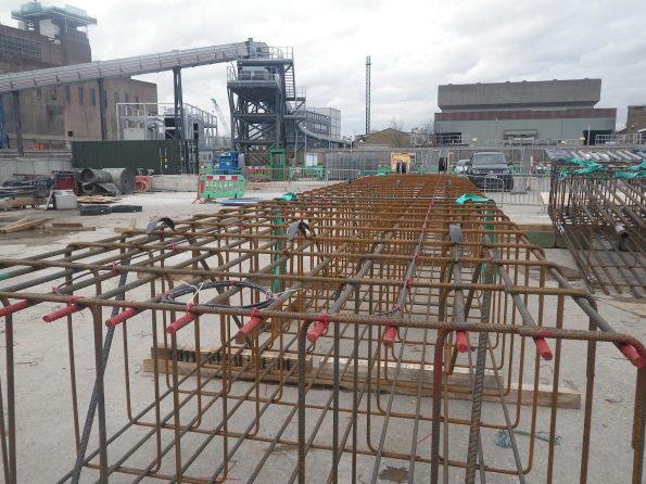
The Bottom Cage showing the Fibre Optic Cable already laid out and two reels ready to extend to next cage.
The instrumentation starts logging as soon as it goes in the ground and records for 48 hours after that. The output looks like the temperature diagram below.
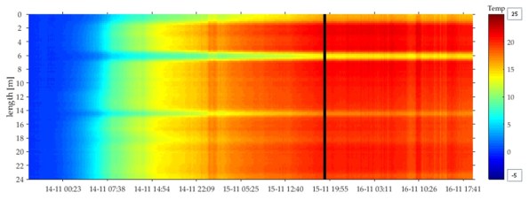
Thermal Profile Over Time
The cold spots around 6 and 14m depth correspond to the boxed out sections where we have rows of couplers that will eventually connect to our floor slabs. The box out in effect shields the concrete from the surrounding soil changing the thermal profile. This also allow us to confirm that the couplers are at the right height.
For comparison, the first three panels were tested with sonic testing and TIP as a comparison. Since it was accepted as a valid method of assurance only TIP testing has been carried out on each panel. As the graphs below on the right show, sonic testing can only verify between the tubes and not outside.
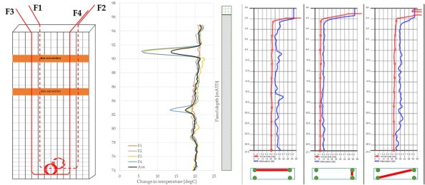
TIP vs Sonic Testing (L-R Lay out of fibre optic cables, TIP testing, Sonic Testing)
In short, this seems like it will be the future of assuring the construction in deep large piles. The advantages of easier installation, testing coverage area and time of recording make it worth the initial cost of the system.
I know that Expanded (Laing O’Rourke piling specialist) use thermo-couplers but I believe that they only record every 30cm and can be quite temperamental.
CFS-N205-2360000-CIV-RPT-00028_Iss1
Temporary v Permanent…
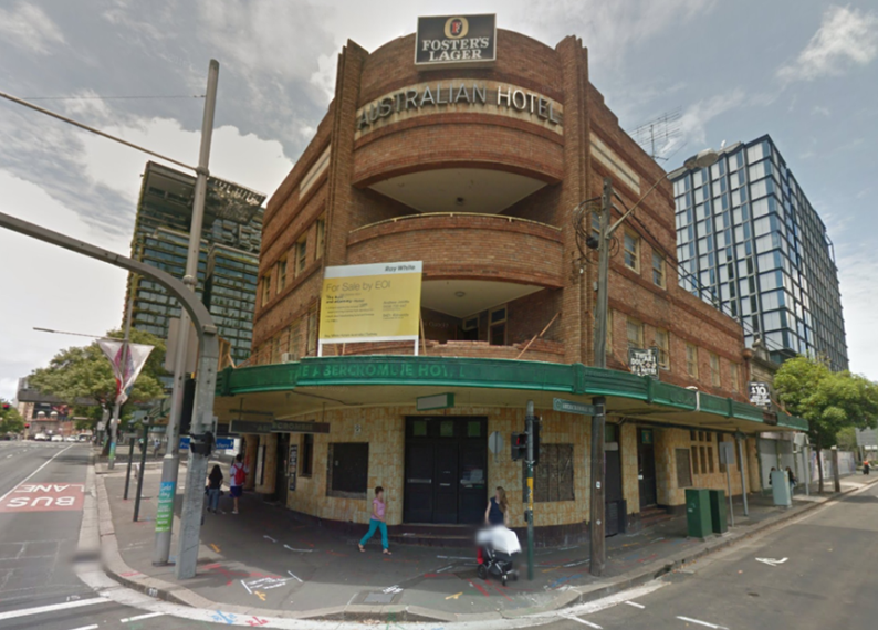
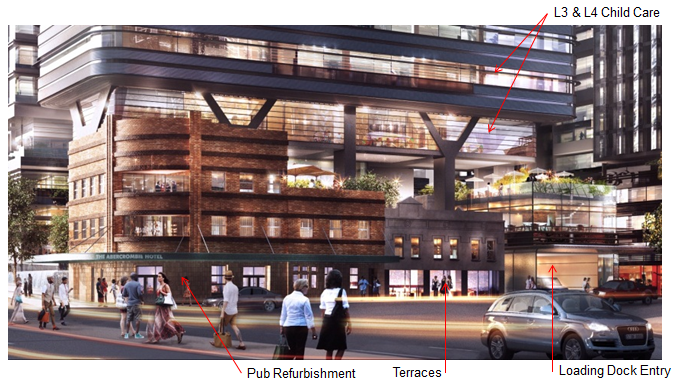
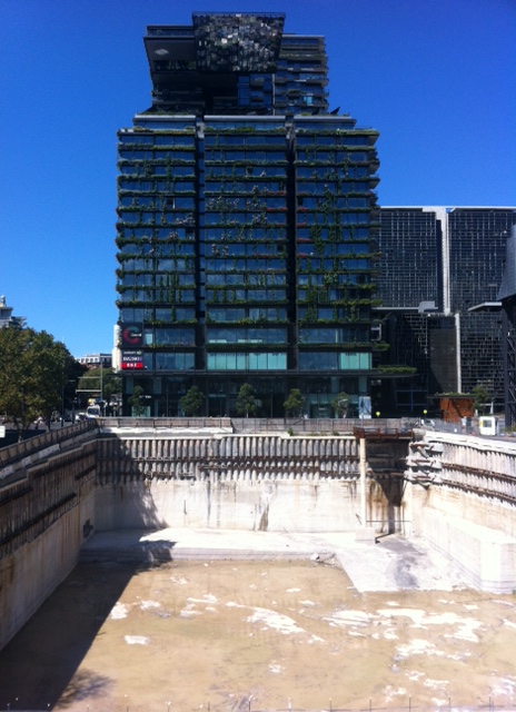
Situation… So I am responsible for the section of the structure which will envelop the heritage building in the image above. In the permanent state, the structure will surround the heritage site as shown in the two images below…
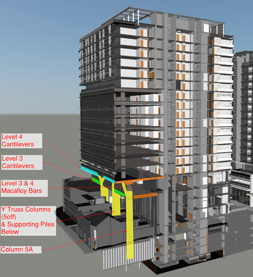
Issue… Whilst the beam, which allows level 3 of the structure to cantilever over the heritage building, clears the roof in the permanent state, it fouls it in the temporary. The beam has to be poured in two stages due to its depth. In order to achieve the required strength between pours, the depth has to increase from that required in the permanent state. This causes the beam to foul the roof of the heritage building… Ah!
Options…
- Accept the collateral damage and remove a section of the parapet wall to allow for the beam.
- Prop the beam in the temporary state, allowing the beam depth to be reduced to that required in the permanent condition, thus avoiding a clash with the roof. However, to accommodate these props the floor boards and roof tiles will need to be removed and ceilings penetrated. The props will have to be strategically positioned to avoid joists and rafters. Once the beam has reached its required strength, the props can be removed, floor boards and tiles replaced and ceilings patched.
The heritage authority aren’t exactly happy with either of these options but think option 1 is the lesser of the evils. A structural survey of the heritage building is soon to take place and if I were a betting man, I anticipate huge aspects of the heritage building will be condemned. If the floors, ceilings and roof need replacing, option 2 may take the lead.
I will keep you abreast of the situation once a decision is made.
Battersea Power Station – Phase3
Like all my Phase 2 contemporaries I have now commenced my site attachment in my case, working for Bouygues UK, on Battersea Power Station Phase 3. I am a site manager with responsibility for a temporary bridge structure that provides critical access to the site.
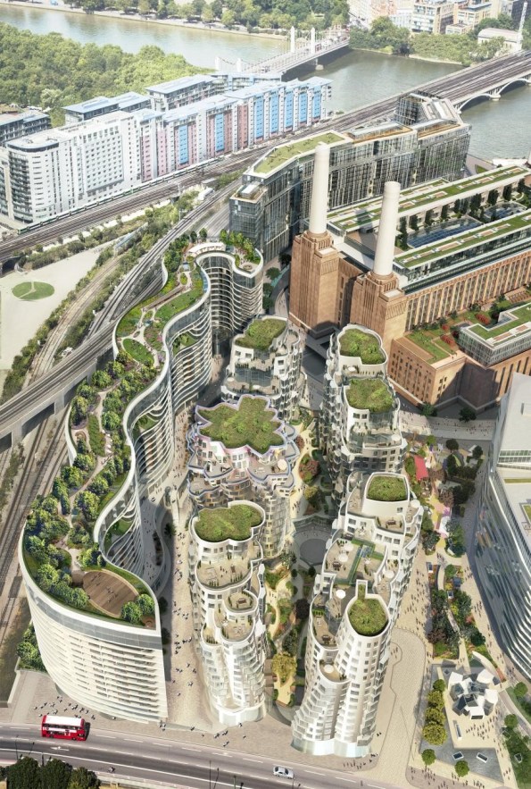
Battersea Power Station (BPS) is part of a wider development of the south bank of the Thames in the Nine Elms area, from Lambeth to Chelsea Bridge, and includes the Northern Line Extension (NLE). BPS encompasses seven phases in total. Phase 1 and 2 are firmly in the construction stage. Phase 1, to the west of the old power station, is predominantly a residential project. Carillion is the principal contractor and the project is now in the fitting out phase with residential occupation in Q4 of 2016. Phase 2 (Skanska) is the refurbishment of the old power station. Bouygues UK were appointed the preferred bidder for Phase 3 late in 2015.
BPS Phase 3 consists of six buildings and includes over 1,305 residential units, a hotel, a health clinic and over 40,000 m2 of commercial space. The client commissioned Fosters and Partners and Gehry’s for the buildings’ architectural designs. All six buildings are over 20 storeys in height and have three basement levels.
The permanent works are relatively straight forward. Clearly, I am grossly oversimplifying the engineering in order to introduce three points that I believe will have future relevance.
Interfaces
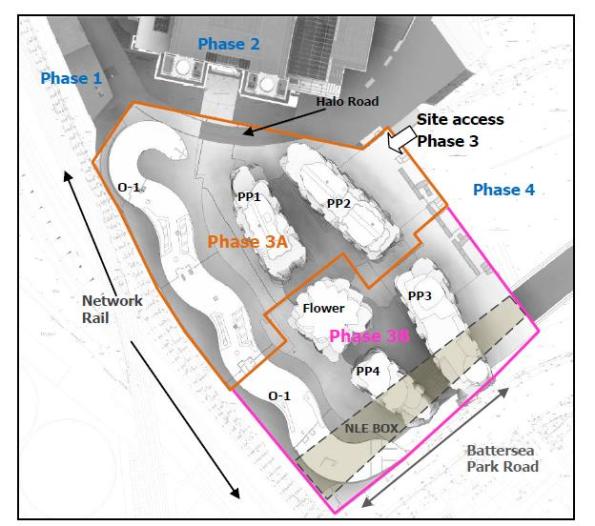
Phase 3 is surrounded and hemmed in by other stakeholders as shown below. The actual project is split into two phases due to the NLE station box in the southern half of the site. This creates some interesting engineering solutions to the problems across the interface. On the western building there will be a construction joint in the middle of the building (O-1) and across the southern boundary there will be the requirement for temporary ground anchors as the basement levels are excavated. There are further interface difficulties with Phase 1 and Phase 2 to the north as a result of their builds being at different stages and Network Rail to our east.
Temporary Works
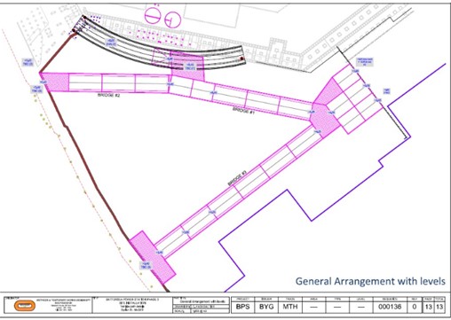
Access (for site deliveries and future residents) must be maintained to Phase 1 and Phase 2 for the entirety of the construction of phase 3 – In effect a highway (same road width as Ex Rhubarb Creek) through our site as we build … The temporary works solution is 3 large temporary bridges with accompanying platforms built approximately at existing ground level which will allow excavation and construction of the basement levels below.
Commercial
Finally and fortuitously for me as my commercial experience is limited the contractual aspects of this job are a bit of a muddle at the moment. Bouygues UK do not have a contract, Bouygues UK do not even have a letter of intent. Our sub-contractors (who were not chosen by us but procured directly by the client) do not have contracts, they do not even have letters of intent… And yet we are all beavering away. Set these contractual woes in the context of the London property bubble and a funding mechanism that relies upon pre-sales and I think I have the beginning of a TMR.
Moving to Site
Over the course of the last week it has been clear that 75% of the “Engineers” on this project are fixed by the processes around gaining permissions and submitting notices in order to comply with the Development Consent Order and Works Information. Consequently a lot of the detail for our move to site has gone unexamined, good for me in terms of the experience I’ll get, but potentially bad for the project because they actually seemed to have believed the rubbish I put in my CV.
My team assembles on Monday to start the early works and the figure below shows some of the frictions that we will have to deal with.
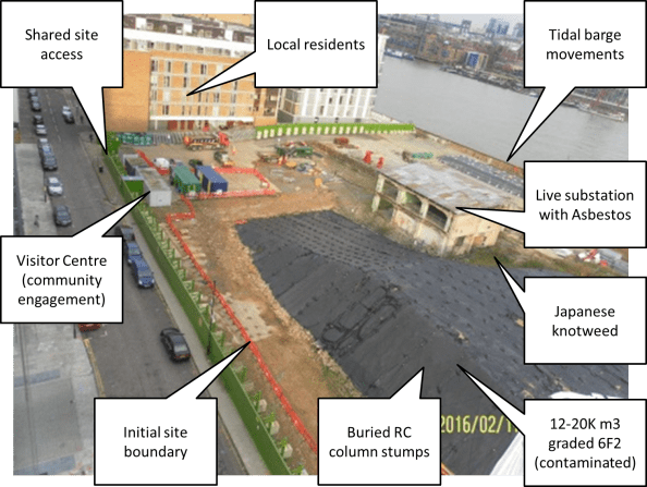
Figure 1. Site “Frictions”
Liaison with Neighbouring Works
This looks like it could be pretty messy. The initial CVB site boundary will roughly follow the line of the orange Chapter 8 fencing, CVB will control site access from the road and are responsible for security to the entire perimeter (including the parts within others PCs areas. As the stockpile is reduced we will expand our site (land/insurance permissions will take at least a week to be circulated before I can move a fence). Eventually we will get enough land mass to start work on the foundations for our office block (in the location where the green and blue containers are).
Local Residents
There are a number of restrictions on site activities owing to the clauses within the DCO. Noise planning and emissions will be closely monitored for all site activities. Residents have a 24hr hotline number to call if they have any issues with noise. We also have to maintain a visitor centre on site which we man on Wednesday evenings, and hold fortnightly Community Liaison Working Group (CLWG) meetings. The surrounding area is 50% expensive river front properties owned by influential characters (rumoured to include Captain Jean Luc Picard), and 50% social housing with a number of residents that are shift workers or unemployed and therefore in the property during working hours.
Stockpile Removal
Another contractor is responsible for removing the 6F2 stockpile from the earlier (2009) demolition works. Initially they had planned to load a 1000T barge each day, then changed this to two 500T barges. In the test run they managed to load most of a 500T barge within the tidal window before a hydraulic line burst. Consequently the estimate has been revised to one 500T barge per day. The works were further slowed by the discovery of suspected asbestos. Works to remove the stockpile have been halted since last Thursday whilst we await confirmation. Perhaps a coincidence but the asbestos was found by the contractor appointed to remove the spoil, and it could significantly increase their fee if the waste was reclassified as containing asbestos.
Concrete column stumps
The contractor also discovered that the stockpile is hiding a number of concrete column stumps (approx. 600mm sq). The removal of these is currently within ‘a scope gap’ between the different PCs, however if it falls to CVB to remove they will have to try and do it ‘quietly’, due to the restrictions of the DCO by progressively drilling and injecting an expanding composite to break down the concrete in layers.
Japanese Knotweed
An area of Japanese knotweed was discovered previously and has been receiving regular treatments, although it cannot be completely eradicated. This will eventually need t be removed to facilitate our new site access prior to the office foundations being constructed.
All of the above are fairly standard site issues within London, but nevertheless should generate some valuable learning over the next few weeks, and as I commented on Jo’s post, a lot of potential for neighbouring contracts to impact on our works. I should add that we receive a brief on the Contract Execution Plan on Friday so I hope to explore how we might deal with any delays caused to our project as a result of delayed enabling works under a separate contract.
Chambers Wharf
I wanted to do a blog about the issues that we’ve discovered on site, but then I realised that I haven’t actually written a blog to orientate people to the site. Therefore I’ll do two smaller blogs. I’m not planning on orientating people to the tunnel in general, unless people have specific questions, as it’s covered on the internet here http://www.tideway.london/the-tunnel/construction-sites/.
This blog will briefly introduce the site, and the following one will look at some of the issues in detail. This has the added benefit of not boring everyone too much, and boosting my blog numbers so that I can compete with Holtham and Nelson for the ‘Most Prolific Blogger Prize’.
I am attached to CVB JV (Costain, Vinci G.P. and Bachy Soletanche) who are delivering the Eastern section of the Thames Tideway Tunnel (TTT). I will be based on the main drive site located at Chambers Wharf and my first task is to coordinate the initial site works, to establish site and the temporary (until 2023) office and welfare facilities. The initial works will include utility diversions, demolition of structures including an existing substation, installation of welfare facilities (to be delivered by barge), installation of the cofferdam and demolition of the existing RC jetty. Once these works are underway we’ll have time to focus on the shaft excavation for the TBM.
Within the site boundary there are 2 other Principal Contractors currently working. One to clear the site following demolition works conducted in 2009, and the other to divert existing services and to install services for the Tunnel Boring Machine (TBM).
The phasing and integration of the different work packages works well on paper (figures 1 and 2 show how it is meant to work), but having attended two integration meetings it is clear that the programme appears to be moving towards one long critical path. The other PCs packages have been delayed by asbestos, noise and vibration complaints, and barge issues, and is starting to impact on the phasing of our works. I will expand on these site issues in my next blog. In the meantime, if our works are delayed due to other PCs failings I expect there will be some interesting contractual issues, but I will have to wait until the Contract Execution Plan is released before I can comment on this in more detail.
As the plan stands we will be establishing our own site on 21 Mar 16. Further than this, our progress is dependant entirely on the neighbouring contractors spoil removal, but with a good wind we will soon be starting works to the hoarding which is a not insignificant 3.6 – 5m structure supported by kentledge or posts, and excavating for the foundations for the modular office building.
The office modules are due to start arriving by barge on 21 Apr 16 and will be offloaded by a 100T crane, and then lifted in to place by a 200T crane. Simples!
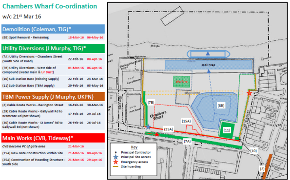
Figure 1. Site Integration w/c 21 Mar 16
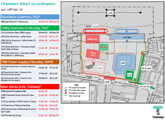
Figure 2. Site Integration w/c 18 Apr 16
Soil out and Props in
We have had a very busy couple of days on Hope St, the big props are now in on the North side and the Acid Suphate Soil (ASS) is being rapidly extracted. We excavated 1368 cubic metres yesterday and over 600 cubic metres the day before. The site is starting to look better and progress is being made. Everyone is getting gradually less stressed.
It looks like the working platform will work and there is enough spare capacity in the props and wailer to cope with the lateral loads from the excavators (but we knew this anyway). I thought the photos might help future students on Exercise Cofferdam. Note the splices in the props, the ramp for outloading dirt and the excavator pairs working in tandem. .
SIMPLE SOLUTION TO A SEEMINGLY SIMPLE PROBLEM?
So drilling through a basalt extrusion proves rather problematic when the drilling arm to your rig snaps off and you are unable to recover it. You are essentially left with a snapped arm 20m deep in what should be a 1500mm pile which is now unusable.
The piling subcontractors are on a design and build contract; they caused the problem, they will fix the problem at their cost. The solution, endorsed by the Multiplex team overseeing this part of the programme, is to concrete the original pile borehole (BP38) and construct two further piles (BP38-1 & BP38-2) either side of BP38, designed to carry the same loads. Simples!!
What risk did they fail to see?
The position of BP38 is close to a secant pile retaining wall which is approximately 3.5m from the site boundary. There is a heritage façade which sits on strip foundations on the site boundary which is already in a pretty ropey condition and only supported laterally. The northern retaining wall enables excavation down to Basement Level 1. The construction of BP38-1 & BP38-2 was designed by the subcontractor’s engineer; construction went without a hitch and the two 1200mm bored piles have sufficient resistance equal to the original pile.
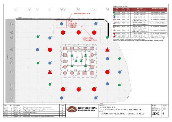
Position of BP38 in relation to site boundary and façade, and the northern retaining wall
Problem: It turns out that when you adjust the position and number of piles beneath a pile cap it alters the pile cap design. Funny that! The structural engineer (a consultant) produced a new design for a 1.6m x 5.4m x 3m deep pile cap to ensure the load (37MN ULS axial load) could be safely transferred to the piles. This means that an excavation of >3m is now required to construct the new pile cap. This is a >3m excavation in soft Coode Island Silt within 1.5m of the heritage façade.
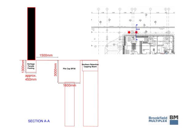
Cross section detailing the parameters of the problem
Unidentified risk: This is an obvious example of unidentified risk, which could easily have been identified. Two subcontractors responsible for two areas of design and construct have not communicated before adjusting construction plans due to a foreseeable problem – everyone knew the basalt was in that location. The geotechnical subcontractors have simply fixed the problem they caused, thereby fulfilling the terms of their contractual obligations, without due consideration for the next phase of the programme, i.e. the construction of the pile caps. Multiplex have ratified the change because, I would argue, the people overseeing the construction have not understood and/ or identified the second order effects of the change.
Discussions: The first time I was enlightened to the problem was when the co-ordinator (construction manager) overseeing this phase of the programme sat getting rather stressed at how he was going to solve it. After two hours of ‘it will be fine’ and ringing round for advice he sent me the specifics when requested to have a look at. Two heads are better than one.
Options on the table:
- It is obvious that the excavation cannot be conducted to that depth without retaining the ground which supports the façade. But the question was how? My recommendations:
- a) Stiff retaining wall functioning as a cantilever capable of withstanding lateral earth pressures and deflections (combi wall perhaps?). This would give clear space in which to excavate at the front of the wall but would require greater efforts to construct such a substantial retaining wall. Also very risky due to the absolute necessity that the façade cannot move.
- b) Prop a sheet pile wall using ground anchors so the load is transferred to the ground behind the wall. Due to the proximity of the boundary (<1.5m) I deemed this infeasible; there would not be sufficient space within the boundary to fix the anchors behind potential slip surfaces.
- c) Prop in front of a sheet pile wall bracing against the northern retaining wall. This is very feasible ensuring that sufficient space is retained to permit excavation.
- Review the pile cap design with the intent of reducing the depth of the pile cap and subsequent depth of the excavation. This may have been an option prior to the construction of the two piles, but unlikely to be feasible now the location of the piles is fixed. A retaining wall would still be required but to a potentially shallower depth.
The solution: I recommended Option 1c as the way to go, pushing the piles where possible rather than vibro. The piling subcontractors are responsible for the design and construction of any temporary works to enable the excavation but were holding off to receive direction from Multiplex. Multiplex in turn has sent the problem direct to the geotechnical engineer consultants for their advice. Their recommendation: Option 1c.
Timing: The problem was first identified by the groundwork subcontractor on receipt of the new design drawings of the pile caps. This was on Friday, nearly three weeks after the failure to construct the original piles. Construction of the pile cap was due to commence on Tuesday giving 1 working day to come up with a solution and have the designs authorised. Needless to say, it is now Thursday and the team are still waiting on the design from the piling subcontractors and work is yet to commence on the retaining wall.
Lessons learnt?
- Communication is vital when the work being conducted by one subcontractor affects another.
- Second + order effects must be considered prior to making any amendments.
- Identifying risk early and consider this risk in re-mediation plans.
Additional remarks: In this case, the solution would likely have still been the same had the problem been identified when the original pile was deemed unusable. The upshot of early identification was that a retaining wall could be have been designed early and constructed immediately after the piles, thereby causing no delay to the construction of the pile caps.
LSHTM Condensate Recovery Analysis
LSHTM Steam System:
My involvement in the London School of Hygiene and Tropical Medicine (LSHTM) steam replacement continues. I’d hoped that the design would be complete by now and that I’d be moving on to something else but there’s been a slight question 4 moment. But I’ll come onto that in another blog.
Intro
As previously mentioned steam systems generally consist of steam mains (flow) and condensate (return) pipes. Condensate is transferred from the steam main to the condensate pipework by means of a steam trapping station. The system we are putting in is mainly to supply autoclaves (sterlisers), but is also a backup supply for a heat exchanger if the normal LTHW boiler falls over. When the steam gets to the autoclaves it will transfer to condensate like in any load, except that in autoclaves the condensate is then contaminated and cannot be returned to the steam generator. This means that the only condensate available for recovery is from losses in pipework during running and warm up and cool down. Bryden Wood’s proposal which won them the job was to generate steam at high level (fourth floor), collect condensate and send it under gravity to low level (basement) and pump condensate back up to the generators in a separate pipe.
I’ve calculated that on a normal day LSHTM will use 10m3 of water for steam, 3% of this usage is due to running losses and is potentially recoverable the rest goes down the drain via autoclaves. What is less clear is what should be done with the condensate that is recoverable. Was the original Bryden Wood proposal correct? I was originally told that we were recovering condensate as it is best practice and the most cost effective method. This blog will cover some COA analysis on 3 possible options to deal with the condensate being recovered:
COA1:
Stick to the plan as described in the Bryden Wood proposal. This will require the installation of a condensate recovery unit in the basement. This is basically a tank vented to atmosphere which collects condensate that falls under gravity and allows it be pumped back up the building by means of an electrical pump. The tank is vented to atmosphere to minimise the possibility of cavitation occurring on the pump due to a sudden pressure drop in a liquid at high temperature. This plan is in line with common thinking associated with steam operation: always recover condensate. This is because by reusing condensate you don’t have to heat feed water up from 10 oC so energy is saved; you don’t have to pay for more water and also to treat more water. Although as highlighted above the system being put in place will only have 3% of the total steam used available for recovery. This leads to a saving of £1.81 a day by having a condensate recovery unit or a payback period of 7.5 to 17 years, depending on the type of condensate recovery unit, not including installation and running costs. Doesn’t seem worth it. However this does not factor in the back up heat exchanger. Although never / rarely used, if this system were to be used it would generated up to 600kg / hour of condensate. This then starts to have a more significant cost saving of £3.62 per hour. Although this saving is unlikely to impact the payback period as the heat exchanger would only be required to cover outages which would unlikely be more than a couple of days a year on average if at all. It still doesn’t seem cost effective to utilise. However one of the environmental requirements of utilising steam is that any water discharged to the foul drain cannot be greater than 43 oC. Condensate at atmospheric pressure will be just below 100 oC. If a condensate recovery unit were not used then another means of getting condensate away from the heat exchanger would be required or to cool it before going into the drain.
Strength:
- Provides a solution that is in line with industry practice.
- Allows system to drain fully on start-up and cool down avoiding water hammer.
- Does not result in hot condensate being discharged into the drain.
Weakness:
- Returning condensate does not offer a huge cost saving.
- A condensate recovery unit will take up space in the basement.
- An additional piece of equipment is required which will require maintenance.
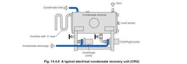
Typical condensate recovery unit.
COA2:
Rather than collecting condensate via gravity just put it into the existing drainage near to the steam traps where it is collected. This drainage is designed to deal with hot liquid from the autoclaves and should therefore be cooled by the time it gets to the foul drain. This goes against best practice, but is based on the fact that the assumption there is a cost saving of recovering condensate is flawed in this situation. Potential condensate from the heat exchanger would still need to be dealt with but this could be achieved by using a self-contained pump trapping station which would fit on the existing heat exchanger skid and utilise steam power to push condensate back up to high level. Unfortunately getting to the existing drains from the steam traps is easier said than done and will create a huge amount of disruption not to mention the requirements to install vent lines everywhere; when condensate that was at 6 bar g passes to atmosphere a large portion of it will want to flash to steam, therefore vent lines would be required to avoid pushing steam into the drain. Therefore due to installation issues this option was not considered any further.
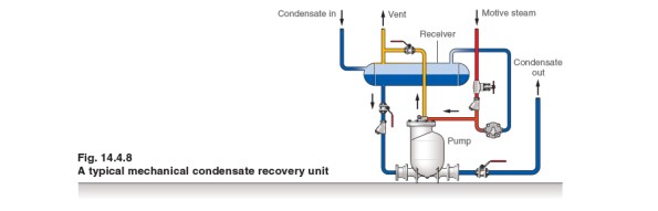
Typical steam powered condensate pump.
COA3:
Same as COA2 but rather than putting the condensate from the traps to drain utilise the pressure difference across a steam trap (6 bar on steam side, atmosphere on condensate side) to push the steam back up the building to the steam generators. The lowest steam trap is 16 m below the generators, so allowing for backpressure and friction losses there should be a net pressure of 4 bar to push the condensate back to the generators. However when the system is turned off and cools down the pressure across the traps will drop until there is not a net pressure difference. At this point condensate will not be recovered and will fall back to the non-return valves on the traps. When the system is brought back on the condensate in the pipes will rattle back to the steam plant potentially causing noise and damage as it goes.
Strength:
- Recovers condensate in line with industry practice.
- Minimises the amount of equipment in the basement.
- No running costs associated with an electrical pump.
Weakness / Threat:
- Water hammer and noise on start up.
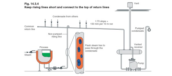
The left hand side of this figure shows a steam trap at the bottom of a process being utilised to lift condensate up to a common return line.
For this reason I’ve decided to stick with the original plan. This led me to question whether the exercise had been worthwhile. I believe it was. Although I’m not changing the scheme it’s always good to question what is put in front of you rather than accepting it blindly. Secondly I believe the reasons that I have come up with for sticking to COA1 are slightly different to the reasons why it was selected in the first place: I am selecting it based on it being a solution that minimises problems with respect to installation and running, whilst the original logic was that it was the most cost effective solution.
KNOWING YOUR ASS FROM YOUR ELBOW.
In my last blog entry I mentioned Acid Sulphate Soils or ASS. I have been put in charge of the safe disposal of the ASS. Not only does this help me cover the sustainable development piece for CPD but, more importantly allows me the opportunity to talk ASS whenever I want.

A heap of ASS. Note at the time these stairs were the only egress and the black smudges/ooze.
So what are acid sulfate soils? Here comes the Science…
Acid sulfate soil is the common name for soils that contain metal sulfides. In an undisturbed and waterlogged state, these soils may pose no or low risk. However, when disturbed or exposed to oxygen, acid sulfate soils undergo a chemical reaction known as oxidation. Oxidation produces sulfuric acid which has led to these soils being called acid sulfate soils.
How and where are acid sulfate soils formed?
Acid sulfate soils are formed by bacterial activity in waterlogged conditions when there is no or little available oxygen.
Naturally occurring bacteria convert sulfate (dissolved salt) from seawater, groundwater or surface water into sulfide (another type of compound that contains sulfur). This sulfide reacts with metals especially iron in the soil sediments or water column, to produce metal sulfides (the main components of acid sulfate soils). In order to convert the sulfate into sulfide, the bacteria also need a source of energy provided by organic material such as decaying vegetation.

So what I hear you say!
Well we have just dug up a lot of this soil, exposed it to air then added a good downpour of monsoon rain onto it and left it there to get really nice and acidic. Essentially any water we pump out has to be treated like sulfuric acid and needs to be neutralised. So you can imagine my joy when the bloke came to pump it out this morning then proceeded to let it leak out of his truck on the way to the disposal site.
For Damo!

This will be where the lime is added once the water tank has been moved.

The Water holding tank is in the top right hand corner of the picture and needs to be moved to the corner of the excavation to avoid stressing the wall.
I’m sure Greg told us not to start without a contract?
With an 80,000m3 hole in the ground, the Client has shown significant commitment to the ‘DUO – Central Park’ project, albeit with a different contractor! Brookfield Multiplex are now lined up to continue the project, but are yet to secure a contract. Although a contract is yet to be agreed, a site office has been established and considerable effort has been spent, along with $1 million, in preparing for the project. Before my arrival the anticipated start date slipped two months. Since my arrival it has slipped again, an unrelated matter I’m sure. Multiplex now expect to establish site in April and commence works on 2nd May. Confident that a contract will be reached, we are using this time to prepare for the task, refining the design on a daily basis. With such a rare opportunity to conduct such in depth preparations – nothing should go wrong once the work starts… right?
