Archive
Grease build up in Non Return Valves
BLUF: Can any of you geeks point me towards any discussions or case studies on the effect that fat, oil and grease (FOG) has on (NRVs?). I’m guessing it’s not going to be good but I need to know how bad it could be, maintenance periods, dosing options.
Background:
I’m working on the adaptation of the drainage for an existing department store in London. Over the years the store has developed a maze of drainage, both foul and rainwater, no-one really knows how it works and there is a history of FOG build ups causing blockages, and being London concern regarding rat ingress.
There are around 20 proposals to fix all the issues. Two of these are flap type NRVs to prevent rat ingress, and grease traps with a wider grease management process. However, there are areas where in the short term (2-10years) we will not be putting in grease traps for commercial reasons and so there is concern over whether fitting the NRVs to this section would make grease problems worse. The store doesn’t have a great record of maintaining the system so “just check regularly to prevent blockage” probably won’t be successful.
Optimistically I’m hoping that the pressure required to operate the valve may be enough to clear any FOG build up but I guess this would depend on what volume and the frequency of flow, and what type of valve we specify.
Innovation. The conclusion of the trilogy.
The long awaited concluding part to the innovation trilogy. Spoiler alert – RF was right. It’s about risk appetite and opportunity. Feel free to stop reading now if you can shout that at the reviewers with enough confidence to convince them you know what you’re talking about. If you want a bit more information up your sleeve then see below. Alternatively wait until Disney buy the rights to make the Innovation Trilogy and then watch the film.
Most of this is based on discussions with the authors of “Innovation in Structural Engineering – the art of the possible” published in The Structural Engineer Jan 2017. I won’t cover the report in detail as i’m sure you’re all keen to read it. I also sit on the Expedition Sustainability Group (SG) with two of the authors, and we’ve discussed some of the wider issues in our meetings.
To quote the US Administration and Tom Clancy….”there is a clear and present danger [from innovation*]”. (*also drug cartels but that’s for another day). Therefore Clients are wary of it and there must be a demonstrable benefit (potentially T, Q or C). The sustainability group believe that to implement innovative solutions they need to contribute to both innovation (pushing the boundaries) and sustainability. I think they missed out the key requirement and that it also needs to be functional. If the proposal falls within all 3 of the circles below and has monetary saving it will be difficult to argue against.
![20170211_132843[830].jpg](https://pewpetblog.com/wp-content/uploads/2017/02/20170211_1328438301.jpg?w=595)
One of the authors (Jones) presented his research to the SG. He thinks whether innovation can be realised or not can be expressed as below:
Initiator + Enablers = adoption
Requirement, constraints, Resources, skills
aspirations
The article cites earlier research suggesting that likelihoood of adoption primarily depends on five factors:
- Compatibility – how well does the innovation work with what already exists.
- Complexity – how easy is it to understand the innovation.
- Observability – can the success of the innovation be visually demonstrated. (In the case of SNFCC literally jumping up and down on one of the prototypes was one of the most effective demonstrations – despite being completely unscientific)
- Trialability – Can you safely test it or is it just a punt
- Relative advantage – How much T,Q,C is improved
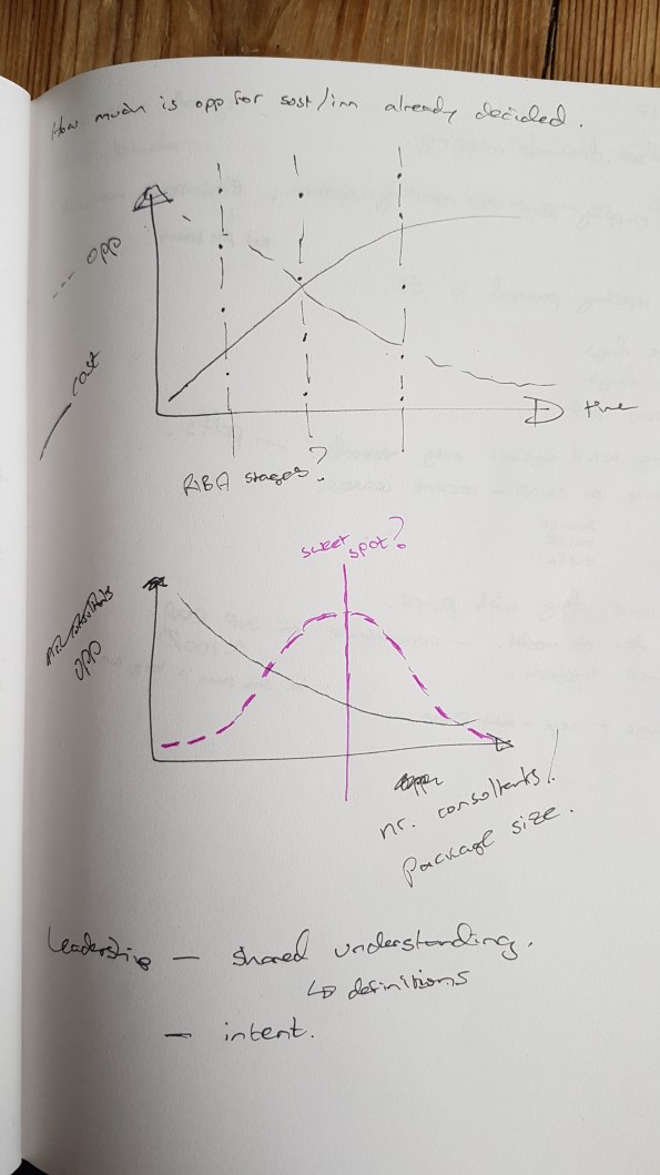
In addition, as I mentioned before, there are unintended contractual barriers. Many innovations may not be realised due to the Client/QS and the way they have tendered the works. We will all be familiar with the opportunity for change versus cost of change graph (top graph below). I think this can be applied to innovation and that right of where the two lines cross, you’re unlikely to see an innovation unless the saving is enormous. Depending on the nature of the contract, the amount of D&B, the size of the packages and when they are tendered, the position of this crossing point, in conjunction with the RIBA stages, will change. The lower graph shows my thoughts on the number of consultants/number of packages. Initially I thought that the more consultants or specialists you have, the smaller their packages of work will be, and the less opportunity there is for innovation. On reading the innovation article, I then revised this to suggest that there might be a sweet spot with enough specialists for a broad range of experience and knowledge, but still maintaining a large enough brief to be able to make savings within each tendered package of work. Put bluntly, why would one designer make a change that would benefit another consultant or contractor’s work package.
Of the 5 factors listed earlier, trialability is the most interesting to me because I had no idea how this would be approached in a military engineering context. It was also one of the biggest challenges on the Stavros Niarchos Foundation Cultural Centre (SNFCC) project., when they wanted to use ferrocement to provide a thin canopy on top of the building.
The team highlighted 3 methods of trialling. The cheapest is to look at other industries or projects that have implemented something similar, proving the material in a different context (or perhaps even the context with a different material? but this is trickier and less likely). This leaves a gap which needs to be bridged with supporting calculations, and is therefore relatively risky. (I think Concrete Canvas have found it difficult to progress from this option to the next option)
The next option is to combine physical models, computer analysis, and prove the innovation from first principles. The level of proof and risk with this option varies massively. Generally the more physical and less conceptual the analysis, the more you can tick off complexity and observability. Providing, that your modelling assumptions are correct.
The final option is to gain certification of compliance through formal testing against specific performance requirements. This is expensive and often outside the scope of an individual project, but can deliver a good level of confidence and consequently a low risk of failure.
The successful SNFCC project used all 3 of these approaches. With the above in mind does anyone know if we used any of these techniques on operations or on PDT?
The SNFCC canopy innovation was ultimately successful because it had the right project team, but this was not an accident. The Client was actively seeking out innovations and had a budget to support this. Expedition understood the intent and set about to secure a team of academic and industry experts to support them in their quest. The project was tendered competitively with the project team demonstrating a viable construction solution to potential contractors. This meant that there were less unknowns, and therefore risk for the contractors to have to price.
The so what for me is that I don’t think i’ll come across many clients actively seeking innovation in the next few years. However, I might be forced to implement innovations to overcome other barriers. If this is the case then i’ll need to decide upon and implement a testing/proving process to demonstrate management of the risk, and a real benefit. I’ll also need to have access to the right team to support me, which means understanding the reachback to 170, academic staff, the wider Corps and the invaluable Engineer Staff Corps.
Expedition is considering forming a technical working group to investigate the potential for reducing the partial safety factor for reinforcement, and safety and material factors in general, following a recent academic paper by Beeby and Jackson. I’m hoping this will allow me to develop a methodology for evaluating some of the safety factors used in military engineering.
Efficient Detailing of PT
My boss has buggered off to Melbourne for a couple of days and so I am having to seveerly raise my game.
I am looking at detailing a slab and found this usefule- please see attached link on guidance on efficient PT design. PT Detailing
TC Design – Practical Application of SA Techniques
It’s been some time since my last blog as I was away for a bit on holiday, it was great to see everyone out in Oz. I have now been back to work for a few weeks and am safely embedded in the Robert Bird Group (RBG) Construction Engineered Solutions (Temp Works) Team. I asked to go into this department in the hope it would allow me to get plenty of short, sharp tasks that would expose me to a broad range of experience whilst developing my SA skills.
Currently I am designing an embedment plate for two Tower Crane Ties. The example below shows one of the double brackets specified by Terex that I need to connect to the embedment plate I come up with.
I was given un-factored reactions, also by Terex, all of which are acting at point A as annotated on the second Dwg.
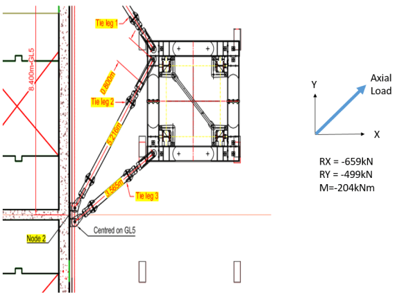
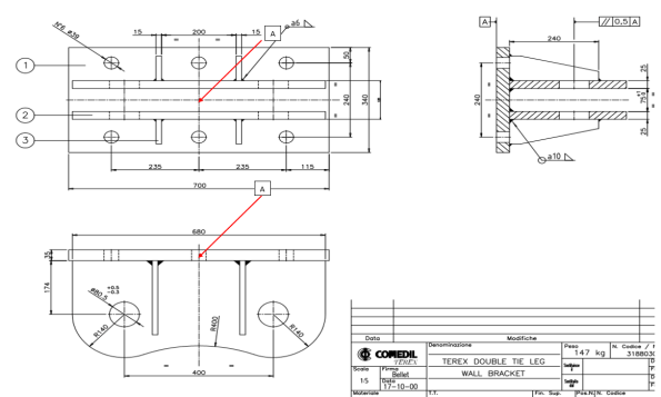
Put simply, I am trying to transfer the loads given into my reinforced concrete core wall. I started by factoring the reactions and conducting analysis on the back of the bracket to determine the maximum tensile loads likely to be seen in each bolt position (36mm dia bolts). Ideally my anchorage re-bars will tie into this plate with couplers that connect to 36mm dia bolts protruding through the holes you see on the dwg, also giving me the tensile load in my anchor rods.
For those who are bored or, particularly for those currently on phase 1 who enjoyed the SA exam twice like I did, it’s a good problem to get a feel for how the technical analysis skills you are taught on phase 1 are used daily in a structural engineer design office. Even after 11 months on site watching Irish blokes pour concrete it didn’t take long for me to get back into the swing of this stuff and weirdly, I’m now actually starting to enjoy it.For obvious reasons I was mildly apprehensive about this phase of placement but as it turns out I find it much easier now I can apply it to real world work.
I’ll try put up some of my workings in a few days but as a starting point you clearly need to design a solution that deals with all the forces acting on the bracket in this condition. The means by which you model this bracket significantly changes your loads. (Note: I also resolved this with the axial force in the opposite direction shown but as it gave a very favourable pre-stress the tension issue is negligible in that condition).
(Once you’ve done it using all three rows of connection points, try deal with the moment using only the central two bolt positions as this is a design constraint I am working through at the moment due to the geometry of the core wall).
Australian Structures Codes Cheat Guide
For those that are struggling with the Oz codes for detailing reinforcement or are shortly to deploy – I was struggling with lateral reinforcement for a prestressed bar to tie in a crane. I found this excellent presentation. It has certainly helped jog my memory.
‘Expectations for those heading to Australia to work for Multiplex’
1. Multiplex have an excellent reputation in Australia for being a ‘fair’, reputable builder. They aim to employ good people, pay well but expect a lot!
2. It is highly likely that middle management will expect 12 hours + per day. Get stuck in, but set your stall out from the start. My priorities were academic work, gaining varied site practice and experiencing Australia – not working all hours to get my line manager promoted.
3. They push the contractors hard. Some bully, some build relationships, which was interesting to observe.
4. They work in fast paced environment. I found processes, general administration and management of pers to be lacking in comparison to what I’m used to. They were clearly focused on building stuff on time and making money $$$$ !
5. What we consider as unethical practice happens every day on site! (in WA anyway)
6. Attitudes towards health and safety can be extremely varied. Be mindful of the term “that’s a Saturday job”.
7. Workers unions are very strong and powerful in Australia. The majority of Multiplex projects are union sites which present their own management battles.
Give me a bell if you want to discuss anything further: +61 498 145 474
Playing the blame game
My old site BCT – just seems to be the baddie in a 1980s B movie – it just won’t die. Every week brings a new issue that needs rectification. Multiplex are expecting to make a $20 Million loss on the project.
I am spending a lot of time conducting what I call ‘Post Mortems’ on projects. Each one could be a TMR by itself and can be depressing/interesting depending on how morbid your curiosity is. There are a lot of firings going on and these Post Mortems are make or break for some people. My boss described it thus – we don’t fire them ourselves we just put the ammunition in the gun. Monday saw an interview without coffee for the main players in the BCT project team. Why is your project already $1.5 M over budget in reo and you have only just come out of the ground? Below is an email of my assessment of the reo overrun sent to my oss :
The facts of the situation are these:
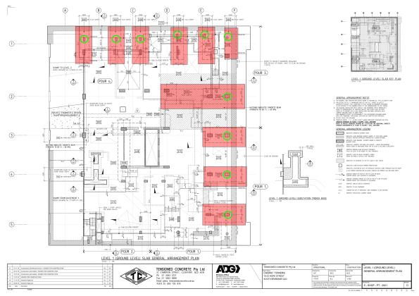
- Projected versus Actual. The greatest increase in reinforcement has occurred at Level One with approximately 6.5 times the reinforcement projected( 107 T against projected 16.2 T). The majority of this reinforcement is in the transfer beams on Level One (84 T). This leaves approximately 23 T of reinforcement in the remainder of the Level One slab (not including mezzanine).
- The transfer beams were added due to issues with the basement retention system. The original design called for pad footings close to the secant pile wall. However, because the secant pile wall was not deep enough in the North and East of the site, there was concern that the footings close to the wall would undermine the bottom of the wall. The decision was made early to remove the pad footings rather than issue the piling contractor with a variation. Subsequent consequence analysis seems to have been focussed on the geometrics and car park spaces. There appears to have been no formal consideration of the cost impact of the additional transfer beams. As a rule of thumb, one transfer beam costs approximately $35,000. The decision to remove the columns in the basement and use transfer beams resulted in an extra 10 transfer beams (approximately $350,000).
- Contract Award. There are no transfer beams included on the Level One sketch in the Post Tension tender documentation. While the transfer beams are shown in the capping beam documentation in S-CD-09-001 Retention Wall and Capping beam Plan, this information was not transferred to the Level One drawings. There appears to have been no tracking of the transfer beams on a design register and it does not appear to have been communicated to the sub-contractor effectively during the tender process.
Assessment. The existence of the capping beam drawings muddies the water somewhat. On one hand the sub-contractor should have been aware of the need for transfer beams from the capping beam drawings but, could argue that it was not covered by his scope because it was not on the drawings of Level One. There were several failure of process within the Multiplex team.
- Failure to communicate the addition of the transfer beams with up to date drawings prior to contract award.
- Failure to understand the second order consequences of removing the columns in the basement (Cost).
Regards,
Doug
Having thought that the PT designers had got the message about putting too much conventional reinforcement in the slabs, I received the new drawings for Podium Level 2. The previous iteration had approximately 60 T ($120,000 over budget for level 4) of reinforcement over what had been agreed in the contract. Having worked late into the night to get an answer to the project team on the savings and ground truth of their design I was disappointed to discover this iteration had shaved a meagre 15 T off that figure ($30,000 saving). Not good enough Mr Consultant show again!
In other news I have been playing around with STRAND (finite element analysis software) trying to assess the natural frequency of a 20 m span conventional reinforced concrete beam. The beam is supporting a swimming pool above the ballroom at the Jewel Hotel on the Gold Coast and there is concern that the chandeliers could swing around because of the vibrations from the pool. It’s not urgent but its fun to play with when BCT gets depressing.
USACE Funding Model
Introduction
Well, it’s been a little while but I though now was as good a time as any to jump back into the blog-o-sphere. Like everyone else I’m in a design office, the work isn’t too bad despite having to do all my calculations in strange units of measurement such as inch-kips and force-lbs; which means that I don’t really have any idea what answers I’m expecting to get. No change there then!
I’m still working for USACE, but the commercial environment is like something halfway between a commercial company and a non-profit government organization [sic]. I’ll do my best to outline some of the budgeting and funding principles below:
The Military Design Branch (where I’m now based) is an arm of USACE that essentially carries out design work on behalf of the Baltimore District. Despite being a Corps of the US Army, USACE are not entirely publicly funded, and are required to cover their own overheads (including wages) by charging a fee for their services on any projects undertaken. Legislation prevents the military from making a profit; however this arrangement means that the organisation is run somewhat like a business, with Districts required to break-even within a 1% margin. Performance (profit) is reported up the chain, with Divisional Commanders having the authority to support under-performing areas. Commanders are therefore required to effectively manage income and expenditure whilst aiming to hit the 1% profit target, after which any profit achieved (over 1%) are returned to the US Treasury.
MILCON Program.
The MILCON program is funded directly by the Senate, with budgets set on an annual basis according to performance, budget, program progress and projected work. All USACE costs associated with the planning, management and design of projects is taken directly from this source. There is therefore only a finite amount of work that districts can pursue, and it is usually delegated to divisional chiefs to determine which work/projects they wish to undertake according to the resources available to them. However, the final decision remains with the District Commander. Any remaining MILCON program work will then be sub-contracted out to commercial Consulting Engineers (I did an outline design for a one-storey VCP before being told it had been put out to tender!). The direct result of this arrangement is that clients operating within the MILCON framework have no direct say in who conducts the planning, design and management of their own projects, which is often determined by the capacity of the local USACE district office.
Construction Funding
The Senate annually funds the MILCON program, however these finances exclude the costs associated with new construction projects or renovations, instead clients apply directly to the Senate for these projects. A formal bid process is initiated approximately two years prior to the anticipated project start date, whereby project scope and justifications are submitted and the bid is accessed against pre-determined government metrics. If approved, funds are released directly to the client, and used to cover construction costs (e.g. the JOC project). As previously, this means that the client generally has a choice as to which organisation will ultimately administer their own construction contract, however USACE are generally ‘chosen’ because of their reputation and specialist knowledge. In order for USACE to then meet the overhead and wage liabilities of the project delivery team a ‘supervision and administration’ fee is then charged back to the client. These fees are generally charged at a standard rate of 5.7%. As a hedge against poor performance by the contractor or unforeseen events/variations USACE will also typically also apply a 5% contingency value to the overall construction cost, as per the diagram below.

Contract Relationships
A fixed price contract model is employed on all Government projects, and the client is legally obliged to compensate USACE for all work conducted. However, at the outset of any project a one-off contract is negotiated which includes rates and fees for all design costs, management, profit and overheads. Contract ‘variations’ however are always subject to inter-party negotiation, which due to their uniqueness and un-foreseeability are not agreed prior to the commencement of work. Disputes or claims that arise from variations can and are still subject to legal proceedings and/or arbitration. However, the Government’s policy of ‘fair and reasonable’ treatment generally ensures that most of the Principal Contractor’s disputes are settled prior to reaching court. This policy can benefit both parties, however first-hand experience has demonstrated a willingness for the Government to concede positions to the Principal Contractor that they could reasonably have argued and won. My observations were that the Contractor usually came off better because they threw the toys the furthest!
Innovation in construction materials
3-2-8-cc-defence-1604 cc-other-sandbag-reinforcement-1604
I attended a presentation before Christmas from a company called concrete canvas.
“Concrete Canvas Ltd. manufacture a ground breaking material technology called Concrete Canvas that allows concrete to be used in a completely new way. Concrete Canvas was originally developed for the award winning Concrete Canvas Shelters, a building in a bag that requires only water and air for construction.
Concrete Canvas is a flexible concrete impregnated fabric that hardens on hydration to form a thin, durable water proof and fire-resistant concrete layer. Essentially, it’s concrete on a roll.
Concrete Canvas Shelters are rapidly deployable hardened shelters that require only water and air for construction. A CCS25 variant can be deployed by 2 people without any training in under an hour and is ready to use in only 24 hours. Essentially, CCS are inflatable concrete buildings.” (http://concretecanvas.com/).
I think they also featured on Dragons Den but didn’t get funding. I think it’s a great product. The shelters could perhaps be beneficial in longer term displaced persons camps owing to the fire resistance, although the market has been a lot less interested in these potentially (I assume) down to the increased cost, logistics and complexity compared to canvas/plastic alternatives.
On the other hand, the canvas rolls have sold very well worldwide, as it is a much cheaper alternative to reinforced concrete for non-structural applications, and is cost effective even when the cost of shipping to Australia is included (although this reduces the environmental credentials). Costain have used a lot of this stuff for lining ditches, stormwater channels and ponds, and bunds. The EA have used it for flood defences, and they also report the military have used it in Afghanistan (I think for improving Hesco and ditches).
The company has secured compliance certificates for fire resistance, age testing, abrasion resistance, chemical resistance, and impact resistance (for pipeline coatings). The use of the product in non-structural applications supports product development by allowing them to secure the accreditation above, provides funding and increases market awareness. But their ultimate aim is to push the product as a structural application. Due to the increased risk this poses, there are many more barriers, and more checks and balances required. It’s easy to get something into the non-structural market, essentially just prove that it won’t kill fish and newts. Proving that something won’t fail and kill lots of people is much harder. The future is also uncertain for manufacturers – will Brexit change the nature of BS EN accreditation, raising the bar or making investment in securing accreditation now irrelevant in the future? The Institutions say not – but who knows for sure?
Blog 3 – the third and potentially final blog in the Tony Strachan innovation series will look at the Stavros Niarchos Foundation Cultural Centre and how innovation was achieved by Expedition (and others). This featured in the January 17 issue of The Structural Engineer in case anyone wants a spoiler of the article I will be shamelessly presenting.
Update: I checked the info that concrete canvas sent through ref the previous military uses for their product. The case studies are linked at the top (as it’s the only place wordpress will let me put it) for info – but don’t let them stifle your creativity! I’m not aware if they’re working on military projects currently.
