Inadequate Toe Bearing in Permanent Cased Bored Piles
Since June 2016, one of my tasks has been to track progress for the solution to the bearing capacity issue faced on the Rail Bridge cast-in-situ permanent cased bored piles. The testing methodologies to find a solution have given me experience in a full repertoire of sequential testing procedures. Bit of a lengthy blog but gives a good insight into pile testing. I would be interested to see whether you would take the side of the sub-contractor or the client?
Background
The new Rail Bridge through the Airport East site is supported by 6 large diameter permanent cased piles, P1 and P2 are 1200mm dia supporting Abutment A, P5 and P6 are 1200mm dia supporting Abutment B and P3 and P4 are 2500mm dia at the central pier, refer Figure 1 below. All the piles are designed in toe bearing alone and have 500mm rock sockets within Class IV sandstone.
The SLS design axial load for the abutment piles is 7.4 MN. For analyses of high-strain dynamic tests, this value was increased to 9.0 MN to account for potential future negative skin friction on the piles. The ULS design axial load for the abutment piles is 10 MN. With a geotechnical strength reduction factor of 0.52 applied, a design ultimate geotechnical strength of 19.2 MN is required (= 10 MN / 0.52).

Figure 1 – Plan view of Rail Bridge pile layout
Concerns over the fractured sandstone allowing groundwater to seep into the piles required a wet tremie pour to be adopted. Following the completion of steel casing installation (Figure 2) and following excavation, water was pumped into the casing up to the water table level to maintain positive head prior to the concrete pour. The positive head aimed to reduce the in flow of sediment from ground water flow.

Figure 2 – Permanent casing being driven during an airport possession, note the railway line has been slewed to allow for works.
Sonic logging tubes were attached to the reinforcement cages, these were kept 200mm off the base of the reinforcement cage, 300mm from the toe of the pile.
During installation of P3 and P4, the 2500mm dia piles, the 16mm thick permanent casing buckled, resulting in a bespoke reinforcement cage being required.
Prior to the concrete pours the reinforcement cage was removed from the hole to allow the base to be cleaned. The piling rig using a cleaning bucket removed any loose material at the pile base. This also agitated any sediment causing it to go into suspension prior to the pour.
The tremie was lowered below the water line to the base of the pile. As the level of the concrete in the pile increased the tremie pipe was withdrawn in sections ensuring that a minimum immersion of 2-3m of the tremie pipe remained in the concrete at all times.
Pile Testing
Cross-hole sonic logging (CSL) was used to assess the integrity of the piles. A primary advantage of CSL is that it can assess the integrity of piles at depths which may be beyond the capabilities of sonic echo testing. It is probable that a large number of piles will include defects of some sort. The important consideration is that these defects will not materially affect the structural performance of the pile. The CSL assessment detected 15 issues of ‘Poor/Defect’ anomalies at a depth of approximately 35.6m – 36.1m below the top of concrete in P2 and 4 issues of ‘Poor/Defect’ anomalies at a depth of approximately 35.6m – 35.7m within P6. Further tomography assessment of P6 at 35.7m concluded that only 40% of the cross-sectional area of the pile comprised of 40 MPa concrete.
Core drilling of the piles was then recommended. On attempting to drill and core P5 the subcontractor made 4 attempts to reach the bottom of the pile without success using a percussion drill with a 100 mm diameter tungsten carbide head. The helical reinforcement was damaged during these attempts as it was struck by the carbide head. It is assessed the drill head maybe wandering during drilling due to potentially softer section of concrete due to removal and reentry of the tremie tube. P2 was successfully cored, the sample revealed what appears to be a 50mm layer of loose coarse aggregate from the segregation of concrete at the toe between sound concrete and the sandstone rock socket.

Figure 3 – Coring samples from P2. Note the aggregate in Core 3.
The toe of the core was cleaned using air to show the extent of the void. The void was measured at 400 mm at the base of the pile and a photo is shown in Figure 4 from a CCTV recording of the core. The coring holes and toe void were grouted, and subsequent CSL showed some improvement.

Figure 4 – CCTV photo shows the void at the base of P2, slowly filling with ground water.
P1, P2 and P5 were high-strain dynamically tested using a pile driving analyser (PDA) to check the mobilised capacity. The mobilised capacity of P1, P2 & P5 exceeded the required capacity. A guide to structural integrity and performance of the pile is given by considering the energy of the hammer blow delivered to the pile by the 20 tonne drop weight (Figure 5). The piles subsequent responding mobilisation capacity and estimated static deflection at mobilised capacity was much less than the allowed movement of 85 mm. The temporary compression of the piles under dynamic loading ranged from 8.1 mm to 9.9 mm with a 1 mm set.

Figure 5 – High-strain dynamic testing hammer on P1.
The pile resistance is subject to input data, primarily including Young’s Modulus and the Damping Constant. Corrected values of Young’s Modulus are correlated with signal matching from CAPWAP (Case Pile Wave Analysis Program) testing which estimates the total bearing capacity of the pile. The CAPWAP results showed the concrete over the length of the socket is a lower modulus than the upper concrete in the pile.
CAPWAP results showed a reduction in the axial stiffness at the base of the pile (i.e. the material at the base of the pile has a stiffness lower than that of “good” concrete). Also a reduction in the pile cross-section at the base of the pile (i.e. there are zones of contaminated or “poor” concrete at the base of the pile).
The Client – Roads and Maritime Services Conclusion
‘Whilst the dynamic analysis provides a pile capacity at this point in time, the uncertainty of the size of the voids and / or quantum of the integrity issues, coupled with the poor integrity section not being fully contained within the sandstone rock socket or the steel pile casing, results in the Principal being unable to determine the extent of any future pile settlement over the design life of the structure.’
Conclusions & Recommendations
The pile should only be considered defective if it does not meet the SLS or ULS requirements. The client has rejected the piles due to the defects with in them despite them still passing the relevant criteria. They have decide to replace P1, P2, P5 & P6, this time using a dry tremie pour, by achieving a seal between the permanent casing and the rock socket.
The reason for failure of concrete in the toe of the rock socket has not been fully concluded. After gaining a better level of technical knowledge on the subject by reading Tomlinson & Woodward, Pile Design and Construction Practise, 5th Ed, Section 3.4.8 discusses the issues related with groundwater in pile boreholes. It mentions, ‘a strong ground water flow can wash away concrete completely’. In cases of strong inflow, ‘the water must be allowed to rise to its normal rest level and topped up to at least 1.0 m above this level to stabilise the pile base.’ It does directly mention this with cased piles but, honeycombing of concrete could certainly be an issue.

Figure 6 – Example of a defective shaft of a bored pile caused by cement being washed out of unset concrete (Tomlinson & Woodward, 1977)
Despite the piles having permanent casings, ground water flow through fissures in the sandstone could have caused the grout to wash out of the concrete, leaving the aggregate in the base of the piles. Grout leakage could have occurred in the tremie pipe during delivery leaving insufficient grout to bond the aggregate. The tremie pipe may have been too far from the toe of pile on concrete delivery causing separation of concrete on delivery.
A dry tremie pour with a high artesian head in the sandstone through fissures could cause the same issues to occur. John Holland have now mitigated risk by the client providing both a methodology and load values required in the piles, with the sub-contractor paying for reworks.
Photo for Comments Section
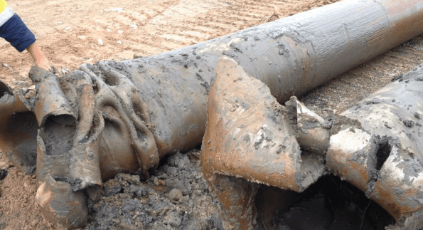
Figure 7 – Plastic deformation of a pile casing driven past refusal

A good blog James
A few clarifications:
A rock quality IV is nominally a ‘POOR’ rock ; there a some 7 metrics that contribute to this rating; discontinuity spacing, joint condition , groundwater (none to flowing) and sop on. So just using a rating to consider a rock can overlook the actual risk.
I like the core box photo it perfectly demonstrates the problem- the yellow/buff material is the sandstone into which the pile is socketed.
To explain the dynamic testing; a pile head velocity to and impact is recorder as a wave response; CAPWAP software tried to match this response in a software pile model by adjusting the soil/pile response parameters until the computed wave matched the measured wave.
The idea of a thixotropic piling fluid is that , at rest, the fluid ‘sets’ and has a higher density than water. It is easier to balance seepage pressures
One of the things that can happen if water balance is used if that if the tremie is surged up and down during concreting a flow can be induced at the base
I am intrigued – how is it proposed that these piles are replaced?
Hi John,
It has been concluded by the designer that the 1200 mm dia pile is acceptable in bending but not axial loading. For design these piles will be ignored to resisting axial loads. All four abutment piles (2 at each abutment) are required to be replaced.
Two pile types were considered, an H section pile (reading the description it sounds like a plunge column, similar to what Jonny Linares was using as it is encased with concrete) and a permanent cased bored pile. The piles that were considered are:
900mmφ tubular piles x 20mm wall with a 1000mm long shoe, 50mm thick
1200mmφ tubular piles x 20mm wall with a 1000mm long shoe, 50mm thick
H section piles 500WC440 with a 500mm long stiffened section with added 18mm plates.
The designers have stated they require a 500 mm socket in Class III (moderately weathered, medium strength) sandstone, as it is characterised as having between 30,000 and 60,000 MPa end bearing resistance mobilised through driving. As you stated the Class IV is inadequate. The designers previously didn’t provide a high enough energy to drive to the Class IV, the NPT value of 60 was too higher resistance. Also, after the 16mm cases on the 2500mm dia piles buckled, a similar situation could have happened to the 1200mm dia piles, see Figure 7 (just added in the main text). Typical refusal set is 2.5 mm per blow (at a nominated energy). Tighter refusal sets are being nominated at 1 mm per blow.
The piles will be subject to combined axial and bending moments resulting from frame actions, including the second-order design bending moments. An elastic buckling analysis was performed in MIDAS Civil to determine the critical buckling load case. Euler’s critical load was determined. The H sections require plates for loading in the socket.
The 900 mm diameter pile has been chosen as the most appropriate solution as the bearing area achieved at the toe is significantly larger than the one provided by the H section and offer construction program advantages over the 1200 mm diameter piles.
The end bearing capacity of the Class III sandstone has been reverse calculated from the pile driving and PDA testing carried out on the recently completed Barangaroo Ferry Hub (Sydney Harbour) project, where similar size permanent cased piles were driven into Class II-III sandstone.
The new piles will be 3000 mm centres from the original 1200 mm dia piles. The new 900 mm dia piles will also be 3000 mm longer to achieve the Class III rock socket of 500 mm.
I thought about the use a polymer piling agent, but despite the polymer having advantages of disposal over bentonite there is still the issue of contaminated ground water, which makes disposal of anything on site much more costly.
Interesting stuff mate. Dynamic load testing (DLT) was completed on my site for the foundation piles in order to increase the geotechnical strength reduction factor.
The requirements for testing are determined by the ‘Average Risk Rating’ (ARR) in AS2159. The ARR considers various risk factors including site ground conditions, installation procedures and design. The risks are weighted accordingly. The AS says that if project ARR is below 2.5 then no testing is required. The ARR also determines the geotechnical strength reduction factor which is then used to calculate your proof load criteria. (Limit state load Ed / Geo reduction factor (g) = proof load).
Interestingly, Keller completed the assessment at my site and assessed the ARR to be 2.45, thus (just) removing the code requirement for load testing the piles. However, they still completed 2% testing using PDA and CAPWAP in order to increase the geo strength factor to 0.63 for design purposes and I sense to confirm their aggressive design approach. (0.48 strength reduction factor to be used if no testing completed)
Your Geo reduction factor is quite low, indicating a high risk rating. Who determined the ARR for your works? And what was the total mobilised resistance from testing vs Ed/g?
Also, from a contract perspective, who has rejected the piles? The ultimate resistance on the piles at my site were fairly close to the proof load required; 8.9 MN (resistance) > 8.8 MN (from Ed = 5500 / 0.63). This was approved by MPX’s structural consultant as part of a D&C relationship. However, a construct only might have seen a different outcome, given how the ARR and geo reduction factor determined by one of our subcontractors is very subjective (i.e. higher ARR = geo reduction factor of 0.52 as on your site…..8.9MN < 10.5 MN. If my risk rating was same as on your site then piles would've failed and been rejected). If it's a construct only then surely the piling specification, testing requirements and design values are all determined by the principle's consultants. Otherwise it's your bag and your consultants/subcontractors.