HV Transmission Lines – RFI
G’day all.
This is mainly a request for help should anyone know of a solution or encountered a similar problem before.
Context
I am working on the Mernda Rail Extension Project (MREP) in Melbourne in the rail construction team for John Holland. The main items of my scope are in the delivery of the traction power to run the trains. This includes three new substations, overhead delivery of traction power and the installation of a new 22kV distribution network (underground and aerial).
22kV distribution
The bulk supply points for the Mernda project are the AusNet Epping Zone Substation and AusNet South Morang Zone Substation. AusNet are the District Network Operator (DNO). The 22kV supply between AusNet zone substations and the traction substations is via cable. The majority of the supply is by underground cable between traction substations, with the exception of a section of aerials (with a small cable section) between Epping and Hawkstowe Traction Substations. The general network arrangement is provided in Figure 1.
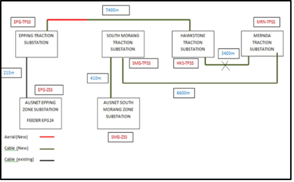
Figure 1 – 22kV Arrangement
The Ariel transmission, depending on its location, be it in the rail corridor, residential area or on a shared user path (walkers and bikes) has different pole types, namely steel or concrete. The choice is driven by cost, construction time and the design standards.
The Rail Operator has stipulated that design must meet standards AS 2067 which includes reference to Standard AS/NZS 60479.1 for calculation of levels associated with the risk of heart fibrillation and Standard ENA Doc025, EG0 providing guidance in establishing risk level.
The bottom line is that the required earth grid resistance of 5 ohms cannot be achieved in all areas using the Rail Operators standard earthing arrangement. This is mainly due to the fact that we have solid rock 300 mm below ground down to 10 m deep along the entire site, which is not great due to the high resistivity levels, which are well over 100 ohms at all locations with the worst being 200 ohms until you get below the rock.
There are 32 concrete poles shown in figure 2 that are in public areas and need the earth grid to achieve 5 ohms. We cannot get to the 5 ohms for any of the poles and just to get near this we would need multiple 10m+ earth stakes at each pole. Not a cost that the project or the rail operator wants to entertain.

Figure 2 – Concrete pole dimensions
Therefore, there are two options for a solution going forward:
1) Apply a probability assessment in accordance with Guide ENA EG-0 referenced in AS2067:2016. – This has been flatly refused by the rail operator.
2) Cladding poles with an insulating medium to a height of 2.4m to mitigate the possible Touch Voltage hazard to meet the requirements of AS60479.1. – This is the preferred option.
Question
My question after being unable to find a product that can conduct the role of “cladding the poles”, does anyone have any experience with this issue and know of a product, or a possible solution that has not been considered?
If there are any other questions about the project, traction power, substations or work in the rail environment I will try my best to answer.

Run another cable through as an earth and ground it at one location. Not cheap but better than multiple10m earth rods?
Gavin. Is there any way you can locally change the resistivity of the soil in vicinity of your earthing rods?
Hi Gavin
1. Have you considered earth plates, tape etc.
2. Different configuration of earth rods.
3. A new earth rod on the market is called Chem-rods.
4. Chemical compounds to add to the earth.
Let me know the outcome. John
Thanks for your responses. I thought I would get a notification when someone commented so sorry for the slow come back.
Rich – The irony is that this was one of the original solutions proposed ages ago but JHG did not want to pursue it as it was an expensive option. The wasted time and resource will now see any solution become more expensive.
Chris – This was a solution that was considered but the required earth works and material put this as a very expensive option which then has to be proven after instalation, which carried to much risk.
John – 1) Yes, but the ground is solid rock and the plate would either be sitting on top of the rock or in the rock. Even though the SA would increase considerably it would not bring the resistance value down enough. 2) The location of these new poles has a huge amount of existing services, UGC, in operation track etc. Going long and deep is the only practical option. 3) I will have a look at this. 4) We are already doing this locally around the rods in the design.
Solution – The current solution is to link all of the earth grids together in batches of 5. This reduces the resistance required to below the 5 ohms. It will be expensive and have an impact on project programme.
It would seem that the rail operator is punishing JHG as they have elected to go for an overhead distribution when their preference is UG. JHG’s decision again was based solely on cost believing they could progress with a risk based approach with no consultation with the rail operator. A costly decision.
Thanks for your reply. John