Location, Location, Location!
Location, Location, Location!
I am managing a project which will install additional supports to a flowline on a BP production platform which I think highlights an important factor in pipe design – location of valves.
First a quick bit of background:
Production flowlines connect the surface wellhead with the production equipment, shown in attached image. During well start-up these can suffer “slugging” incidents.
Slug flow can occur due to fluid properties and process conditions (Hydraulic slugging), the system design (Terrain Slugging) or due to a rapid change in pressure (severe slugging). This is a two-phase flow regime characterised by a liquid “slug” followed by a gas bubble (slug and bubble often described as a unit cell).
In hydraulic slugging the flow regime is constant with an associated frequency of slugs with the potential to cause fatigue failure if not correctly designed for; this is like repetitive hydraulic shock/water hammer events. Terrain slugging is a lower frequency slug flow formed by a build-up of liquid in low points of the pipeline with an associated increase in the upstream gas pressure resulting in the held-up liquid forming a slug.
A sever slugging event results from a rapid change in pressure and is the main slugging type seen by production flow lines. From the subsea well the oil and gas is brought to the production platform via a riser pipe which enters the platform through an assembly of valves known as a Christmas Tree. From there the fluid moves through a production flowline to the production equipment.
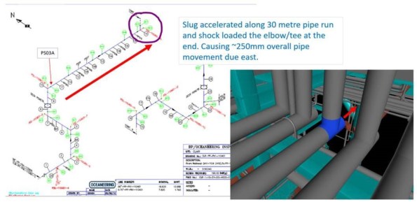
Figure 1. Inspection isometric and 3D model screenshot
The situation:
The pipe run shown in Figure 1 is a production flowline. A choke valve is used to regulate flow and will normally be placed in close proximity to the Christmas tree. On the Clair Phase 1 platform it is at the downstream end of the flowline closer to the production equipment.
When a well is shutdown, gate valves in the Christmas Tree and the choke valve are closed. This traps an inventory of fluid in the production flowline which separates into two separate phases with the gas rising to the top. Similarly, in the riser below the Christmas tree the fluid separates, leaving a gas plug below the Christmas Tree at pressure at a higher pressure, a liquid slug above it and a gas plug above that. On start up the Gate valves are opened, and flow is regulated by the choke valve.
On the system in question the gate valves stick then rapidly open fully, allowing the riser gas plug to accelerate the liquid slug through the flowline. There is a straight, horizontal 30m section of flowline (red arrow in Figure 1), along which the slug can build momentum and subsequently hits the 90-degree bend. This has been found to move the pipe 250mm axially with a potential force of 20 tonnes. If the gate valves didn’t stick and could be opened gradually the effect would be reduced, unfortunately replacing these is not an option.
Now, my first thought was to move the choke and reduce the inventory of fluid between it and the gate valve or replace the gate valve. These options have been rejected in large due to the fact they cannot be completed with the well online and producing oil. This follows, what I see as, the underpinning principle in the oil industry in all projects and decisions: “The Oil Must Flow!”
There is also the issue of the flowline being formed of welded joints throughout its length and so would require hot work to create flanged connections for a new valve. This would need a whole platform production outage to minimise the risk from hot work. The other flowlines on investigation also show movement and so any solution needs to reduce the risk for all.

Figure 2. Design for individual pipe supports and required bracing
The solution proposed is to provide bracing to each vertical pipe length, bolted to the web the I beam supporting the horizontal pipe, with an I beam bolted to other side of the web. Additional bracing with then transfer the force through to the main steel work above the pipelines. This set up will provide axial bracing for the flowlines restraining the resultant movement. This was deemed accessible after stress analysis of the pipes showed no areas of concern. Not necessarily elegant but does enable the system to cope with the effects of poor design.

Figure 3. Vertical braces to main steelwork to transfer load
The surprising thing is that this design flaw has appeared on two platforms in the BP North Sea portfolio.

Ben, what investigations have been completed to understand why the valve is sticking? Is it anything to do with the Joule Thompson effect, or simply mechanical issues with the actuators? Or is it something else entirely?
Hi Jim, The original investigation which was carried out came to the conclusion that the valve sticks due to wear and the large differential pressure. There were no recommendations made concerning the actuators and no icing, however, there does not seem to have been any in depth focus on the valve. The gate valve is a “wing valve” on the Christmas Tree and as such comes under a different section of the business. As it does work the focus was on solutions which minimise production losses, also getting the valve changed through the other part pf the business would most likely have a longer lead time and extend the duration the asset was carrying the risk.
The valve is already designed to open in 6 secs, so will likely open in between 4 and 6. This remains quite fast given the location and pressure head within the well. If the valve were to be replaced it would likely need to be re-spec’d as well in order to increase this time. The other pipelines which show signs of slugging events having occurred do not have the same valve issue. So the sticking is likely increasing the max size of the slugging event which was why it was identified.
Sounds like a bit of a quandary. Fully restraining a pipe is never a good thing, has thought been given to thermal expansion when the pipe is blocked?
Are there any options to sequence valve closure or bleed gas pressure from the line?
Efforts have been taken not to fully restrain the pipe. The new supports will only brace the pipe in the direction of the slugging force (axially along the 30m horizontal). The new supports just sit against one side of the pipe allowing for thermal expansion. They will also be fitted with fretting pads to mitigate damage that could be induced by general sources of vibration, e.g. wind/wave.
On other pipes which have shown evidence of movement from slugging, the plan is to remove the double gripping u-bolts which were part of those flowlines original construction which do rigidly restrain the pipes. Any horizontal movement under these gripping u-bolts causes wear to the pipe.
These will be replaced with non-gripping u-bolts which will restrain vertical movement of the horizontal pipe but allow movement horizontally. The horizontal movement will then be mitigated by the new supports.
Having looked over the opening sequence there isn’t anything which could be changed to remove the potential for slugging. What has been done in the short term is to introduce to the start up procedure extra steps to mitigate slug generation. The flowlines are pressurised using water lowering the DP and reducing the potential force of any slug. This is a time consuming procedure as the only access points along the line is through small gauge bleed valves on pressure transmitters. This is not practical in the long term and it increases start up time and pressure on the crew.
Potetnial force of 20 tonnes? I guess we are talking 200kN? Which is not a small number for a structure to withstand so any attempt to hold that as a point load onto steelwork had better pass through the hands of the structural designer. I note a new 406x150x67 UB going in but see nothing on web stiffening at point of loading. Might be OK with the UC acting as a stiff spreader plate but surely you can design out the point load using a swept bend or internal baffling to create turbulence and self disrupt the slug, failing that whatever happened to surge valves or shock tanks? So happy this is a very fuzzy memeory!