Archive
Infrastructure Advice
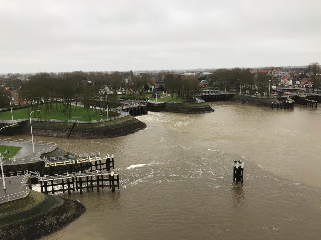
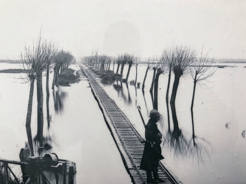
PEW are currently on a WW1 Battlefield Tour, focusing on the area around Ypres. The first stop today was to Nieuweeport, on the Belgian Coast. It was from here that the German advance through Belgium was halted through infrastructure.
The area between Nieuweeport and Ypres is known as the Polder Plain. An area of ground that sits between the sand dunes on the coast and the clay ground around Ypres. In the 17th century the land was artificially drained by the Flemish Engineer Wenceslas Coberghar to enable the land to be farmed. The result is a complex irrigation system which feeds into the River Yser.
During the initial stages of the war, with a Belgium under threat of total German control, King Albert of Belgium made the decision to inundate the Polder plain with sea water. This was done in a controlled fashion over a number of nights. Advice was given by the Belgian engineers who ran the irrigation system; they also oversaw the execution.
The result was that the Germans were halted which assisted the British in the defence of Ypres.
Location, Location, Location!
Location, Location, Location!
I am managing a project which will install additional supports to a flowline on a BP production platform which I think highlights an important factor in pipe design – location of valves.
First a quick bit of background:
Production flowlines connect the surface wellhead with the production equipment, shown in attached image. During well start-up these can suffer “slugging” incidents.
Slug flow can occur due to fluid properties and process conditions (Hydraulic slugging), the system design (Terrain Slugging) or due to a rapid change in pressure (severe slugging). This is a two-phase flow regime characterised by a liquid “slug” followed by a gas bubble (slug and bubble often described as a unit cell).
In hydraulic slugging the flow regime is constant with an associated frequency of slugs with the potential to cause fatigue failure if not correctly designed for; this is like repetitive hydraulic shock/water hammer events. Terrain slugging is a lower frequency slug flow formed by a build-up of liquid in low points of the pipeline with an associated increase in the upstream gas pressure resulting in the held-up liquid forming a slug.
A sever slugging event results from a rapid change in pressure and is the main slugging type seen by production flow lines. From the subsea well the oil and gas is brought to the production platform via a riser pipe which enters the platform through an assembly of valves known as a Christmas Tree. From there the fluid moves through a production flowline to the production equipment.
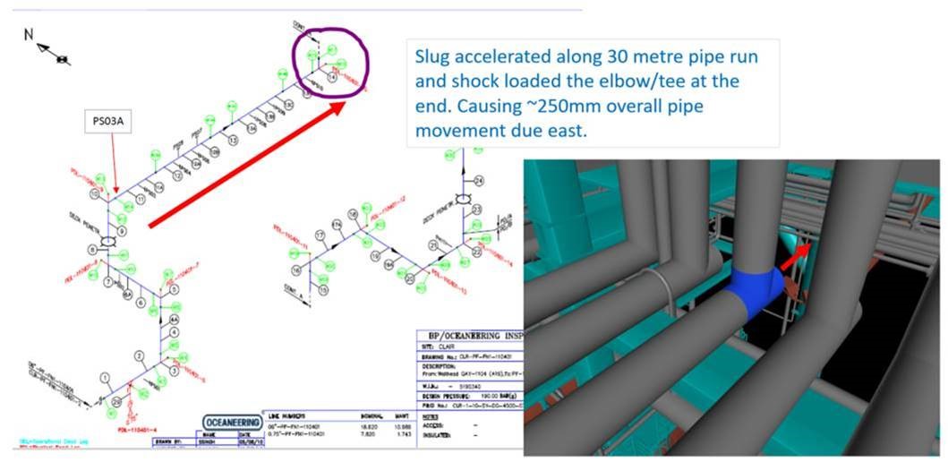
Figure 1. Inspection isometric and 3D model screenshot
The situation:
The pipe run shown in Figure 1 is a production flowline. A choke valve is used to regulate flow and will normally be placed in close proximity to the Christmas tree. On the Clair Phase 1 platform it is at the downstream end of the flowline closer to the production equipment.
When a well is shutdown, gate valves in the Christmas Tree and the choke valve are closed. This traps an inventory of fluid in the production flowline which separates into two separate phases with the gas rising to the top. Similarly, in the riser below the Christmas tree the fluid separates, leaving a gas plug below the Christmas Tree at pressure at a higher pressure, a liquid slug above it and a gas plug above that. On start up the Gate valves are opened, and flow is regulated by the choke valve.
On the system in question the gate valves stick then rapidly open fully, allowing the riser gas plug to accelerate the liquid slug through the flowline. There is a straight, horizontal 30m section of flowline (red arrow in Figure 1), along which the slug can build momentum and subsequently hits the 90-degree bend. This has been found to move the pipe 250mm axially with a potential force of 20 tonnes. If the gate valves didn’t stick and could be opened gradually the effect would be reduced, unfortunately replacing these is not an option.
Now, my first thought was to move the choke and reduce the inventory of fluid between it and the gate valve or replace the gate valve. These options have been rejected in large due to the fact they cannot be completed with the well online and producing oil. This follows, what I see as, the underpinning principle in the oil industry in all projects and decisions: “The Oil Must Flow!”
There is also the issue of the flowline being formed of welded joints throughout its length and so would require hot work to create flanged connections for a new valve. This would need a whole platform production outage to minimise the risk from hot work. The other flowlines on investigation also show movement and so any solution needs to reduce the risk for all.
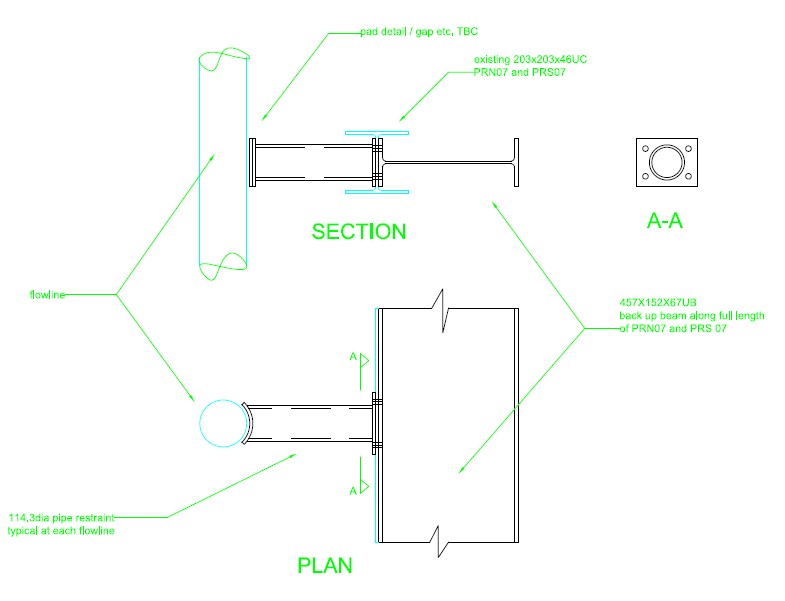
Figure 2. Design for individual pipe supports and required bracing
The solution proposed is to provide bracing to each vertical pipe length, bolted to the web the I beam supporting the horizontal pipe, with an I beam bolted to other side of the web. Additional bracing with then transfer the force through to the main steel work above the pipelines. This set up will provide axial bracing for the flowlines restraining the resultant movement. This was deemed accessible after stress analysis of the pipes showed no areas of concern. Not necessarily elegant but does enable the system to cope with the effects of poor design.
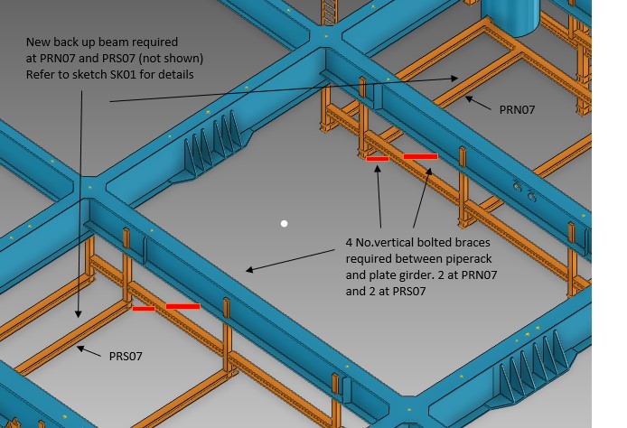
Figure 3. Vertical braces to main steelwork to transfer load
The surprising thing is that this design flaw has appeared on two platforms in the BP North Sea portfolio.
A useful reference for any Australian PET Student
Hopefully, if I’ve uploaded the document correctly the link below should be a useful reference for any PET student in Australia dealing with reinforced concrete. I wish I’d known about the reference on Phase 2 as it would have made site works so much easier. I just been shown the reference half-way through Phase 3 and wish I’d been shown it at the start of my consultant placement.
Z 06 – Reinforcement Detailing Handbook
Health warning: the link above is based on AS3600-2009 the latest version of the code is now 2018 so check and see which version is being used on your site/project and find the 2018 version if you need to.
For the civil students, it is a combination of Concise Eurocode 2, Economic Concrete Frame Elements to Eurocode 2 and the concrete equivalent of the blue book. It also contains detailed guidance on how concrete and reinforcement drawings are drawn to Australian standards (generally not different to UK standards but helps plug the gaps left by Phase 1).
For any E&M students, it’s a ‘concrete cheat-sheet on steriods’. Worth a check if you need to know the requirements or principles behind the reinforcement or concrete in reinforced concrete. The book also contains lots of look-up tables so you don’t have to calculate minimum lengths from the code clauses and explains what all the drawing symbols mean.
A question for the PEW staff – does the wing have a list of useful design references? If not, it could be a useful reference for the students in Phase 2 and 3 (and beyond) particularly if the list maps the UK standards to the Australian and American equivalents. Any thoughts?
Prestress Losses and Excel
Apologies, but this blog is aimed at the Civils as a recap of Phase 1. My design team are now well into the detailed design stage of the three bridge widening packages I am working on.
One of the areas I have been focused on has been to check the prestressed Super-T Girders (pre-tensioned) that are being used on each bridge structure at the point of prestress transfer. So I thought I’d recap anyone interested in prestress losses for post tensioned members and thought I’d share the spreadsheet I’ve been working on for the last couple of weeks.
The Super-T’s are ‘off the shelf’ sections that have seen popular use across the state of Victoria for the last couple of decades. However, the lengths of these vary and as such, the choice of Super-T profile will be dependent on this, amongst other factors – generally the longer the span, the greater the moments etc.
My main role has been to check the concrete strengths (compressive and tensile) at the point of transfer. The precast Super-T’s are to be ‘steam’ cured to allow the prestress transfer to the concrete to occur at 24 hours.
Considering there are 3 bridge structures with a total of 12 spans ranging from 24m to 39m and proposed Super-T depths of 1200mm and 1500mm, I decided to create a spreadsheet to speed up the process – I initially started by hand, which was taking a long time and was very environmentally unfriendly!
I started by going back to lecture notes/slides from Phase 1 and familiarised myself with Bungey, Mosley and Hulse (Reinforced Concrete Design to EC2); noting I am working to Australian Standards (AS5100.2 and AS5100.5 – so this could be of use to Mark) however it was useful for the analysis, such stress calculations:
![]()
For a pre-tensioned member such as this, prestress losses include: Elastic shortening of the concrete, creep and shrinkage of the concrete and relaxation of the steel.
The losses I was concerned with initially was the immediate losses at transfer. For pre-tensioned concrete, when the tendons are cut, and the prestress force is transferred to the member, the concrete undergoes immediate shortening due to prestress. The tendon also shortens by the same amount, which leads to loss in prestress.
Elastic shortening is dependent on the modular ratio and average stress in the concrete at the level of the tendons. Given there are 40+ strands at various distances above and below the centroid of the member (see section), I have taken a simplified approach, which is to use the centroid of the strands; this changes along the beam where some strands are de-bonded towards the end of the beam.


In short, the elastic shortening is quantified by the drop in prestress in a tendon due to the strain in the tendon. By calculating the strain in the tendon, it is possible to know the strain in the concrete as they are assumed the same; i.e. the concrete strain is the same as the steel strain. By knowing the strain in the concrete and the elastic modulus (which is taken at 24 hours), we can calculate the stress in the concrete – this is also true for the top and bottom of the beam.
Once the stress in the concrete at the top and bottom of the beam is known, we can check that compressive and tensile stresses are not exceeded at a concrete age of 24 hours. And by knowing the stress in the concrete at the centroid of the tendons, we can calculate the prestress loss. However, this is an iterative process, as the prestress originally used in the calculation (i.e. 100% of the jacking force) was incorrect as there was a loss – this is where excel makes it much quicker!!! (I have used the goal seeking function to do this).
In addition to this, I have included longer term effects by calculating creep and shrinkage losses, thermal effects (which includes a very funky polynomial graph to the 5th power – this took a day in itself to set up), and residual creep losses.
Anyway, I thought I’d share the spreadsheet (that is set up for the 1200mm deep Super-T’s in these pictures) for anyone interested or in case anyone finds themselves needing it – noting this is set up to Australian Standards and not EC.


The spreadsheet explains the critical points of the beam to check – as a note, I have set the critical points for one half of the beam only as beams are symmetrical. If anyone has any questions, feel free to ask!
I had trouble uploading the spreadsheet so there are some pictures below of the input data and summary pages or you can access via the following dropbox link: https://www.dropbox.com/s/uh68yephxky4rk3/Super%20T%20Prestress%20Losses%2C%20Thermal%20Effects%2C%20Creep%20and%20Shrinkage.xlsm?dl=0
On another note, my excel skills have improved drastically – turns out it is far more powerful than just creating nominal roles …


NORM
Long-lived radioactive elements such as uranium, thorium and potassium and any of their decay products, such as radium and radon are examples of NORM – Naturally Occurring Radioactive Materials.
Recently I had a project which was delayed when when an area of an asset was closed due to unacceptable levels of radiation. This was due to a build up of scale which contained Radium. This had to be cleared prior to the area being accessible for completion of the project.
NORM presents a problem for a number of different industries shown in the list below from the World Nuclear Association.
- The coal industry (mining and combustion)
- The oil and gas industry (production)
- Metal mining and smelting
- Mineral sands (rare earth minerals, titanium and zirconium).
- Fertiliser (phosphate) industry
- Building industry
- Recycling
It occurred to me that this should be a consideration for any reconnaissance when evaluating industrial sites during or post conflicts. Installations should maintain procedures and monitoring which could be identified.
Has anyone else had issues with NORM during their attachments?
Friction connection?
This is interesting. I’m checking a design for a temporary concrete retaining wall. The wall itself is simple enough but the connection is something I haven’t come across.
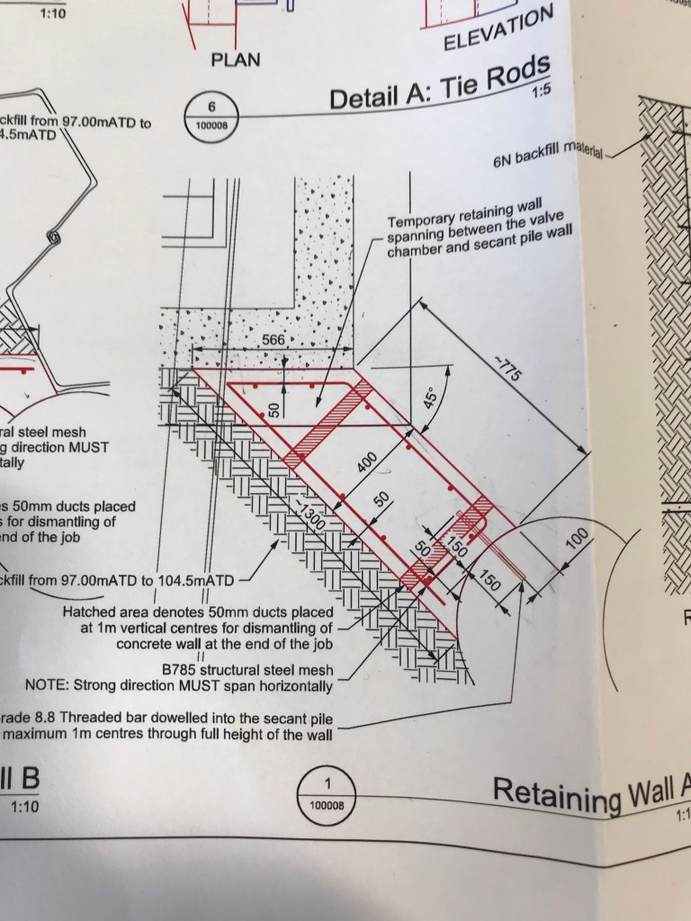
The wall is being held in place with a threaded bar on the right and “friction with the existing wall” on the left. So the designer has said that the angle between the retaining wall and existing wall is enough to restrain the wall. The engineer model I created for it looks like this
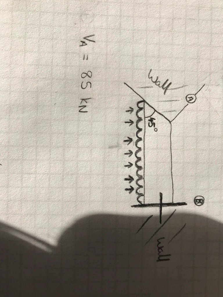
I think as the there is no bond between the two walls that friction alone cannot restrain the 86 kN. I think I should calculate the amount of load that can be taken by the friction (F= u N) away from that end reaction and then treat the B reaction as a reduced cantilever ie increase the shear load in the threaded bar.
Happy for anyone to tell me I’m wrong.
Non-standard Electrical Supplies
I stumbled across an interesting building last week whilst out on a Fire Compliance Survey. Within the Devonport Dockyard, Babcock have a building called the Central Frequency Changing Station (CFCS). This feature is responsible to the provision of “Shore Power” electrical supplies across the dockyard and HMS Drake Naval Base.
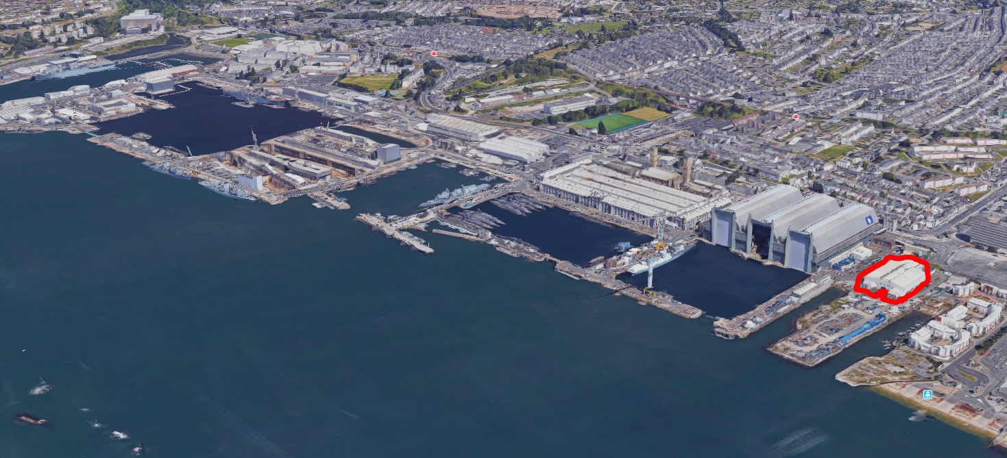
Devonport Dockyard showing CFCS building
Once large ships and subs are docked, there is obviously still a requirement to run auxiliary systems such as HVAC, lighting, battery charging, communications centre, computers and navigation systems. The vessels can provide their own power with their on-board diesel generators, but this results in noise, vibration and emissions as well as driving up running hours and using up vast amounts of fuel. The obvious choice is to just “plug them in” to a “shore supply”.
There is one slight issue; as the vessels make their way from international port to international port; the local power grid supplies can, and do, vary. Most vessels are designed to receive a shore supply of 6600 Volts at a frequency of 60 Hz. “Oh no” I hear the E&Ms cry! Here in the UK we use 50 Hz and generally a HV supply of 11 kV.

World wide electrical frequency standardisation 50 vs 60 Hz
So how do we get around this? Each “Shore Supply” is converted to 6.6kV at 60 Hz by motor-generator units. The CFCS building houses 12 x 10 MVA “common-shaft” synchronous-motor frequency converters.
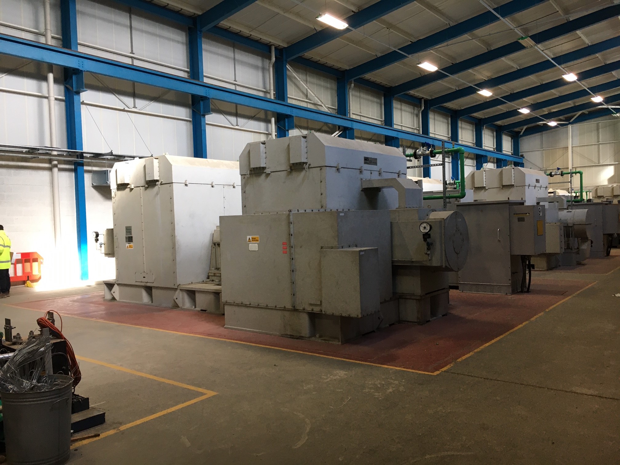
Rotary “Common-shaft” Frequency Converter Units
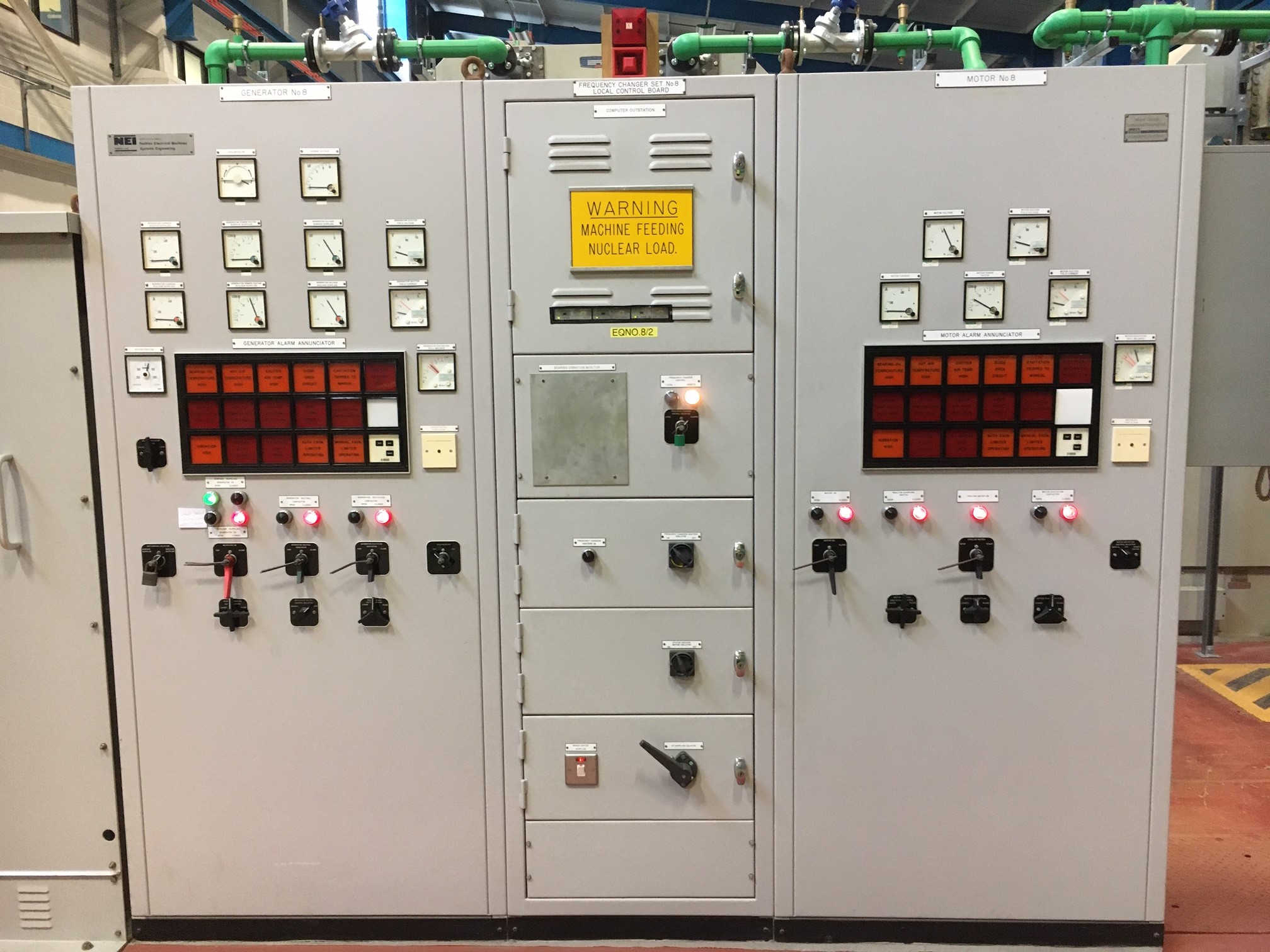
Frequency Converter Front Panel
Each of the sets uses a 50 Hz supply to produce an output of 60 Hz through the use of a “common-shaft” converter. Frequency conversion is achieved by winding the motor with a different number of electrical poles than the generator. A 10-pole motor and 12-pole generator are used to provide the conversion from 50-60 Hz . Using a synchronous drive motor ensures the frequency is maintained at a constant level to ensure power quality. Rotary units are selected as they are more reliable than solid state converters which create a synthesised output voltage and are prone to unwanted harmonics.
The sets give off a lot of heat which means the building requires heavy ventilation and the units themselves are served by a water cooling system which can be seen by the pumps and green pipework shown dotted around the installation.

Circulation pumps for Frequency Converter cooling system
The 60 Hz supplies are then distributed via what I was told is the largest switch-room in Europe (citation needed!).
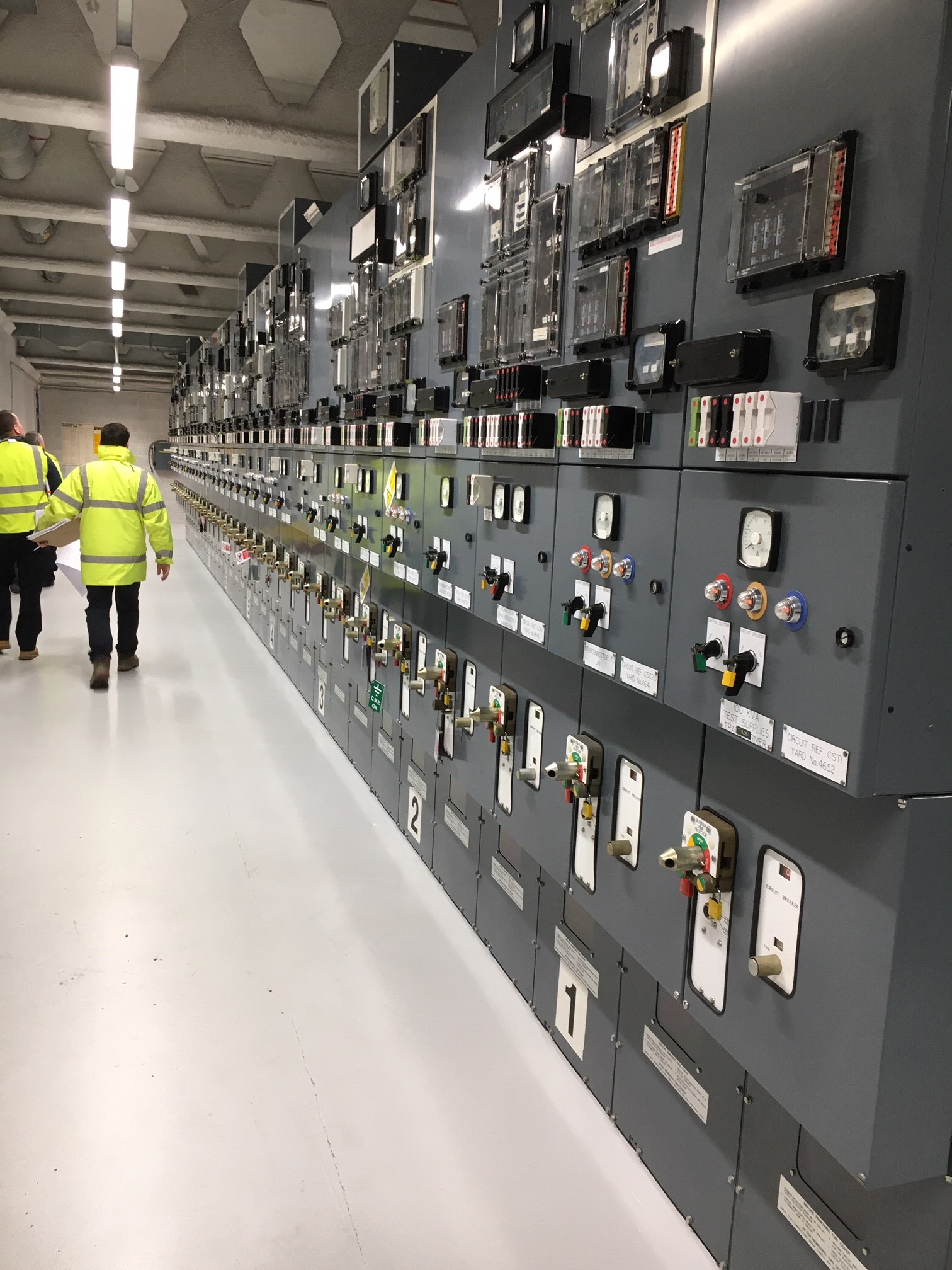
Dockyard Shore-to-Ship Electrical Supply Control Room
Just as a side note – A higher frequency is the preferred choice for many applications as motors and generators which run faster, have a better power to weight/size ratio and therefore take up less space. The same reason is why the aviation industry uses 400 Hz – smaller, lighter components for the same shaft power output.
What other locations or facilities are people aware of that have different supply requirements? Have you seen any “funnies” on your travels so far?
The Great Escape
I’ve been supervising a fun little job on my project in the City and remembering Ash’s CI’s Paper presentation on tunnelling I thought I would share.
The challenge is to connect the new building into the existing sewer which lies 10m beneath the junction of Bishopsgate and Leadenhall Street – two of the busiest roads in the City. The process will be to break through the secant piled basement box and tunnel under the road to find the sewer under the street.
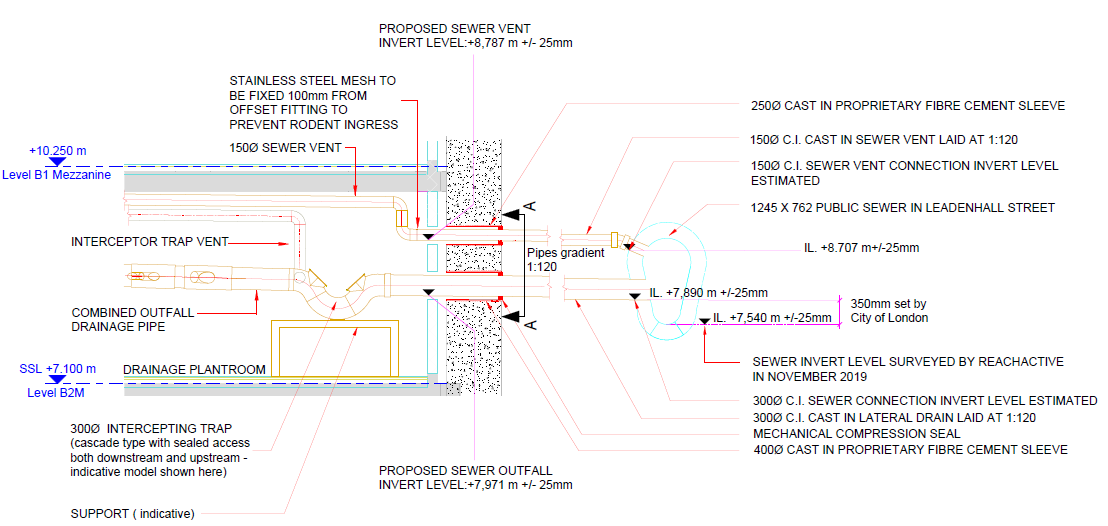
Cross section through proposed connection
There is however no fancy machine option for this job and the solution will be good old fashioned timber heading or mining. This is pretty much the exact process seen in The Great Escape and, judging by some of the characters who do this work, I don’t think H&S attitudes have advanced much since then (see video link at the bottom).
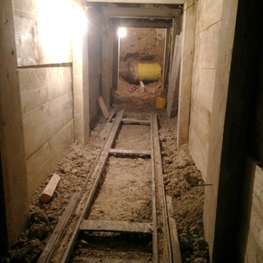
Example timber heading
Timber headings like this one are surprisingly common still, especially in London, so we had a few examples to follow as well as the British Tunnel Society guide “Traditional Timbering in Soft Ground Tunnelling”. What makes our tunnel a bit special is the need to dig through River Terrace deposits rather than the preferred London Clay. The BTS guide makes it very clear that this is seriously sketchy and lays out a load of extra considerations but, in short, it can be done.
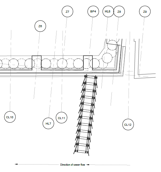
Dig line from the basement box to the sewer
The general method of timber tunnelling is portrayed quite well in this cartoon though our tunnel will need to adopt the Newcastle tucking frame method for use specifically in granular soils.
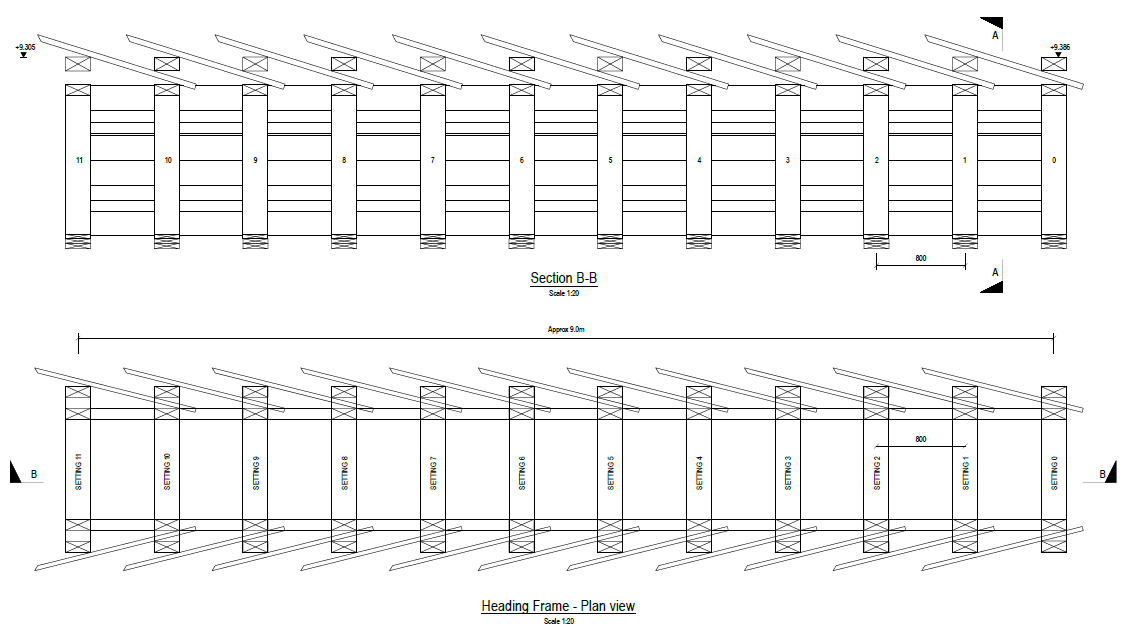
Newcastle tucking frame heading design
For the unmissable, immersive experience check out this time-lapse video of some nutters digging one of these tunnels. It needs sound but is well worth it.
Next year’s PCM exam?…
In Melbourne there is currently a situation straight out of Greg Tripp’s PCM exam…
Project Setting:
The West Gate Tunnel Project is an A$6.7 Bn portfolio of projects to improve East-West journeys through Melbourne with a target completion date of 2022. The project is funded by the Victorian Government who has employed a private company (Transurban) to deliver the project. In the project setting Transurban is acting as the Client. The designers are an Aurecon Jacobs JV (AJJV) and the contractor is a CPB and John Holland JV (CPBJH). AECOM and SMEC have formed a JV (ASJV) to fulfill the Proof Engineering role.
The problem:
The tunnel alignment runs through a site that was previously used as the Country Fire Authority’s Fiskville training college. The site was known to contain soil contaminated by PFAS (Per/Poly-Fluoroalkyl Substances) which was used in legacy firefighting foam. The college closed in 2015 partly due to the PFAS contamination risk.
I understand at the time of signing the contract, the Client and Contractor JV were aware of the presence of the PFAS. However, since signing the contract, the Australian Environment Protection (EPA) Agency has classified soil containing PFAS as contaminated material. Despite determining PFAS as contaminated waste, the EPA has not issued a classification for the waste which means it cannot be transported off-site for disposal. Consequently, the TBMs have sat at the bottom of their entry shafts for 6 months and not moved an inch and over 130 staff have been laid-off.
Although I have not seen the contract, the media is reporting that the Victorian Government’s contract with Transurban transfers the risk of soil contamination onto Transurban. As the issue has not been resolved after 6 months CPBJH has notified Transurban they wish to terminate the contract arguing a ‘Force Majeure Termination Event’ (an event beyond the control of both parties has occurred preventing a party from fulfilling their obligations). Despite the commercial dispute works continue on-site and in the design offices.
The Stand-Off:
CPBJH’s intention is to negotiate a new contract for the completion of the remaining works.
Transurban disputes CPBJH’s notification and is arguing the contract remains valid.
The government is arguing that Transurban and CPBJH must resolve the dispute and the project must still be delivered on schedule.
The workers union is putting a lot of pressure on the Victorian Labour Government due to the number of workers affected by the delayed works.
What do you think?
- Who owns the contamination risk?
- Was the contamination foreseeable to the Contractors?
- Does CPBJH have a right to claim a Force Majeure Termination Event?
- Who should bear the cost of building a new contaminated waste disposal facility for the PFAS contaminated waste material?
- Should the EPA bear more responsibility for the impact on-site?
- How involved in the resolution should the Victorian Government be in the resolution?
- Where do the AJJV and ASJV stand if they conduct design and review work after CPBJH has notified Transurban of their intent to terminate the contract?
- Dan you worked on this project. Any inside thoughts?
Government Warned 6 Months Ago
West Gate Tunnel Builders Seek to Terminate
