Archive
Your thoughts on blast vibrations.
I know I said I wouldn’t blog again but this is pretty interesting. I am looking at bidding for a contract for an 8 level basement in argillite rock in the centre of Brisbane. This will be the deepest basement ever built in Brisbane is quite ambitious.
I have two problems:
- The site is surrounded by heritage structures and the Riverside Expressway which have vibration limits of 5 mm/s.

Aerial View of Queens Wharf Development
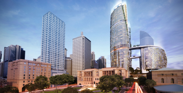 The shiny structure is Queen’s Wharf – you can see why blasting rock may be an issue.
2. I did an excavatability assessment and nearly the whole thing needs blasting.
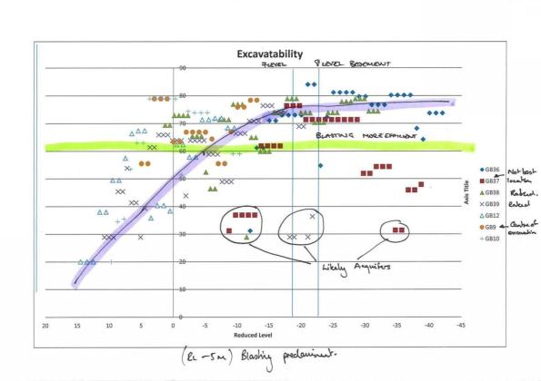
Excavatability Assessement (GSI vertical axis and Reduced Level horizontal axis)

Site map and boreholes GB27-GB35 are missing!
The less permissable vibration the greater the cost (see below). The arguments for the 5mm/s limit come from a german code (the most stringent). I need to produce a paper to argue with ARUP that this vibration limit can be increased. There is about $3 M AUD in savings if I can increase or mitigate the vibrations. Any thoughts?

Some useful background reading.
200281_ Selection of Blasting Limits for Quarries and Civil and Construction
Site Recce and My Last Blog
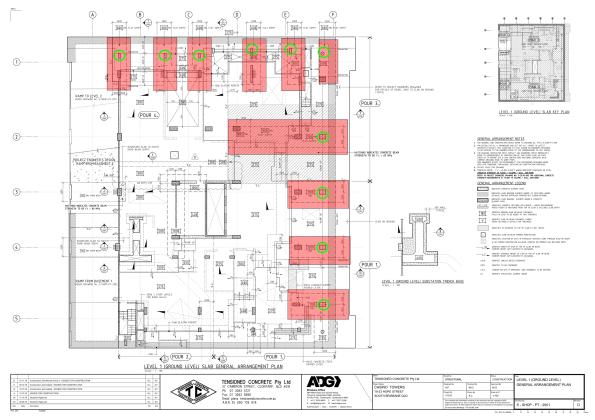
I was recently involved in submitting a tender for the construction of for a proposed development that had 3 x 30 storey towers and a common 3 level basement in Brisbane.
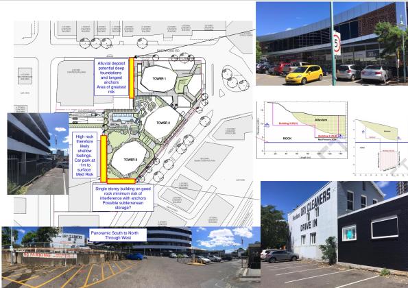
I was asked to look at where there were likely to be clashes of ground anchors and neighbouring structures. The image above is what I prepared to brief the bosses and contains a section through the development to show what the rock horizon is.
After conducting a desk top study I had to recce the site and determine what the likely foundations were and whether they could impact upon the ground anchors that would temporarily retain the basement. From the desk top study I has a good idea the ground profile but no idea of what the foundations of the neighbouring structures were. As the site was only 30 mins away I decided to take a trip out to visit.
As an interesting aside – the dry cleaners photographed above has been leaching chlorinated solvents into the groundwater that has now contaminated the whole site and meant that we have to vapour proof the entire basement because the of these volatile organic chlorinated compounds (VOCCs) into the groundwater.
We had previously looked at a soldier pile and panel solution to retain the basement in areas of good rock and then a water tight wall. This pile and panel solution would now need a bentonite lining and then vapour proof barrier. Attached is a sketch of the design I compiled along with the sub-contractor and environmental consultant. This is not easy to construct and is going to be very expensive as it needs to cover the whole basement. Given the new information the client has withdrawn the tender and is looking at possibly doing away with the basement altogether.
Scan-to-Me from 10 4 31 1 2017-04-04 074557
The end is very much nigh. The attachment to the Multiplex Queensland Head Office has been more beneficial than I initially believed. I have gained significant technical experience from a first class structural engineer but also a vast amount of contractual experience. I have had the opportunity to lead on geotechnical design and hopefully has provided me with some useful case studies for CPR.
In other news the family enjoyed one last holiday in the sun. It was very much needed after the thesis! Mark – bring on the photos of Namibia!
![IMG_6964[1].JPG](https://pewpetblog.com/wp-content/uploads/2017/04/img_69641.jpg?w=595)
Sam and Izzy (with friends) enjoying Fiji
That’s not a crack this is a crack!
![IMG_6764[1]](https://pewpetblog.com/wp-content/uploads/2017/03/img_67641.jpg?w=595)
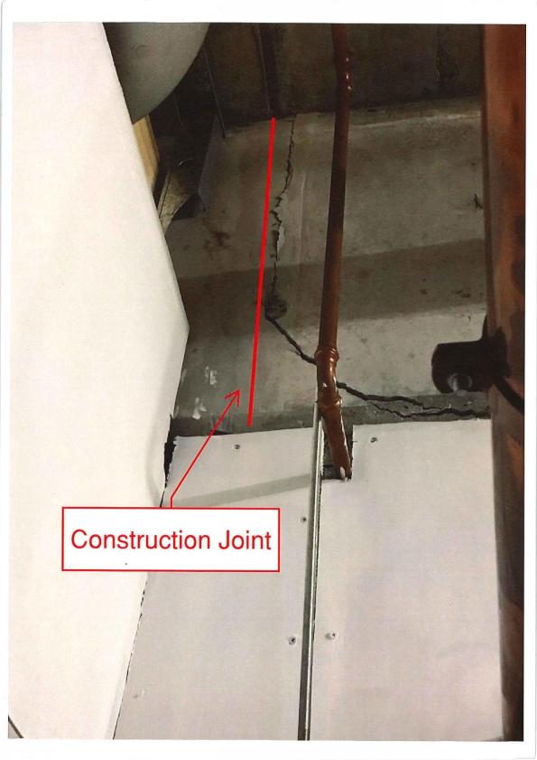
I thought BCT had problems! My boss and I were called in to investigate a crack at the Fortitude Valley Site. They are having some problems with their consultants. They have recently installed a crane and they thought it might have caused this cracking. It hadn’t what had caused the cracking was a construction joint that hadn’t been correctly designed. The connection had failed and there was evidence of shear cracks across the slab where the load had tried to redistribute. There are 20 floors of load on this slab!

Johnny Age 5 sketch
![IMG_6774[1].JPG](https://pewpetblog.com/wp-content/uploads/2017/03/img_67741.jpg?w=595)
This shear crack doesn’t look much but it shows that the transfer slab is in distress. Note the angle of the crack. Construction joint is above pipe
- Lack of specific construction joint for the transfer slab.
- The key of the construction joint was too close to the bottom of the slab. All of the vertical load was being transferred into the key detail at the bottom of the slab that then sheared off.
- In sufficient shear reinforcement.
- Construction joint located near an area of high shear.
- lack of oversight by structural engineers in Melbourne.
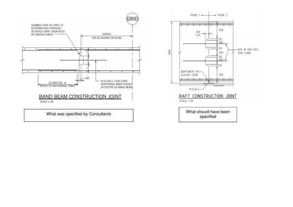
The Bad (what was detailed left) and good (detail from another site right). Note the key detail on the right and roughed finish

The offending construction joint before the pour. Note – no shear reinforcement and the key is close to the bottom of transfer slab!
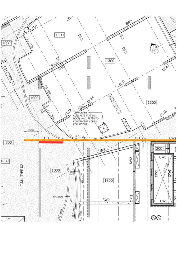
Plan view of the site (red is area of cracking). CC2A are columns that terminate at the transfer slab.
They said I was mad to build a castle in a swamp!
Monty python-Holy Grail
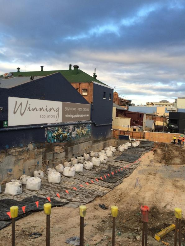
In my last blog I mentioned building a basement in a swamp. The tender is on a brown field along a tributary of the Brisbane river known as Breakfast Creek. The site that has recently been cleared (ish). On my recce I began to feel a sinking sensation in the pit of my stomach. The ground here is truly awful but, the client is adamant that he wants his basement.


Design. The structure is a 6 storey Mercedes show room/car museum with a single storey basement. The client’s design calls for a temporary retaining wall and then a concrete bath tub to keep it watertight constructed on the inside temp retaining wall. The structure itself will be supported by pile footings. It was originally tendered as a Traditional construct only package but, due to the risks is now being let as a Design and Build.

Boundary. Argillite bedrock between -7 and -31 m. Level of Bedrock varies across the site from -7 m in West to -31 m in the East.
Properties. Very Soft Alluvial Clay φ’ = 25 ° and c’ = 0 until Hard Argillite Rock.
Groundwater. Tidal range of RL +0 to 2 m (+3.5 m flood level)
Contamination. You guessed it ASS is back. With some potential hydrocarbon contamination.
Issues. The client wants this basement even if it costs him $5 Million.
- It is a swamp! It is possible to cantilever 5 m in this rubbish but the toe stability is the problem. The solution at the moment for sheet and contiguos piles is to have every 3rd pile down to the base rock which can be up to 31 m.
- The pile loads for earthquake loading are massive. Brisbane isn’t in a seismic zone but like all building it needs to be design to withstand a basic seismic. The problem is that because the neighbouring soil isn’t worth a damn the tension loads carried by the pile foundations are over and above what you would expect of a 6 storey building.
- Hydrostatic slab. Given the high ground water level, the basement needs to be designed for a hydrostatic slab. The original design calls for beams to carry this load but, this will be a nighmare for something that cannot achieve a batter of 1:2.
- Heritage structure. An existing heritage bridge abutment (not in use) is on the perimeter of the site and it cannot be damaged, despite the fact that it has failed.
- Existing retaining walls. The client also wants to keep any existing retaining wall structures that have been left in place. Unfortunately, the existing retaining walls from the previous structure show signs of distress. It appears that their is disproportionate settlement in at least one part of the retaining wall. To make matters worse there are no as-builts of the retaining wall structures.
Upside – The hotel where I took this photo does massive steaks and great red wine – so that’s how I spent the afternoon. If all recces were this good
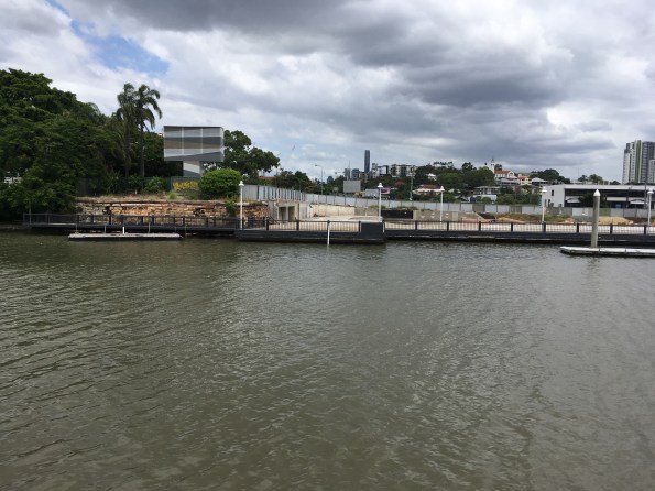
View South from opposite bank (bar). Failed heritage abutment on left. (Note high tide)
Rock blasting in the middle of the city!
Blasting next to a heritage bulding in Fortitude Valley, Brisbane City
So I am currently assessing how to build a 4 m basement car park in a swamp with a CBR of 1.5. I could go into the details of that but, while researching my thesis I came across these videos of blasting in two of my case studies Fortitude Valley and 300 George Street which are far more interesting. How do you get away with blasting very hard rock in the middle of a city? With a lot of careful planning. Note the mattresses to prevent fly rock and the drilling before hand in the 300G video not just for placing the explosives but to localise the effect of the shockwave

Details of the blast
Efficient Detailing of PT
My boss has buggered off to Melbourne for a couple of days and so I am having to seveerly raise my game.
I am looking at detailing a slab and found this usefule- please see attached link on guidance on efficient PT design. PT Detailing
Australian Structures Codes Cheat Guide
For those that are struggling with the Oz codes for detailing reinforcement or are shortly to deploy – I was struggling with lateral reinforcement for a prestressed bar to tie in a crane. I found this excellent presentation. It has certainly helped jog my memory.
Playing the blame game
My old site BCT – just seems to be the baddie in a 1980s B movie – it just won’t die. Every week brings a new issue that needs rectification. Multiplex are expecting to make a $20 Million loss on the project.
I am spending a lot of time conducting what I call ‘Post Mortems’ on projects. Each one could be a TMR by itself and can be depressing/interesting depending on how morbid your curiosity is. There are a lot of firings going on and these Post Mortems are make or break for some people. My boss described it thus – we don’t fire them ourselves we just put the ammunition in the gun. Monday saw an interview without coffee for the main players in the BCT project team. Why is your project already $1.5 M over budget in reo and you have only just come out of the ground? Below is an email of my assessment of the reo overrun sent to my oss :
The facts of the situation are these:
- Projected versus Actual. The greatest increase in reinforcement has occurred at Level One with approximately 6.5 times the reinforcement projected( 107 T against projected 16.2 T). The majority of this reinforcement is in the transfer beams on Level One (84 T). This leaves approximately 23 T of reinforcement in the remainder of the Level One slab (not including mezzanine).
- The transfer beams were added due to issues with the basement retention system. The original design called for pad footings close to the secant pile wall. However, because the secant pile wall was not deep enough in the North and East of the site, there was concern that the footings close to the wall would undermine the bottom of the wall. The decision was made early to remove the pad footings rather than issue the piling contractor with a variation. Subsequent consequence analysis seems to have been focussed on the geometrics and car park spaces. There appears to have been no formal consideration of the cost impact of the additional transfer beams. As a rule of thumb, one transfer beam costs approximately $35,000. The decision to remove the columns in the basement and use transfer beams resulted in an extra 10 transfer beams (approximately $350,000).
- Contract Award. There are no transfer beams included on the Level One sketch in the Post Tension tender documentation. While the transfer beams are shown in the capping beam documentation in S-CD-09-001 Retention Wall and Capping beam Plan, this information was not transferred to the Level One drawings. There appears to have been no tracking of the transfer beams on a design register and it does not appear to have been communicated to the sub-contractor effectively during the tender process.
Assessment. The existence of the capping beam drawings muddies the water somewhat. On one hand the sub-contractor should have been aware of the need for transfer beams from the capping beam drawings but, could argue that it was not covered by his scope because it was not on the drawings of Level One. There were several failure of process within the Multiplex team.
- Failure to communicate the addition of the transfer beams with up to date drawings prior to contract award.
- Failure to understand the second order consequences of removing the columns in the basement (Cost).
Regards,
Doug
Having thought that the PT designers had got the message about putting too much conventional reinforcement in the slabs, I received the new drawings for Podium Level 2. The previous iteration had approximately 60 T ($120,000 over budget for level 4) of reinforcement over what had been agreed in the contract. Having worked late into the night to get an answer to the project team on the savings and ground truth of their design I was disappointed to discover this iteration had shaved a meagre 15 T off that figure ($30,000 saving). Not good enough Mr Consultant show again!
In other news I have been playing around with STRAND (finite element analysis software) trying to assess the natural frequency of a 20 m span conventional reinforced concrete beam. The beam is supporting a swimming pool above the ballroom at the Jewel Hotel on the Gold Coast and there is concern that the chandeliers could swing around because of the vibrations from the pool. It’s not urgent but its fun to play with when BCT gets depressing.
How to know when you are being conned
![IMG_5441[1].JPG](https://pewpetblog.com/wp-content/uploads/2017/01/img_54411.jpg?w=595)
This should be a PT transfer slab but where is the PT?
The project is running over budget on steel reinforcement. On further inspection it appears that the post tension (PT) concrete slabs are needing double the reinforcement that they were originally budgeted for. While there has been an increase in load by 9.52% it doesn’t explain the doubling of the conventional reinforcement.
The PT contract was let as a design and build and the PT designer works for the sub-contractor. The consultants will act in the best interests of their clients which is not Multiplex but the sub-contractor. Compounding the problem is that Multiplex pay for the conventional reinforcement and the sub-contractor pays for the PT. So an unscrupulous contractor could put in more conventional reinforcement and less PT and pocket the money. In order to prevent this the contract has a limit upon the amount of conventional and a sum for the PT see below.
| Level | Area (m2) | Post-Tensioning Price
(Design, Supply & install) |
Reinforcement in PT Slab Design
(t) |
| PT slab Design | Design | $118,000.00 | |
| Level 1- Ground Floor | 1350 | $51,000.00 | 16.2 |
| Level 1 Mezzanine | 350 | $3,000.00 | 10.0 |
| Level 2 | 1535 | $55,000.00 | 39.9 |
| Level 3 | 1275 | $41,000.00 | 10.2 |
| Level 4 Transfer | 1525 | $120,000.00 | 62.7 |
| Level 5 | 725 | $20,000.00 | 5.8 |
| Level 6 | 1200 | $31,000.00 | 12.0 |
| Level 7 to 24 (18 Levels) | 21060 | $594,000.00 | 179.0 |
| Levels 25 to 29 (5 Levels) | 5850 | $161,000.00 | 55.6 |
| Level 30 | 1165 | $27,000.00 | 10.5 |
| Roof Level | 935 | $27000.00 | 12.2 |
| Total | 36,970m2 | $1,248,000.00 | 414.0t |
Having pounded my head against my desk for the last week trying to re-design the next slab (the Level 4 Transfer), and prove that they are conning us. I have come up with this simpler method to spotting you are being conned when the loads have changed.
So what do you do?
A tonne of PT steel is not the same as a tonne of conventional steel. You need to find the equivalent ratio of capacity per tonne. For 15.2 mm strand (PT) and a 16 mm bar (Conventional) this is approximately 3.5:1 at a cost of (2:1), so it is more cost effective to put in more PT if you need to increase capacity (why would the sub-contractor do this if it costs him money).
- Calculate the equivalent capacity at contract.
- Assume $5K per tonne for PT.
- Equivalent tonnage – 139.1 T
- Find increase load and percentage. – 9.52 %
- Calculate equivalent capacity needed. 152.3 T
- Find the current equivalent capacity. This is painful and involves counting bars and strands. -187.2 T.
- Calculate Difference = 34.9 T
- Calculate Cost ($2k per tonne for laying conventional reinforcement) – $70K owed by sub contractor to Multiplex.
Other stuff I have found out along the way.
The deflection they are using does not correspond to the 1/1000 (deflection to span) in the Australian codes and is currently twice what it should be. I was having a real issue bringing the deflection down – it appears they didn’t bother. The reason the best way to do this is add more PT!
The sub-contractor has increased the strength of the concrete in the transfer beams from 40 to 65 KPa. Presumably to account for the punching shear problems that I was having. However, Multiplex pay for the concrete and not the sub-contractor so this is another additional expense that Multiplex should not be liable for.
Potential talking points
- Benefits/risk of design and build
- Benefits of technical expertise in decision making
- Oversight of sub-contractors
- Ethics in the construction industry.
- The sub-contractor was repeatedly asked what were the impacts on the load changes but failed to respond.
The Most Dangerous Dam in the world

Please forgive the blatant plagiarism. I saw these article and found it very interesting. The British Base in Iraq is 2 hrs away from this Dam. While work has been done by USACE this could involve an STRE at some point in time. The real danger point is April when the Snow Melt from Turkey hits the reservoir.
I look forward to a discussion on this topic at the Southern Hemisphere PET symposium this weekend.
