Archive
Italian Bridge Collapse / Textbook Demolition Job
Thanks to lockdown in Italy only 2 people were injured when this 240m bridge collapsed at the beginning of April and, perhaps as a consequence, it has seen less media coverage than the Genoa motorway bridge collapse in 2018.
The bridge had six 40m RC arch spans between stone piers. All spans collapsed completely and at least two of the five piers were toppled in the process leading to a pretty thorough demolition job.

The state of repair of the Italian road network is clearly under considerable scrutiny and it seems likely that this bridge collapse is, at least in part, due to poor inspection and maintenance. Cracks appearing in the deck can be seen on street view and have been growing since 2011. These cracks were inspected in 2019 but no action was taken. Read more…
Gas Holder Dumpling Slip
While we’re all sitting at home I thought I’d share this nugget from 2019 that made a little comeback in a lessons learned session we had before lock down. It is also an unexpected opportunity to use the word dumpling in an engineering context.
Back in June 2019 Keltbray were contracted to demolish two old gas holders in Sydenham. These gas holders are the large expanding “city gas” storage vessels that expand upward as gas is pumped in. The gas holders in question were of the “dumpling type” with a clay mound in the base centre of the gas holder (think the bottom of a champagne bottle). The gas holder is then partially filled with water to form an effective seal against the ground as gas is pumped in (see below).

Dumpling type, two tier gas holder
As part of the dismantling sequence, the crown (lid) of the gas holder is removed, and the water and sludge is pumped out. On 12 June 2019, approximately three weeks after the pumping was completed on one of the holders, a crack through the dumpling was reported to WHP following heavy rainfall. However, the crack was first seen when the dumpling was first exposed; at the time, the crack did not alarm the site team and was considered superficial. The condition on 12 June, with the crack clearly visible, is shown below.
Virus stops play
Following on from Colin’s blog about the contractual implications of tightening restrictions on non-essential travel around the world, I thought I’d start a thread for any interesting updates on the impact to us all. (Here is the NEC article I commented about but couldn’t link).
Phase 3 for the most part are able to work from home to a greater or lesser degree but how is it affecting Phase 2? And how much work will there be for design offices, especially the temporary works houses, if on site activity dries up?
My main site in the City has closed today but the project team are still active from home and they haven’t mentioned any intention of slowing down on the planning side so all is still go here. I have heard of one or two smaller projects in our office cancelling design work but as of Monday morning we have a full workload for the whole office – we will see how long that lasts.
It has been interesting in London to note the political views on construction as ‘key workers’. The PM seems to think construction counts as worthwhile but the Mayor of London not so much. It seems agreed however that national infrastructure projects will be allowed to continue so anyone embedded in Tideway, HS2, Crossrail, Highways England, (Hinkley I imagine?) etc should have a chance to keep some money trickling in.
The Great Escape
I’ve been supervising a fun little job on my project in the City and remembering Ash’s CI’s Paper presentation on tunnelling I thought I would share.
The challenge is to connect the new building into the existing sewer which lies 10m beneath the junction of Bishopsgate and Leadenhall Street – two of the busiest roads in the City. The process will be to break through the secant piled basement box and tunnel under the road to find the sewer under the street.
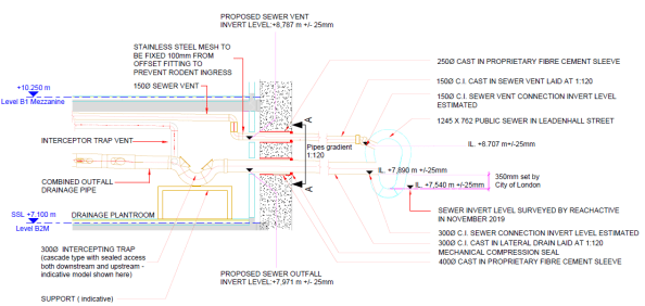
Cross section through proposed connection
There is however no fancy machine option for this job and the solution will be good old fashioned timber heading or mining. This is pretty much the exact process seen in The Great Escape and, judging by some of the characters who do this work, I don’t think H&S attitudes have advanced much since then (see video link at the bottom).

Example timber heading
Timber headings like this one are surprisingly common still, especially in London, so we had a few examples to follow as well as the British Tunnel Society guide “Traditional Timbering in Soft Ground Tunnelling”. What makes our tunnel a bit special is the need to dig through River Terrace deposits rather than the preferred London Clay. The BTS guide makes it very clear that this is seriously sketchy and lays out a load of extra considerations but, in short, it can be done.
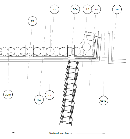
Dig line from the basement box to the sewer
The general method of timber tunnelling is portrayed quite well in this cartoon though our tunnel will need to adopt the Newcastle tucking frame method for use specifically in granular soils.

Newcastle tucking frame heading design
For the unmissable, immersive experience check out this time-lapse video of some nutters digging one of these tunnels. It needs sound but is well worth it.
Automated Construction
I stumbled across this through one of our clients and thought it was worth a comment. I’ll keep it brief and let the video do most of the explanation using nice clips the E&Ms should be able to follow.
The video shows an interesting idea for economising on the construction of simple steel frame/concrete slab type buildings. Using segmented off-site manufacturing and simple floor plate design, this method enables considerable increase in the automation of steel frame construction alongside simplifications in temporary works. Read more…
Geopolymer “Earth Friendly” Concrete
It is well known that the production of Portland cement (OPC) is highly damaging to the natural environment. It is high in embodied carbon and embodied energy and its production creates noxious waste emissions – globally, production of 1 tonne of OPC produces roughly 1 tonne of CO2. Reducing the OPC content of concrete mixes has been standard practice in construction for many years, through the use of cementitious replacement materials such as blast slag (e.g. GGBS) or fly ash (e.g. PFA) derivatives, but an Australian company is now marketing a geopolymer based concrete which contains no OPC at all.

EFC pavement
Wagner’s Earth Friendly Concrete (EFC) uses an alkali chemical powder to activate other pozzolans – cementitious content (GGBS and PFA) – to achieve the binding effect of cement. If you accept that GGBS and PFA are waste materials (which is a separate topic) then EFC can see 80-90% reductions in carbon carbon emissions when compared to a full OPC mix.
Crucially, this product is now able to match concrete in many applications and appears to be commercially viable. The fine and coarse aggregate content remains the same in terms of performance it shows:
- 30% higher flexural strength
- Very low heat of reaction
- Very low shrinkage
- High sulphate resistance
- High chloride ion ingress resistance
- High acid resistance
There are a number of case studies available (wagner.com.au) which show good performance in pre-casting and pavements in particular (including airports) with an interesting foray into sewer tunnel lining. The low reaction heat, leading to low shrinkage, is an ideal characteristic for pavements (especially I imagine in Oz where curing must be tricky in the heat?) and the high resistance to chemical attack makes it a good choice for sewers or other corrosive environments. It even has a clean white finish.

EFC precast
There certainly seems potential for use in the UK in mass concrete applications at least e.g. piling and ground bearing slabs, but I haven’t seen much evidence yet of it’s use for in-situ superstructure pours. I imagine this is a result of the low reaction heat leading to longer curing times (or vice versa at the chemical level). In a concrete frame longer curing means longer shuttering, more back-propping and slower jumps between floors – i.e. it means money – but this doesn’t apply so strongly to unpropped steel decking (composite) slabs so perhaps there is potential there too.
Has anyone seen this in use yet, especially you guys Down Under?
The return of the most expensive cube of grout
Refresher
In my earlier blog on the most expensive cubic metre of grout ever poured I ended with a hope… and a contingency.

Taking core samples from suspect grout
The hope was to take core samples from the suspect grout on the chance that the in-situ strength was higher than the cube test results which had returned compressive strengths of <40MPa after 14 days (less than half the forecast strength at this age). The design consultants had worked around the clock (literally – Robert Bird Group enlisted one of their New Zealand based engineers to work the opposite hours to the UK team) to prove the scheme with a minimum grout strength of 50MPa.
Core Samples
100mm samples were taken where we could get at the face of the grout and clearly showed the separation that we feared.


As you can see in the photos above the grout has separated and the fine aggregates (<2mm sand) have settled to the bottom. The smooth grey upper section contains the majority of the cementitious content and the chalky white crust on top is the synthetic polymer additives. The granular layer was so weak several of the samples sheared in half during extraction revealing the cross-section above.
Testing
The specimens were sent for testing (which by the way takes a lot longer than cube testing due to the time required to prepare and cap the samples) and strength results were issued. We asked for testing of the lower sections of the specimens as this is where the bearing surface is and where we suspected the lowest results.
For the two samples in the left hand photo we received cube equivalent compressive strength results of 17 and 15.2 MPa. On one slightly longer sample we were able to test both the bottom granular section and the upper smooth section. This test returned 37.3MPa in the aggregate and 70.6MPa in the cement matrix. This again supported the theory of complete segregation due to over-watering of the mix.
For anyone coming across a similar situation I have uploaded a document summarising viable In Situ Testing Techniques.
Conclusion
Instruction was issued that all affected grout was to be removed by hydro-demolition and replaced with only a month long window in order to avoid knock-on critical path delays to the project as a whole – a certain contender for the title of world’s most expensive grout.
The most expensive cubic metre of grout?
The Plan
The casting of the column bases into the pile heads is one of the key early stages in my project. To (try to) ensure the quality of this operation a carefully staged process was developed with hold points and hand over inspections involving the concrete and steel sub-contractors, the principle contractor and the designer.
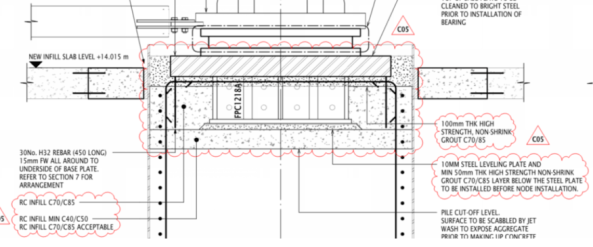
Design build up beneath the base plate within the pile casing
To leave space for the steel shear keys beneath the base plates the pile concrete cut-off level was left short of the top of the casing. The process for installing the base plates became a 6 stage operation as follows:
- Prepare the pile head as handed over by scabbling the surface and extending the rebar cage where required. Pour C70/85 concrete to achieve desired pile level, ~50mm below the bottom of the shear key.
- Install a 10mm steel levelling plate.
- Grout beneath the levelling plate using a high strength (100MPa) ‘non-shrink’ grout.
- Install the main baseplate with shear key and temporary works.
- Pour C70/85 concrete to within 100mm of the bottom of base plate.
- Pour high strength grout (100MPa) beneath the bearing surface of the base plate (max 100mm thickness) and up the sides to top of steel. Grout was specified to ensure full dispersal of the mix beneath the plate to ensure full contact with the bearing surface to satisfy the design bearing pressures from the column into the pile.
All stages had gone as planned until the final (and most important) stage.
The Execution
Unfortunately, our ‘specialist’ sub-sub-contractors clearly didn’t get the memo (or any training in mixing grout it seems). While mixing the bagged grout on site they ignored quality procedures and, following a mechanical failure with the volumetric doser, ended up adding water to the mix using the ever accurate bucket method.
The result is unlikely to surprise anyone. The grout was considerably over watered and separated in the pile casing. The cementitious content has fallen to the bottom topped by a layer of polymer additives, all submerged under 90 mm of bleed water.

Bleed water from the separated grout pour
There were immediate concerns over the strength of this grout layer and the 7-day cube result shows 39.1 MPa against a forecast compressive strength at this age of 75 MPa and a design target strength (28 day) of 85 MPa. This raises all the usual issues with failed quality tests but owing to the criticality of this bearing surface a remediation plan must be put in place within the month. Any longer than that and the designers cannot guarantee the structure for further steel erection – all of which is on the critical path.
With no float left in the programme following delays elsewhere (see my earlier blog on off-site programme) any critical delay to the programme will incur damages and costs totalling close to £1M per week.
So what are the options?
The Hope
Owing to the cause of this non-conformance (over-watering) there is no confidence that the cube result represents the in situ condition so additional testing is required. We will also take smaller core samples through the base plate’s vent holes to ascertain the profile of the grout across the bearing surface (see below).
I have uploaded an In Situ Testing Techniques guide from one of our sub-contractors for interest but for this problem we are taking simple core samples for compressive strength testing (BS EN 12504).

Core locations in failed grout layer
The hope is that a core can return a result approaching 50MPa and that the design engineer can justify this reduction in strength from the design. I suspect this is highly unlikely on both counts so what is the fall back?
The Contingency
The only fall back is to remove the grout but the access is extremely difficult. The current proposal is for hydro demolition with a curved lance to access the gap between the casing and the base plate. This is currently under review but adjusting the power of the lance should allow for the removal of the weak grout without damaging the concrete of steel beneath.
This requires considerable planning effort and time to execute. This will be followed by installing the grout again properly. And the clock is ticking before damages begin.
Lessons Identified
- A specialist is not necessarily any more competent than any one else in any given task.
- Adding water to concrete/grout, beyond mix design, is a bad idea.
- Paying to do the job right the first time is cheaper than rectifying mistakes if they happen.
- It doesn’t take long for a simple task to slip onto the critical path.
Where is the real critical path?
Being a steel framed building it won’t surprise anyone to hear that the erection of the steel frame is the current critical path activity on my site. On the face of it, all is going well; steel is flying into place and the fixing gangs are able to knock off at 2pm every Friday to head back up north for the weekend. There is no evidence of surplus steel on the site and almost everything is installed the day it arrives, leaving the lay down areas empty. All good, yes?
Unfortunately, no. While the installation can run like clockwork, the real critical path on this project is more than 200 miles away at the fabrication shops in Bury, Lancs. The volume, weight and complexity of the members being installed in the early phases of this job have the fabricators running to max capacity and, in essence, they are failing to provide steel to site quickly enough. This is resulting in considerable delays that are out of the hands of the sub-contractor’s site management teams. In an effort to understand the problems they are facing we headed north for a tour of the fab shop turning out the biggest bits for the job.
E&Ms can probably dip out of this one now with the fortune cookie take-away that the critical path isn’t always where you think it is and off-site manufacture is vital to the programme. Anyone else can carry on for a photo-heavy tour of the fab shops and what the pieces look like on site.
INTRODUCTION
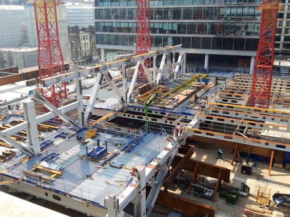
To set the scene for our visit to Bury: the early stages of this project build are 6 parallel ‘launch’ trusses which support the erection of an arch, together spanning between a pair of columns which are cast into large diameter pile heads. The trusses are two storeys tall (between level 1 and level 3) and the arches join at level 10. Each truss alone weighs around 1000 tons and is over 60m long. Pieces are manufactured then brought to site to be bolted together to form the truss.

Structural skeleton showing 6 arches through the building above the launch trusses.
When (almost) complete the launch trusses should look something like this:
Launch truss approaching completion with top chord fitted along the central section.
So how do we get to this point?


Steel arrives at the fabricator as either rolled sections or plate which are then cut to length and brought onto the shop floor for fabrication.
BASE PLATES

Work on the column bases starts with the base plate which has a shear key and reinforcing cage welded to the underside.

Plate sections are welded along their length into girder or box sections then welded to the top side of the base plate.

For simple runs semi-automated submerged arc welding can be used. This puts down more weld metal than hand-held options and is easier on the operator for numerous straight runs. Note the angles tacked onto each end of the run to allow the machine to over-run then turn around. These are ground off afterwards.

Girders are welded to the base plate before bracing and stiffeners are added. All pieces are then QA tested and dispatched to the paint shop.

A ‘standard’ column base installed with intumescent paint. The rebar on the underside laps with bars protruding from the pile cage, within the casing. The shear key is then concreted into place, pouring concrete through the mouse hole in the base plate seen in the pic.
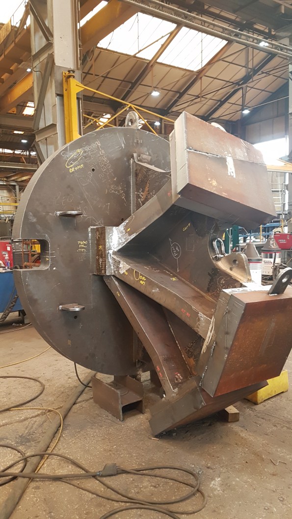
This is one of two special base plates which will support a tripod of box sections in one corner of the building. If the three column bases were ‘fingers’ the web between them is a single piece of plate steel, cut with the design curves and welded to the base plate. The column fingers are then added on either side and the caps applied. In this photo, from bottom to top, the ‘finger’ plates are 100, 150 and 180mm thick steel plate. The knuckle at the bottom is 240mm thick.
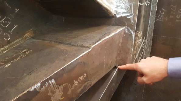
FPBW where a ‘finger’ meets the ‘knuckle’ in 150mm plate. Starting from inside the bevel (as pointed to in the pic) this weld required around 800 passes by the welder, by hand.
The complexity of some of the columns gives some explanation for the timelines required for their manufacture. This latter ‘special’ column has been in fabrication for 6 weeks and will spend at least another week being shot blasted and painted on it’s way to site. One of the columns was found during QA to have a lamination issue (layers of steel forming the plate pulling apart from each other) so had to be made again from scratch – rushed through production at best effort it has arrived on site today, 5 weeks behind its initial schedule.
COLUMNS
The columns, or column head nodes, which sit on these bases are fabricated box sections. In order to transfer load across the whole area of the capping plate, the surface needs to be exceptionally flat. The sections are fabricated and prepared then milled to achieve the desired tolerance for on-site welding to the column base plates.
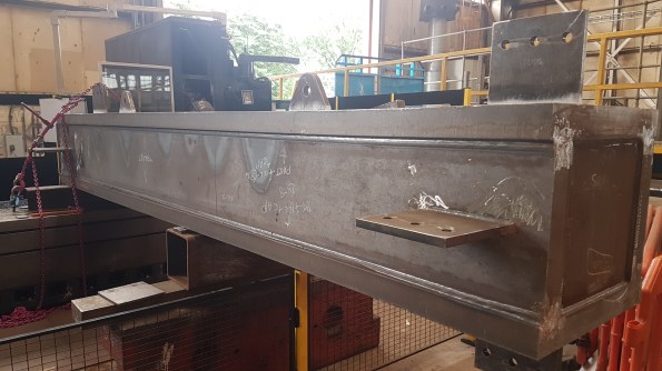
Column section after fabrication, awaiting milling.

Milled column bearing end showing the bevelled edges to allow butt welding on site.
CHORDS
The launch trusses have their principal chords at level 1 and level 3. The lower is erected first, spanning on temporary works, and the upper chord is added afterwards with the tie members. The fabrication of these complex members is time consuming and mistakes in the fabrication could set the project back weeks.

To create the truss nodes girders are combined and web stiffeners added.

The preferred weld type is full penetration butt weld (FPBW) but the steel needs to be extensively prepared to allow this process. Incoming plate needs to be bevelled to allow the full penetration of the weld. The weld metal then returns run after run to fill the bevel and create the joint (finished example on the left side of this pic). The hole in the web (called a cope hole) allows for continuity of the weld through the web; without it the right-angled joint between web and flange becomes a stress concentrator.

The finished article (almost) awaiting dispatch to the paint shop
ERECTION PROCESS
Once fitted to the pile, the standard truss columns will have bracing and a column head node either bolted or welded to them to support the lower chord of the truss.

Lateral and diagonal bracing on a column base plate

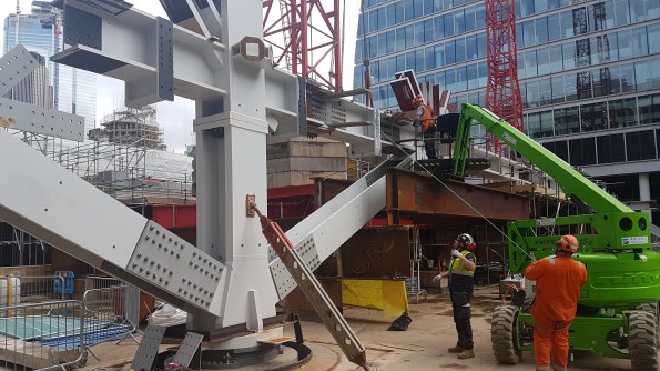
The column head node connecting, in this case, three adjacent piles. This was the first to be built to provide maximum stability to the frame while the lower launch truss chord was installed. This single lift was in excess of 20 tons, testing the limits of the tower cranes on site.

With the head node and back span (right) in place the lower truss chord was connected (left)
Making the splice connection for the first full span across the site.
Some weeks later the top chord is added with the tie members
SUMMARY
No amount of additional effort on site can speed up the construction process when the supply of finished members to site is insufficient. In this case the fabricators are working well and produce high quality products to site; unfortunately they are at max capacity and supply is still not meeting demand. With no float in the fabrication programme set backs hit hard and delays are felt to their fullest with the repercussions being felt on site.
For my part, I would advise anyone to get out and see their off-site processes (whatever they may be) whenever they can. Not only does it humanise the process, it is a vital part of construction that should be fully understood throughout the supply chain.
Steel Fibre Lightweight Reinforced Concrete
First patented in 1874 and used extensively for bomb damage repair to airfields in WW2, SFRC is a well established construction material with a number of potential benefits, especially when used in situ to form composite slabs on profiled steel decking.

Steel fibres are graded I – V according to BS EN 14889-1
Steel fibres are often used to replace the steel mesh or fabric reinforcement in slabs. As well as composite slabs, they are used extensively in ground bearing slabs and pile-supported floors and can replace much, if not all, of the traditional welded reinforcement.
By mixing steel fibres into ready mix concrete at the batching plant you can avoid the need to pre-place traditional reinforcement. This gives considerable time and H&S benefits (manual handling, cutting, etc) as well as some secondary benefits such as reduced numbers of deliveries to site and less demand on crane time to lift bars and mesh into place. You are also able to better guarantee distribution of reinforcement through the depth of the slab, removing the risk of misplacing reinforcement within the depth of the slab.
On constrained sites (like mine) hook time is at a premium and there is limited lay down space for material. In addition, the build sequence only allows us to pour slabs once the two floors above have been steel decked to provide some measure of overhead protection (i.e. we cannot pour concrete on L01 until L03 has been completely decked by the steel erectors). On the other hand, once L02 and L03 are fully decked we have no way of craning our bars and mesh onto L01 as the lay downs will have been covered over. As a result the concrete contractor has to design, call-off , deliver and bulk lift all reinforcement for L01 eight weeks before he is able to access the level to place the reinforcement, run out pump lines and pour the concrete.
It seems to me that a large amount of this work could be rationalised through the use of SFRC in the concrete mix so I am wondering why it hasn’t been specified on this project. One issue could be that in order to provide a resisting stress under tension you need strain in the steel – in traditional (in plane) reinforcement the strain required is very low but in randomly oriented fibres there could be greater strain before the required stress is realised, resulting in higher deflections. Compression performance should be unaffected.

Steel fibres in a handful of the grey stuff
This project has 11 different composite slab combinations but the ‘generic’ case is a LC30/33 (Lytag) concrete on a profile sheet deck. The reinforcement is a H12 bar in every sheet trough (for fire resistance) and either A193 or A393 mesh in the top. Where this mesh is for crack prevention only I can’t (yet?) see why it couldn’t be replaced by fibres. The larger mesh is specified where the slab is designed to transfer diaphragm loads through the structure so there is more to be looked into there. I don’t propose replacing the fire bars.
Anyway, this is very much a new thought which may not go anywhere but I would welcome people’s thoughts or feedback from anyone who has seen this in action.
Oh, and do we still use it for airfield damage repair? I don’t remember using it.
