Corridor of Death – The drama continues
Fredon our Mechanical Sub-contractor have become that Spr which your OC always warns you about that will take up 90% of your time because they are the problem child, Fredon is it!! They have been putting up pipe in the corridor now for over 8 weeks and have achieved about 50 to 60 metres! It has become increasingly contractual and I have spent a lot of my time making a case file against them as they have the audacity to send through delay notices. We now have a workshop with them on a weekly basis, which is micromanaging them and to be honest we would be better off managing them ourselves.
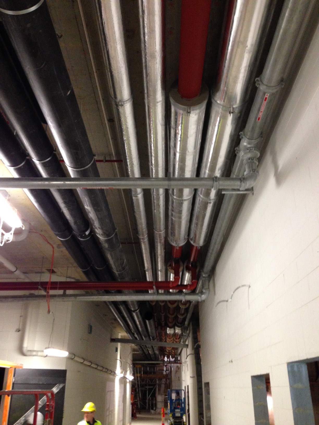
But we have made progress!! We had to coach them through the welding process to ensure that they did sample welds, the welders where qualified, we inspected the welds and ensured they documented all the welds. We then had to ensure they painted the pipe as they were all rusty, now we are lagging the pipe and the Client (State) are not happy which will be todays work. We have completed everything to specification and closely monitored it so we could avoid this.
On a positive note I have been to multiple pump Factory Acceptance Tests (FAT) and Mark thank you the pump knowledge is invaluable, I even sound like I have some idea what I am talking about!! We have also installed our first switch board to the Northern Substation which comes in two parts for shipping which will be bolted together today. I also attended the FAT for that and again John the electrical knowledge was invaluable.
Overall a lot of fire fighting and less of what we should be doing but all great experience learning something new everyday.
C620?? Done. Blog No 5.
As I mentioned in reply to my previous blog comments I am now running with the construction of a 619.310m retaining wall but before I discuss the details and issues already surrounding this wall I will conclude with a few more details on C620 and another reflection.
I will also add a few photos to the shopping list style of activities I included for Blog 4 as I now have a working phone again!
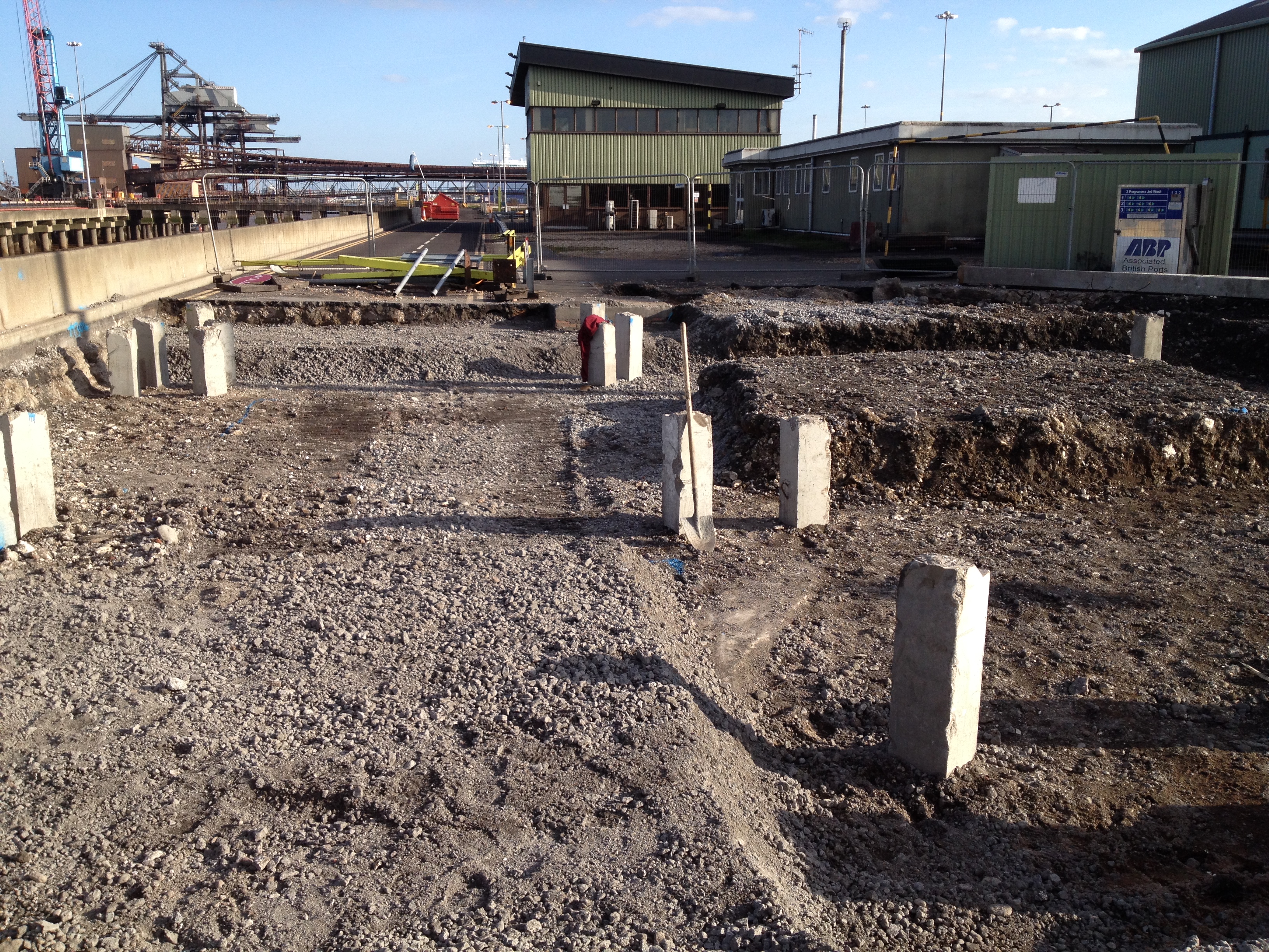
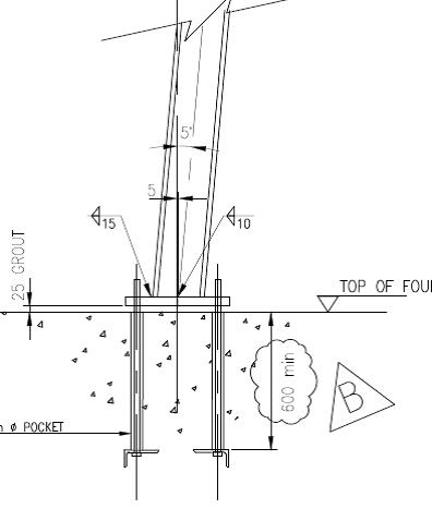
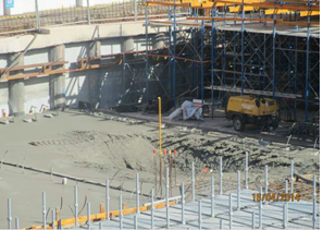
The foundation for Transfer Tower 535 (shown below) gives you an idea of the main foundation bases constructed (x3) and the type of layout of the services, deluge pipes, transfer beams, cladding upstands, gravel POL pits for the mechanical services, plinths and irregular off set bolt pads. All reasonably complex for a first timer!! The first picture below is taken from Blog 3 just after I had finished the excavation of TT535, the second picture shows the completed foundation.

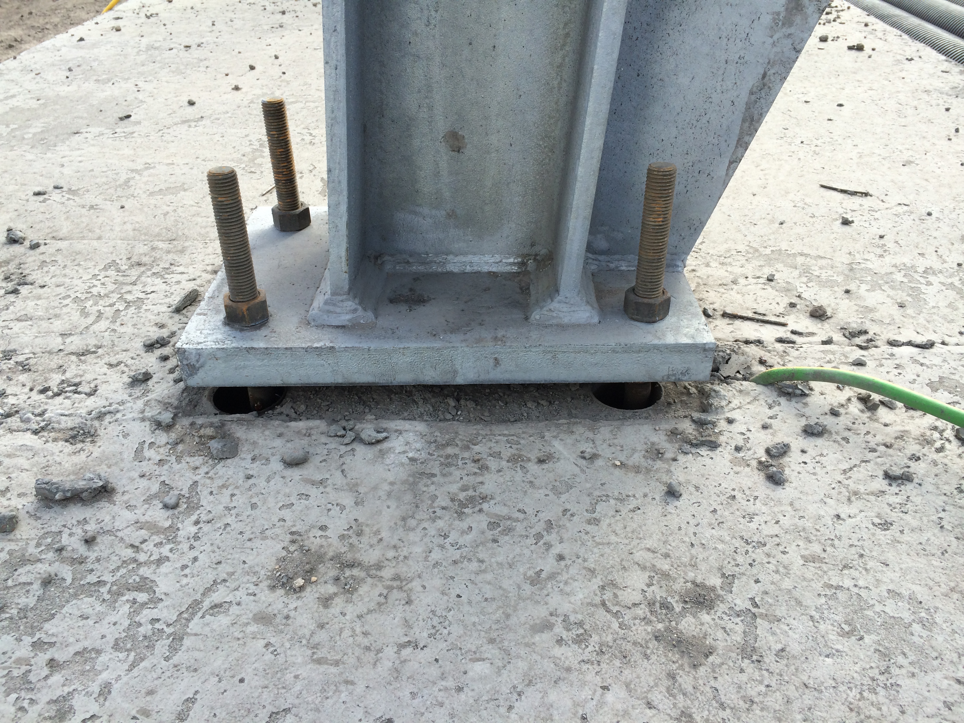
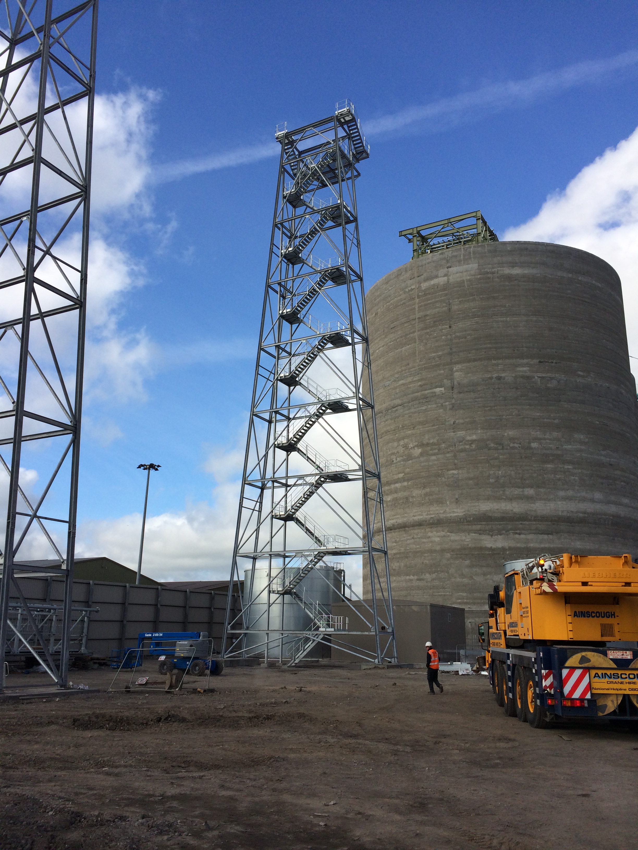
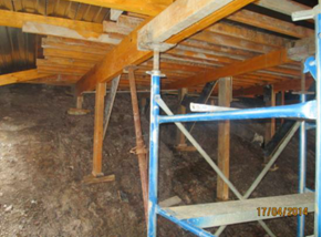
The steel trestles are now going up in earnest on the smaller trestle bases (4 of 8 to date) and they continue to fit – fingers crossed for the rest. The first photograph below shows a Trestle 10 column base plate fixed into position. The 25mm gap below the plate has been packed out and will be grouted to set the position. The photograph below that shows the exposed elements of the foundation for Trestle 10. Each slab had a deep foundation of 8 x PC RC 26m piles and housed 2 x bolt pads. They were connected by 2 parallel transfer beams running between the pads (now buried) that provided the platform for the small plinths, accompanying bolt pads and the stair beam. More importantly they reduce the risk of differential settlement across the 2 pads that the intolerant mechanical structure and services placed onto them cannot take.

Trestle 10 is now complete and is the largest of all the trestles taking the conveyor up to the top of the Biomass storage silos.
The bolt pads are made in advance and fixed into plywood templates that match the column base plate exactly. The bolts are placed into 60mm drain pipe cut to length acting as a void former to allow some horizontal movement for ease of placement and take out any setting out error. The trestle foundations were designed for compression and tension (predominately due to the wind loading on the high structures) and as such additional steel right angle plates were fixed to the ends of the bolts to increase the resistance to the tensile force. The design and finished in-place bolt pad (template removed) can be seen below.
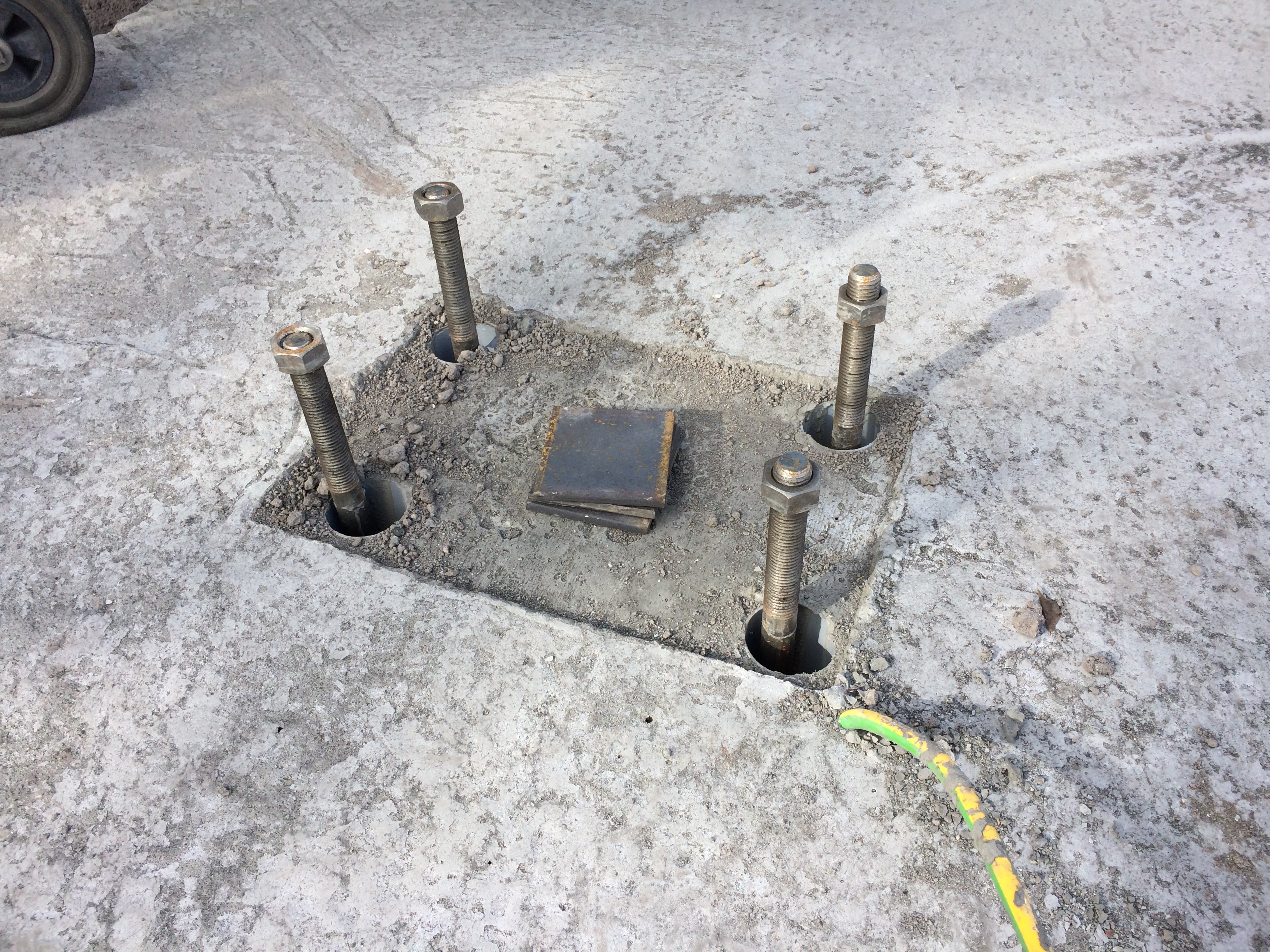
These were a pain to place as the steel cages had been pre-fabricated and lowered into place prior to the placement of the bolts and trying to attach the heavy steel right angle plates onto bolts through and 700mm deep into a 1000mm deep steel cage was tricky.
I set out the nails for the placement of the bolts, stringlines were used to set the correct position and wooden cross bracing was used to fix the pads to the correct height and location. On the first foundation featuring these plated pads we used the addition of steel tying wire to hold them into position. I quickly discovered this was not enough.
Issue. The specification for the C32/40 concrete used in the C620 foundations was for consistence class S3 and a max W/C ratio of 0.45 giving a target slump of between 100-150mm (-20mm, +30mm) and generally the team liked it at 150mm+ for ease of placement. On one of the initial pours where these particular plated bolt pads were used we had an arrival slump of 90mm which I said was acceptable, as per the guidelines, and instructed the team to begin pouring. Due to the plates on the pads and the stiffer concrete mix the bolt pads rotated and moved significantly causing me a real headache as we quickly reset the lines and used various levers and improvised methods to work them back into position. This was all to the continuous backdrop of ‘I told you it was too stiff’ from the concrete team. Thanks.
Solution. For subsequent pours I held the lorry until the slump test was conducted, used a Graham Construction slump adjustment chart to get the predicted slump to around 150mm, tested it again (if there was enough time) and poured with much greater success. In addition I insisted that steel Z bars were used to brace the bottom of the plates to the top of the steel cage and they were quickly tacked into place by the welder. This resulted in a much smoother pour and significantly less stress/abuse for me.
Reflection. The reflection from this issue was one of quality control and the difficulties surrounding it. Enforcing it has made me unpopular on a number of occasions. This site is over 18months through the project and the team of sub-contractors have been together since the start, working with LaFarge the concrete suppliers. ESG are sub contracted to conduct a slump test on all loads and 1 cube test per day or every 10 lorry loads however it has become site practice to get the cubes done every 20m3 (approx. 3-4 lorry loads). I have witnessed poor practice on a number of occasions across the site as a lorry would turn up, the slump and cubes would be taken and then the mix would be wetted up to suit the pourers and placed. On my section, to prevent this, I would have to physically stop the wagon, insist on the slump being taken, adjust the mix as required, slump test it again and then get the cubes taken. As long as I kept it within the guidelines stated above, which at the upper end was more than workable enough for the concrete team, I could not understand their reluctance to do the right thing? Quality control and assurance are vital in this a marine environment and I could only put it down to the additional time (probably no more than 10mins) it took to complete as they just want to ‘get it done’ as the subcontractor is paid per m3 of concrete poured.
There were obviously more learning points and issues that I have captured for my DO’s but having discussed responsibility, speed and accuracy, services, piling problems and solutions, more piling problems, construction methodology, ground investigation, risk, concreting and quality control I feel I can put C620 to bed for the blogs and save some final bits for AER2.
I will now start drafting a blog for another issue I already have for my retaining wall!
All trains from Victoria CANCELLED…….
Well today I was in my element utilising my military skills and my search advisor knowledge! It involved 5 police cars, 3 fire engines, an ambulance, the evacuation of the site, closure of Battersea Heliport and all train lines coming from Victoria. At around 1430 Hrs one of the engineers came up to the office saying that the piling rig had dug something up that could be UXO. Being the only person that vaguely knew one end of a bomb from the other I agreed to go and give my expert guestimate of whether we should be running for cover.
On arriving at the piling rig I found this:
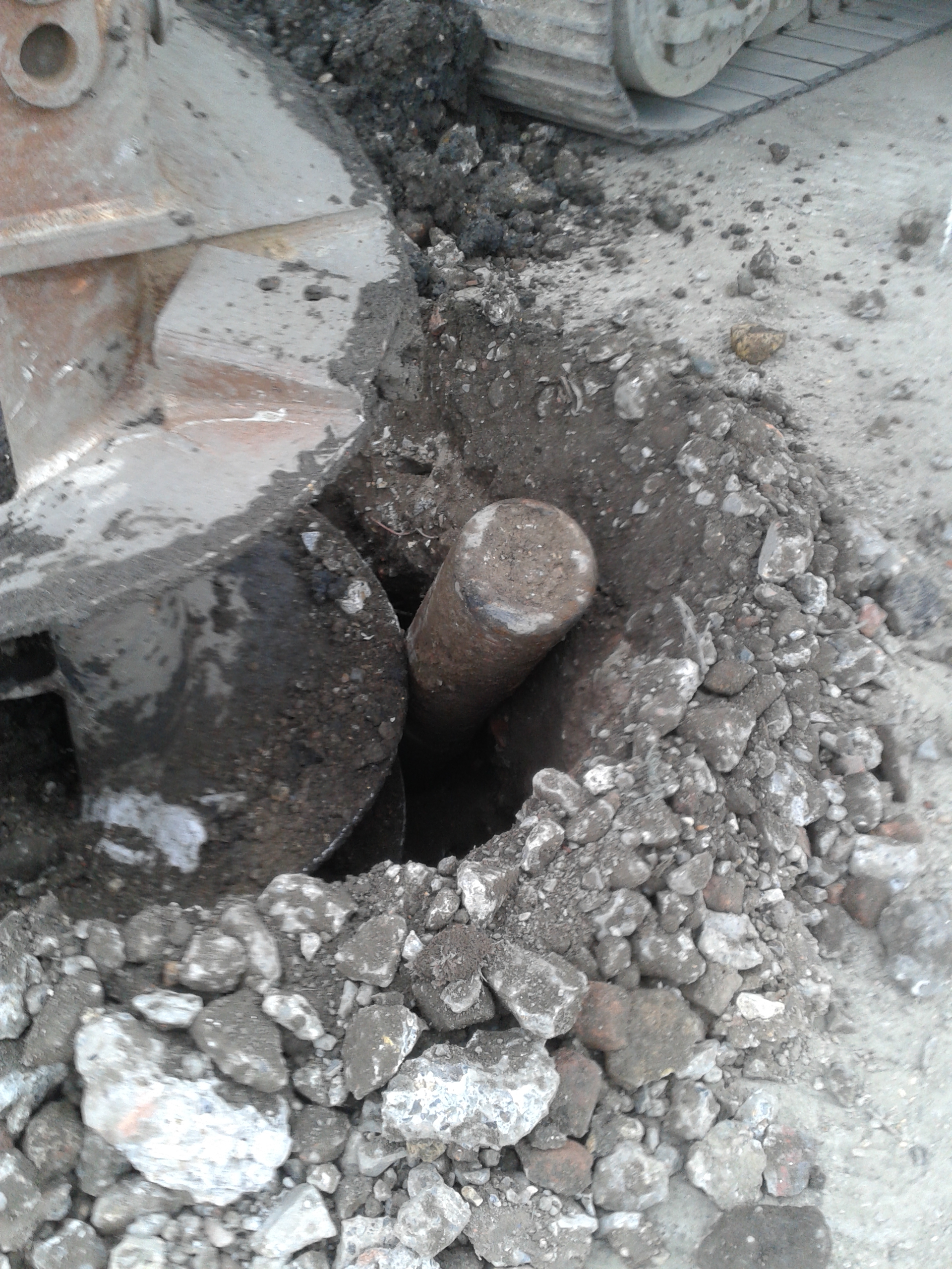
It was around 150mm diameter all the way down with no tail fins or pointy ends so I was 90% sure it wasn’t going to start ticking at us. I took some photos to brief the services and then cleared my area of responsibility of operatives. As the site was getting evacuated I found the piling rig operators and used the search advisor questioning technique to find out what they were doing when they found it and what actually happened. The rig was drilling the pre-bore for the casing when it hit a metal obstruction about 1.5m BGL. On moving the auger forwards and up, it uncovered the metal object that started hissing. At that point the rig crew stopped work and promptly left the area to raise the concern. We got the site evacuated and after around 45 minutes 4 police cars turned up.
I ended up briefing the police and showing the photos with the senior construction manager and an ex-RE policeman went down to have a look. He confirmed our suspicions that is was more likely to be an oxygen or acetylene cylinder and the police decided to establish a 400m cordon. With the train lines around 30m away and the cylinder pointing straight at them and the flats the other side of them-all the trains from Victoria were cancelled and the flats started to be evacuated. Finally the fire brigade turned up and I had my briefing map and photos ready. It reminded me of the old 4Cs operation we got taught on PDT for Iraq. After seeing the photos they reduced the exclusion zone to 200m and they sent some guys with breathing apparatus to go and check it out despite the fact we had been stood next to it over an hour before!
To cut a long story short, they confirmed what we had told them and went with the construction manager’s plan of attaching some strops to it to support it and reversing the auger to lift it from the hole. Low and behold it worked without going bang and everyone went home for tea and medals and the trains set off again.
Here’s the culprit:
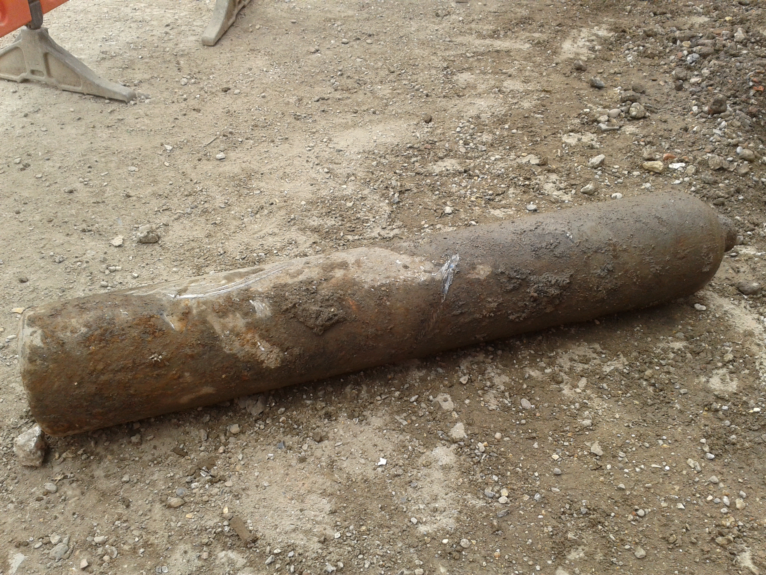
We are not sure exactly where it came from but it looks like it was between our pile mat and another piece of terram. It may have been buried during the backfilling of a previous dig or development prior to us being on site. It is likely to throw up a whole world of debate about whether excavation and piling on the site is safe as if they had struck the cylinder straight on it could have exploded. It will also be interesting to see whether the client ends up footing a bill for the closure of the railway line or whether incidents like this outside our control are excluded. One thing I will be implementing on site is a proper laminated briefing map and some advice on how to control incidents. I was amazed with how many people rushed to take the afternoon off, leaving a couple of people to deal with everything. Even the police and fire brigade didn’t really seem to take command and control as I would have expected them to do. I am more institutionalised than I thought!
Charity Engineering Development
Early in my in my attachment volunteered to take part in a charity cycle ride from London to Paris, of course wanting to prove my physical prowess I instantly said yes with little knowledge of really how far it was or what the charity did. The weekend just gone was the date set for the cycle ride and I’m pleased to say the team of carefully selected office athletes set of from outside of Liverpool street station on Friday morning and arrived under the Eiffel tower late Sunday afternoon. Having now completed the cycle ride and having hounded others within the office for sponsorship I thought I better really understand what it was i raised money for, i knew it was for third world development but what was the money actually for…
The charity is called Engineers For Overseas Development (EFOD) and is a voluntary organisation that aims to enhances the training of young professionals by challenging them to deliver development projects overseas. Over the last 13 years EFOD have delivered a diverse number of projects to communities in central Africa (Uganda, Zambia and Ghana) .
Examples of past projects include:
• A medical waste incinerator at Kumi Hospital, Uganda (EFOD North-West);
• The design and construction of a footbridge over the Kanakantapa river in Zambia (EFOD Wales);
• The Sewing School in Kpone Saduasi, Ghana (EFOD South-West); and
• A community centre for a women’s co-operative farming group in Koutulai, Uganda (EFOD West Midlands).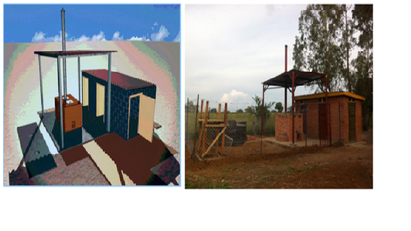
Designed and Completed Incinerator, Kumi Hospital
This year’s project is the improvement of infrastructure critical to the running of a hospital in Kuma, Uganda. The scope of the project for 2014 is; to improve the water pump, currently a broken diesel pump, to improve supply to the hospital, construction of more sustainable and hygienic latrines, improving the laundry facilities within the hospital.
The projects looks to utilise and practice junior engineers in applying engineering principles to design both structures and M&E services. The junior engineers are also responsible for the commercial process and al other aspects of managing the project from concept through to final handover. While not all the engineers will travel to Uganda all will contribute to the project. Having had a little experience of delivering engineering projects within Kenya and Afghanistan i was asked if I might be able to assist by means of reviewing projects and imparting any advice to the junior engineers on project managing such a project.
During the two short periods that I attended with the EFOD engineers and during the review of their initial designs and concepts the key themes that I feel I helped to develop area as follows:
Sustainable – considering environmental impacts, future community needs, and the longevity of the design
Buildable – with local resources, taking into account local knowledge, available expertise and skill levels
Maintainable – using a maintenance scheme appropriate to local skills, which are strengthened through EFOD provided training
Affordable – delivering required outcomes with the funds raised
Ground reality – H&S regs will not be to the UK standards and would be very hard to enforce, therefore work with what is acceptable risk and implement measures where possible.
I am the god of hell fire (testing)!!!
In my final action as a Materials Team geek, beofre moving down to site, I found myself responsible for demostrating the competancy of the fire protection in the tunnel lining. This has become a bit of a poisoned chalice, as the testing the first time around was so badly managed and delivered that it was deemed uncompliant by Crossrail Ltd, at a cost to the contractor of £48000. In the context of this contract, pocket change, but in terms of reputational impact, quite costly. As chalices go, poisoned ones are my least favourite…so feeling a little bit like the fall guy, I got stuck in…
Regulating Layer Function
As discussed in previous blogs, the tunnel lining comprises a series of layers which fulfil a specific and discrete function; structural or serviceability related. The two regulating layers are designed to smooth the substrate, which in this case will be the primary and secondary layers consisting of a Steel Fibre Reinforced Concrete mix. The smoothing function covering rogue steel fibres is pertinent in the case of primary lining regulating layer, as the polyurethane waterproof membrane will be applied over it, running a risk of the steel fibres protruding through it, and casuing discontinuity. A secondary consideration is to prepare the surface for efficient waterproof application. Cratering, or large undulations in the profile of the primary lining will lead to an excessive use of spray waterproofing, which is an expensive construction material. (£20 per kilo)
Typical Lining and Thicknesses
The secondary regulating layer will form the innermost sprayed layer of tunnel lining. In addition to providing a fibrefree surface as above; it will also provide the critical function of passive fire protection to the tunnel structure.
Specification
The secondary regulating concrete mix is a relatively simple design specified to achieve C28/34 at 28 days, with a 600mm flow measurement on arrival at site. This mix has an increased retarder (1%HCA from 0.5%) from the original design after issues with the concrete life in the early stages of the trials.
In the context of the fire protection, the mix contains polypropylene fibres, or polyfibres. Following the first fire in the Channel Tunnel , in 1996, a major test program was undertaken by the Rail Link Engineering Design Group on behalf of the Channel Tunnel Rail Link. It demonstrated that the use of polyfibres in concrete significantly reduced the phenomenon of explosive spalling, and thus maintain the integrity of the protection of the structural lining. Polypropylene fibres are now specified in most public use tunnels and underground spaces.
Testing
1. Sampling. The specification dictates that the samples should replicate the tunnel lining as closely as possible. To that end, moulds were constructed from low absorbing plywood to the dimensions dictated: 1700x800x500mm. The panels would then be constructed using a 450mm thickness of secondary lining mix, followed by a 50mm layer of sprayed regulating mix. Two panels were fitted with conventional reinforcing bar, to replicate areas of cast in-situ secondary lining, whilst two were constructed with steel fibre reinforced spray secondary concrete. Thermocouples were installed to measure temperature at the location on the rebar, and at the interface between secondary and regulating layers. The phot below shows rebar supports which hold the thermocouples in place as dictated by the specification
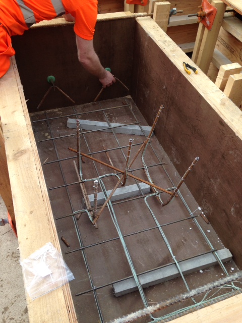
Fig 1. Low absorbing ply moulds, with thermocouple placement and lifting eye detail
2. Storage. The secondary layers were poured whilst the moulds were flat. Once cured, they were lifted to near vertical and sprayed with the regulating layer, at pit bottom in order to replicate closely the conditions in the tunnel. The moulds were struck witin 24hrs of the construction and the panels were then shrink wrapped for protection and to restrict the evaporation of any moisture from the back and sides of the panel. The panels were then lifted and transported to the BRE facility in Watford (a journey of approximately 22 miles) after 1 week. The samples were unwrapped and moved to a storage area. The temperature and humidity were controlled for the remainder of the 28 day period at 40°C and 60% humidity.
3. Test Description. Test samples are each exposed to the same temperture/time exposure, as per the EUREKA fire curve dictated by the specification. The test rig is shown in Fig 2, below and the specified target temperatures and allowable deviations shown on the curve, here EUREKA TempTime Curve
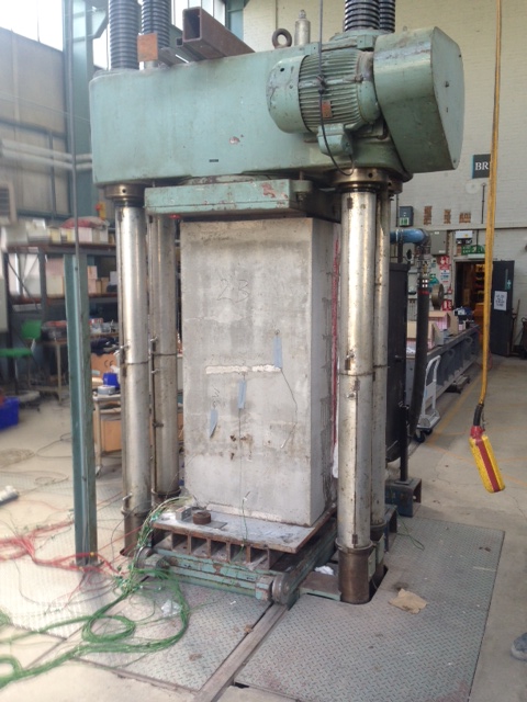
Fig 2. Test rig. Rear of the sample in view
Test Procedure
- Sample transported from controlled storage and weighed prior to test
- Specimen is placed in test rig (500 tonne compression machine) and loaded to an applied axial stress of 5MPa, in order to replicate the hoop stress seen in the tunnel lining.
- The furnace was brought against the face of the specimen and edges are sealed to prevent heat loss.
- Specimen is then heated in accordance with the EUREKA curve using a gas fired furnace. Controlled cooling will take place as part of the curve.
- Following the test, the nature and extent of spalling would be recorded
- Cores to be taken and crushed to test the residual stregth
Acceptance Criteria
The regulating layer would be deemed compliant if it adheres to the following criteria:
(1) The surface regulating layer is to be considered as sacrificial. The depth of spalling of the surface of the main secondary lining shall not exceed 25mm.
(2) The temperature recorded at the level at which the waterproofing layer will be installed should not exceed the temperature at which it may degrade, as advised by the manufacturer of the materials.
(3) Concrete cores- compressive strength of the concrete samples should not be less than 70% of the original design compressive strength at 28 days
(4) The temperature recorded by thermocouples attached to the reinforcement should not exceed 450 °C.
Discussion
In the event no spalling was witness during the test, with the exception of the 3rd test. Here, the spalling was restricted to a localised area towards the bottom half of the test panel. This occured relatively early in the test (18mins). This caused some consternation, but on inspection the spalled area was less than 25mm thick, so in fact the regulating layer had performed its function: as a sacrificial layer. No damage was recorded to the secondary lining.
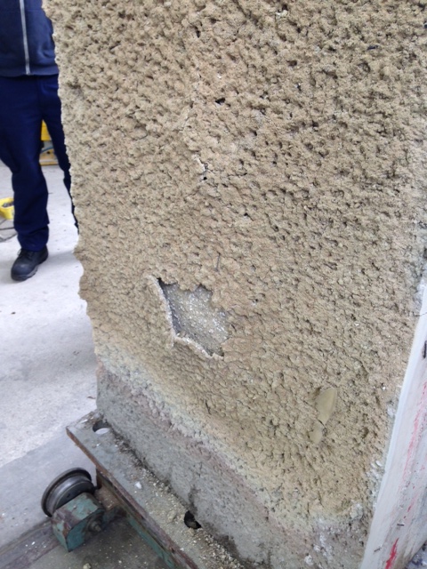
Fig3. Minor spalling in regulating layer only
BASF specification for MasterSeal 345 (waterproof membrane) advises that the product begins to degrade at approx 250degrees C. The highest recorded temperature at the interface between secondary lining and reg layer was 50 degrees and therefore well witin the safe envelope to avoid degradation of the waterproof layer
Cores taken subsequently was mandated to demostrate at least 70% of the 28 days strength of 28 N/mm^2. In fact the lowest recorded stregth was 65 N/mm^2, easily fulfilling the residual strength requirements.
Finally, thermocouples at the extreme end of the rebar, closest to the heat source recorded temperatures not exceeding 120degrees…well within the 450degress advised by the manufacturer.
The test result was a success, and following submission of the Materials Compliance Report, was accepted by Crossrail. In fact, what this demonstrates for me is that in the event of a fire in the tunnel, the structural integrity of the lining will remain intact, thus allowing escape and avoiding catastrophic collapse. However, and perhaps significantly, the test suggests that the cost of remedial action to bring the tunnel back into action would be minimal by comparison. Without degradation to the secondary lining and waterproof membrane, the cost would be in the re-application of the relatively cheap regulating layer, at a thickness of 50mm.
Captain’s Blog, Final Entry
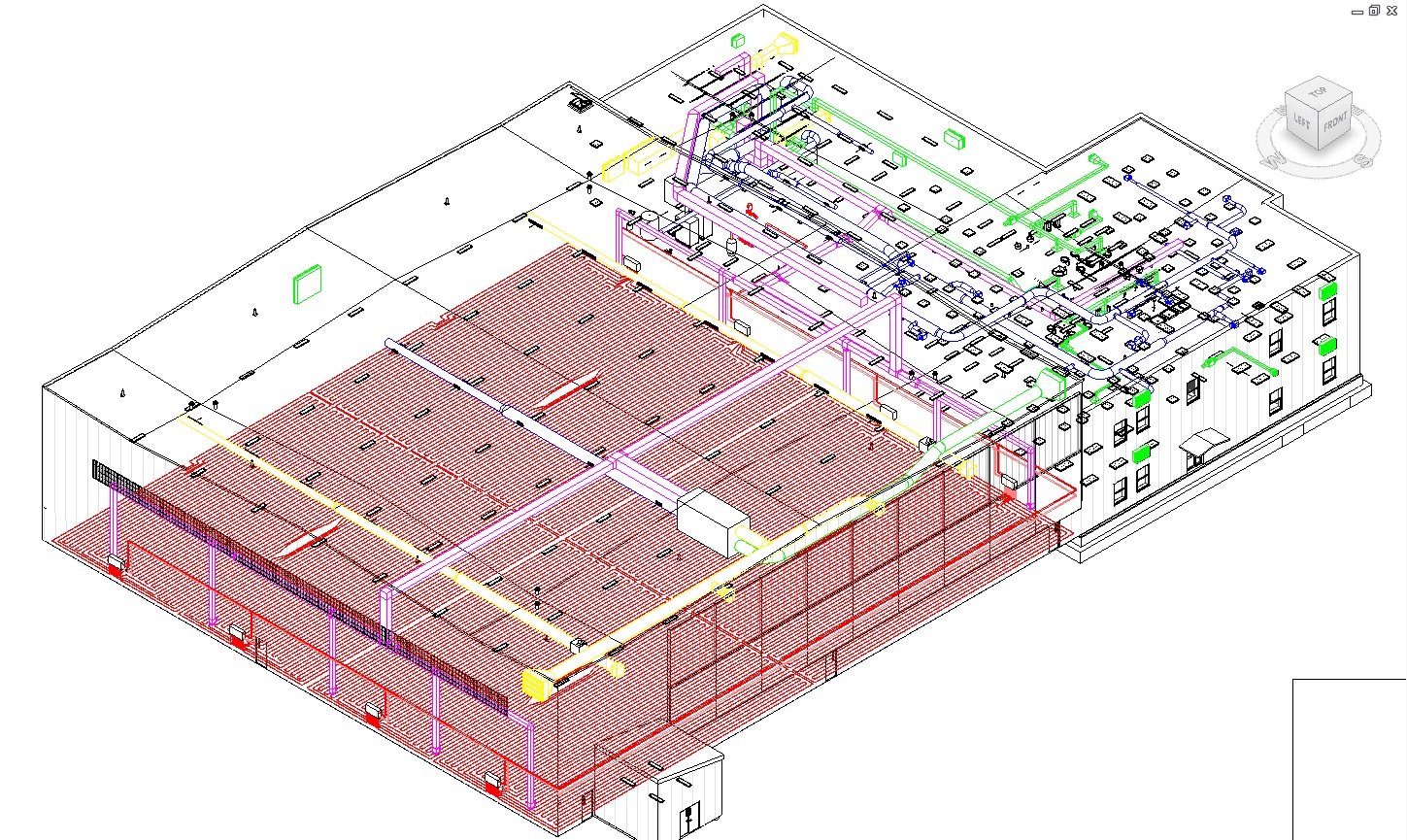
As I wind down in the design office, I will give a quick recap of the Fort Drum UAV underfloor radiant heating design I have (mostly) completed. Having calculated the likely heating needs of the building using modeling software I set about designing the radiant system. From the total heating load required it is necessary to work out how much this load is per hour per square foot. In my case this was 96 BTU/h/ft2 which is double the recommended capacity of radiant floor heating which is limited to 50 BTU/h/ft2. In real terms this means the floor can provide half the heating needed and an alternate source, gas powered radiant heaters in the roof in this case, is needed. From this the floor temperature and supply water temperatures fall out from the manufacturers design parameters based on flow rate. If the full heating demand is used the concrete would have a surface temperature of 117F (48C) and would need a supply water temp of 180F (81C). In the International Building Code this is too hot for concrete which could undergo thermal shock if these temperatures are used. Instead the optimum is 90F(31C) floor temperature with 120F (48C) supply water with a ΔT of 20F (6C). The next stage is placing the pipework on the design. Without knowing the lengths of pipe you need in each run, you cannot see how the runs will fit, what lengths of the individual loops are (700ft is a rough maximum but it depends on several factors) or how many manifolds are needed. With 4 zones to heat I thought I would get by using one manifold for 10x 700ft loops per zone but the total flow of 50gpm in the system was too much for one manifold which could only take 45gpm. Having split each zone in 2, I was able to size the pipes for the system, from the under floor to the supply pipes, in Crosslinked Polyethylene (Pex) which prevents oxygen from dissolving in to the system and causing rust in boilers. With all the pipes sized and laid I calculated the pump size based on the static pressure (with a dual pump, lead/lag system to allow for failures and maintenance and the use of 40% glycol (for the extremely cold winter should the heating system fail)), the size of the expansion vessel needed and the heat loss from the distribution pipe work to ensure that the boilers are correctly sized. And that is it really. For interest, here is my finished design (ignore the duct work):
 <
<
There are still some issues to resolve. Sometime this week the orientation of the trench drains in the centre of each zone was rotated by 90 degrees which has meant a last minute redesign. Originally my pipes were perpendicular and able to go under the drains. Now they are parallel they have to go round. The main hot water system is still not complete so I have not integrated that yet but that should just be a case of connecting to the header when it is designed. I am also completing the controls which are very simple. Essential the thermostats in each zone dictate the temperature that heating is necessary at whilst there are alarms to indicate pump failure, low flow rate and low temperature. The original brief called for a door switch so that the system would stop if the hangar doors opened but this only really applies to forced air heating systems where the energy could be blown out of the building. As radiant heating heats the object not the air, this is unnecessary.
A little bit more of a technical post but not a bad place to finish.
And in other news:
The gun debate continues after yet more school shootings, the East Coast is currently under several flood watches because of the unseasonable rain (8 inches due today) but at least it is warm and a soldier has been freed from teh Taliban but did he desert in the first place? I now have a week to sell the cars and electrical goods, reduce my possesions down to 11.5m3 (sorry kids the toys are going) and make the furniture look like new before the Embassy takes possession of it again. See y’all in Phase 4 if not before!
Mr Cropper is too blunt
Things are picking up on site. The excavation has now been completed on the first to piers and the piles are being broken down. The hydraulic cropper arrived on site (after much delay it ended up being shipped in from the UK), and it has promptly fell on its arse. It works fine, too good really as it is mangling the reinforcement and strand within the piles that need to be tied into the pilecap reinforcement. There just seems to be too much congestion in the pile for it to work as intended. The helical cage combined with the strand and the normal 24mm bars seems too much for it. The photos below show what the pile cropper in action and what its first and fourth attempts produced. There was an improvement in the technique, but it was still causing too much damage from a QA point of view.
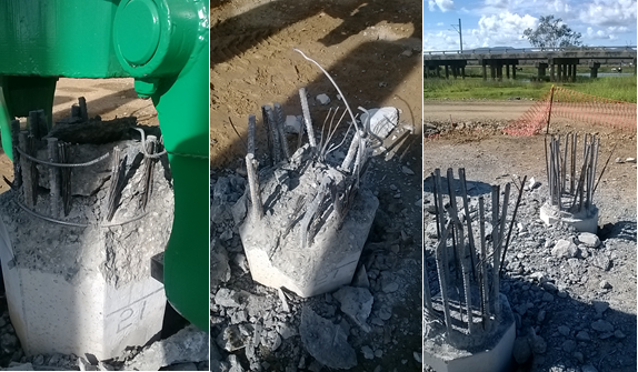
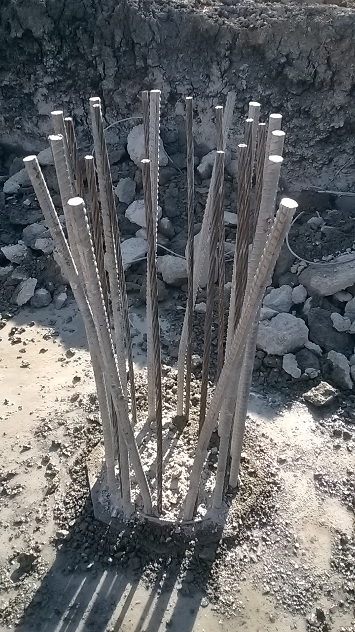
Below is the pile that was broken out through a combination of a rock breaker on the backactor of a LWT and men with jackhammers. I know Joe had great success with the cropper but it seems that the combination of high grade concrete (should be 50MPa but in 28 day crush tests its reaching over 70MPa) with lots of reinforcement is too much for it.
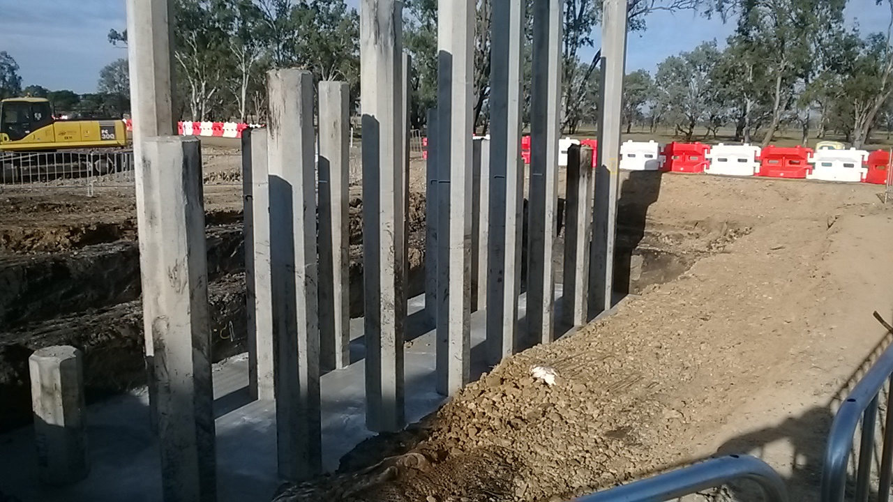
The excavation has been stepped back at a 1:1 bench with a further stand off equal to the depth of the excavation (to make a 1:2 slope). The same geotechnical consultant that is certifying our crane and piling pads has looked at this and he seems more than happy with this for normal traffic. We’ve looked a lot more closely at the loading for the 80T rough terrain cranes that will be lifting the forms into position. Things still seem good when considering the bearing pressures. The biggest problem seems to be passage of information to the guys doing the work on the ground. When barricading was put in to maintain this stand off all was good. I then found out it was moved to get an EWP in closer to the edge for access to something. It seems the workers thought the barricade was to prevent falls into the excavation, and the supervisor hadn’t passed on it was for standoff. Its now been covered in the daily prestart and I’ve spoken with the crew on the ground too. I’ve spoken with the geotechnical consultant about the benching and how long it will be safe for, I’m anticipating a few questions from John on this….
In other news there are still dramas over steel reinforcement in the headstocks. The cages for the columns have started to get tied by the steelfixers. The formwork for the headstocks still requires modifications and I’ve been in touch with the designers Bonacci about modifying their drawings. One of the big questions is how to remove the support frame around the column once the headstock has been poured. This might have to be another blog on its own.
I’m now going to elaborate on what happened on Tims site for the civils that maybe don’t read the E&M blogs. All this information is from either Tim or the John Holland internal safety alert system (JHET). Its been raised on my site and across John Holland as a whole, its of particular relevance as I have temporary excavations currently in place and the upcoming formwork installation too. It seems to be a good way of passing the information and making sure that the group as a whole learns from mistakes – I’m not sure what the others in Oz think about this? Is there an equivalent system on Crossrail?
Description of incident:
A Subcontractor concrete work crew were pouring concrete in Zone 2, Basement 2, Pour 1. During this work, the Bondeck and supporting formwork/falsework, partially collapsed resulting in approximately 8 m3 of concrete in a 40m2 area to fall through deck to lower level. The concrete work crew identified the failing deck and evacuated the area prior to collapse. No personnel were below the deck at the time and there were no injuries as a result of the incident. The site was immediately evacuated.
Contributing Factors
• 32mm of rain overnight prior to the incident affected the stability / integrity of the base plates and tombs on the batter between B2 and B3.
• The Formwork Engineer issued Formwork certificate 5 days prior to the pour, providing opportunity for external factors to change or affect the integrity of the formwork structure.
• Temporary works procedure not implemented adequately
Lessons learned
• Where formwork is supported on two types of ground bearing (e.g. natural earth batter and slab on ground), specific design documentation, inspection regimes and certification processes need to be implemented.
• When Engineer certification is provided for temporary works well in advance of activity and bearing on non-unified material, due to unforeseen delays with potential for alteration, modification or damage to the temporary works, a re-inspection / certification process needs to be implemented
Back online! Blog No. 4.
I’m now back! After a reasonable period of time offline in the blogging world here is blog no 4.
My work has continued at breakneck speed along C620, hence the lack of blogs, and for those who can recollect blog 3 I had just finished the piling and had started the excavation of the foundations.
So here is a shopping list of what I have facilitated or directly completed over the last couple of months:
17 piling platforms excavated, backfilled and CBR tested.
170 PC RC piles, positioned, driven, tested and cut.
8 Steel H-Section piles, positioned, driven, tested and cut.
28 permits to dig completed.
Excavations set out.
1000m3+ of material excavated.
Heights checked.
22 service ducts and water mains positioned, excavated and placed.
136m3 of blinding poured.
Heights checked.
170 PC RC piles marked and cropped to expose rebar.
8 Steel H-Sections cut and modified for a deep foundation in tension.
Over 200m3 of groundwater pumped out of excavations.
Over 200 nails positioned for setting out.
Reinforcement steel fixed, positioned and checked against RC drawings.
Heights checked.
56 earthing cables set out and welded.
Over 1kM of shuttering placed.
Height, vertical and horizontal cover checked.
Foundations blown out.
69 individual bolt pads positioned.
Heights checked.
500m+ of chamfer filet set.
Heights checked.
11 notification to pour forms completed.
581m3 of C32/40 concrete poured.
60 sets of cubes taken.
Heights checked.
Shuttering struck.
Excavations backfilled.
1 large QA folder still to be completed!
The last base was poured today and I now have over a week’s worth of QA paperwork to complete for the whole section. 3 of the steel trestles have been constructed onto the early bases and they all fitted perfectly onto the bolt pads – so far, so good – fingers crossed for the rest!
So what have I learnt? Loads of stuff! But for now ill conclude the piling episode with a few remarks as I know those who followed my previous episodes cannot wait for the conclusion?!
As you will remember many PC RC piles broke, steel H-Sections were used as replacements. This was the focus of TMR1 and as some of you won’t be lucky enough to read that particular gem so I will expand on my observations.
Risk.
The risk within the piling sub contract was shared reasonably effectively between Graham Construction and Balfour Beatty Ground Engineering (BBGE) and reads ‘‘The subcontractor has not allowed for overcoming man-made or naturally occurring obstructions (whether they are below ground, surface or overhead) which impede, or deflect the Works, or result in them failing to achieve the design and/or specification requirements. Any additional time and costs associated with overcoming or attempting to overcome such conditions (including but not limited to set ups, displaced and/or damaged works, replacement and/or additional works, lost consumables, and damaged plant) shall be in variation. The subcontractor however has allowed for the cost of 30 replacement piles on this occasion. Any further replacements will be a variation in accordance with this clause. Should less than 30 replacements be used the cost saving shall be shared by both parties’. This figure of 30 piles was agreed by negotiation as initially BBGE would only accept 10 breakages as part of their standard contract. It still proved an underestimation as these replacements had been consumed during the first stages of the operation whilst piling for the RC storage silos. Subsequent replacements were charge at the agreed original pile cost calculated by the length required: 18m and below at £450 per pile, 18m and above £620 and driven via a variation order. All the piles for C620 were 18m and above and therefore the replacements were charged at £620 per pile with the additional cost of pile testing at £120 per pile (1 in 10 tested). This risk of breakages had been identified by the Graham design team from studying the borehole data and hence the 30 pile float had been negotiated. This risk and associated cost was covered by Graham Construction.
However BBGE also took a risk within the contract. The calculations conducted by BBGE detailed the design depth for the piles to achieve the specified working loads across the various areas of the site; the price was quoted from these calculations. However the piles were installed to a dynamic resistance, or set, calculated using the Hylie formula (less than 25mm per 10 blows) and therefore the actual length varied from those suggested by the static calculation. The additional sections required to achieve the extra depth and set, beyond the calculated and quoted for depth, were at a cost to BBGE. In addition, BBGE priced the contract on the number of piles driven at the calculated length, not on site time. The re-organisation of the piling during and after the breakages resulted in an amount of standing time charged at a set rate, higher for the first hour and then reducing for subsequent hours. This time whilst at a cost to Graham, was at a greater cost to BBGE as the greater profit for them is in the driving of piles succinctly and quickly. Whilst the rigs are standing the BBGE profit is reducing and it also delays the rigs from moving on to other sites where the more profitable piling can continue. When looking at the number of breakages across the whole site coupled with the additional lengths required on a significant number of occasions, it is quite possible to envisage a reduced profit margin for BBGE.
I feel that the risk was actually well shared by both parties. On the surface it appears that the majority of the risk was held by Graham with the low number of potential breakages (30) written into the contract but on closer inspection of the ground investigation data it was clear that deeper piles would likely be required and hence a risk to BBGE.
Ground Investigation.
A large amount of ground investigation data was available to both the designers (HBPW) and BBGE as the pile designers from a series of surveys conducted at various times across the site from when it was reclaimed from the sea in the 1990’s. From the vast amount of data available BBGE took the unusal step of not using a design borehole to design the piles but used the actual borehole data. Whilst not particularly risky the boreholes used where not, in my opinion, the ‘worst case’ boreholes that in my logical mind would choose. In addition not all of the data was referenced by the main designers for BBGE to use to design the piles and this missing data contained the worst case boreholes, including the one closest to the area where I broke all the piles that had a 2m deep layer of chalk made ground. Has all the information been thoroughly considered it is likely that the piles may have been redesigned at a deeper depth, costing BBGE less and invariably saving on the number of breakages. This in turn would have led to a reduced cost to Graham and the steel section solution being reached earlier, if not from the outset.
The ground is a risk. The importance of GI cannot be underestimated and whilst in this case the problems were not from the lack of information, as is often the case, but from a lack of exploitation of the available data.
Apologies for the long blog and the lack of pictures. My iphone slipped out of my pocket on Thurs afternoon, and as is always the case with sods law, got immediately run over by a dumper with all my exciting photos. Happy with that.
Finally some more work
But first thing first. A bit more on how projects develop in Projects and Mods.
The Process. As you read in my last blog the BP process goes from Appraise –> Select –> Define –> Execute. The precursor to all this activity requires the that customer, read platform, submits a request for work (WFR) form which is considered by the Project and Mods Team. Should it be deemed suitable the proposal is considered in a screening study. This identifies in very broad terms who the stakeholders are, how much, how long it will take, possible options….. This will then define how the project is taken forward:
- C1 – Separate Appraise, Select, Define and Execute phases. (High Value and / or complex)
- C2 – Combined Appraise / Select and separate Define and Execute phases. (Medium value and a number of options to be considered.)
- C3 – Combined Appraise / Select / Define and separate Execute phase. (Low value and simple e.g. like for like replacement)
Responsibilities. Outside the BP structure Costain Upstream is responsible for delivering the screening study, Appraise and Select phases. Wood Group PSN is responsible for the Define and Execute phases. This split responsibility is mirrored in BP with there being a front end single point of accountability (SPA = project engineer) for the screening study, Appraise and Select phases and a Define / Execute SPA (me).
Funding. There are various sources of funding available to the project teams: operational expenditure (OPEX) and capital expenditure (CAPEX). OPEX is used to fund the screening, Appraise and Select phases and CAPEX is used to fund the Define and Execute. The OPEX budget is generated and owned by Projects & Mods. The budget is bid for annually by considering planned work on assets and adding an allocation for emergent work. CAPEX expenditure is controlled by the operators and it is made available to a project once a financial memorandum (FM) is approved and an approval for expenditure (AFE) is agreed by the partners. The FM approval is required prior to an AFE being agreed.
PROJECTS – THE OLD
Mungo Rescue and Fire Fighting Services
This is now in the final throes of the Appraise / Select phase before going forward into Define / Execute phases, at which point the responsibility for the project is passed to me. The next stage will be the submission of the FM and AFE. As a warm up for the submission of these documents I was ‘invited’ to present to the partners (First Oil and JX Nippon) so that they understood the need, schedule and cost. A hugely enlightening experience, dealing purely with the commercial side of the business.
Miller Helideck Lighting Trial
When I wrote my last blog I hadn’t appreciated that there was no money available to install the lights on the Miller. A hugely frustrating place to be in, considering that both the Logistics and the Safety and Operational Risk (S&OR) business functions were screaming out for the job to be done. After much toing and froing and a delay of 8 weeks a lump of cash was found. This allowed the project to get off the blocks. I was amazed to be on the receiving end of huge amounts of pressure to catch up 8 weeks on a 9 week project. Needless to say a face-to-face meeting squared that one. I still expect to get a note a week ‘asking’ me to make up the lost time!
The accelerated timeline that this is already on is starting to create problems. As a part of the Define / Execute Wood Group would typically confirm and specify details of selected equipment as the design authority. Because of the drive to get this offshore, the Define stage has been completely bypassed. This means that materials identified (not specified) by Costain in their front end work is being used to draw up bills of materials. (Specification sits outside the requirement placed on Costain.) So at the moment I’m attempting to move a project forward in which Wood Group is uncomfortable to progress as they have no specification to work from and they are unwilling to take the materials identified and work them into specifications. Having to sit down and hold hands to even get a rivet on a BoM.
PROJECTS – THE NEW
Andrew Sea Water Filter Failure
So the 2up boss came into the office and said something like ‘come with me boy!’. At which point I was the subject of a number of commiserative glances and found me feeling like I was back at primary school and had been summoned by the headmaster for a gentle caning!
Turns out one of the two sea water filters on the Andrew has suffered unprecedented corrosion and was on the verge of failure. Not a huge concern today as the platform is not producing, however, once the platform comes back on line there will be no redundancy. Coupled with limited understanding of the corrosion mechanism there is a risk that the second filter may fail cutting off cooling water supply to the platform. This will result in a halt in production.
Initially a thinning of the filter vessel wall (Filter A) was identified as a part of a routine inspection. A significant thinning from 19.3mm to 8.3mm was recorded between Oct 13 and May 14. Further testing a week later identified a thinning to less than 2mm. At this point the vessel was isolated and the complete seawater duty run through Filter B. There has been much flapping as corrosion rates of 1mm / day are unheard off. As yet no similar corrosion has been seen on the B filter, however, on-line testing is ongoing to confirm the condition on the B filter.
There are two simultaneous streams of work ongoing to deal with this concern. The first being run by the asset is a repair of the existing 316L SS filter to bring that back into service. The second piece of work is to procure a replacement filter. There are at least four courses of action associated with procuring replacement filters:
- A – procure 2 x replacement filters made from super duplex steel.
- B – procure 1 x replacement filter to replace Filter A.
- C – procure 1 x replacement filter to replace Filter B, assuming that a Filter A is repaired and coated.
- D – do nothing (other than repair).
To date my involvement has been limited to attendance at option studies. At present the balance of effort is on progressing the repair. I am awaiting a WRF prior to initiating a screening study.
ETAP Sand Management
When the ETAP started operating the hydrocarbon flow line did not contain sand. Recently production has recovered large quantities of sand that is causing considerable damage to the produced water reinjection (PWRI) system. The PWRI system is used to maintain the well pressure, therefore, has a direct impact on production. (After bringing the pumps back on line the minimum failure interval is 1 day and the greatest is 6 weeks.)
The work scope is broad at the moment, but is looking at increasing the residence time of the hydrocarbons in the HP & LP separators and installing cyclones to remove sand from the process completely.
My involvement at the moment is limited to arranging an offshore survey. Normally a reasonably straight forward process, however, I’m having to submit waivers to divert from the normal processes. The risk of ‘fast-tracking’ the process is that the platform won’t be properly prepared for the visit and the survey will fail to meet all objectives, wasting beds on the platform – a cardinal sin.
ETAP Electrical Controls Upgrade (EECU)
I’ve had sight of this one for about a day now. It should turn out to be educational. It is mainly a subsea job (so outside the scope of Projects and Mods) but there is a topside interface that needs to be engineered and managed.
As far as I have been able to figure out, there is a legacy low insulation resistance (IR) problem with the power and control cables that run from ETAP ‘mother platform’ to the surrounding fields. The low IR is already starting to affect one field. (not sure how yet) The EECU is a proactive work stream to prevent similar problems occurring on other ETAP fields.
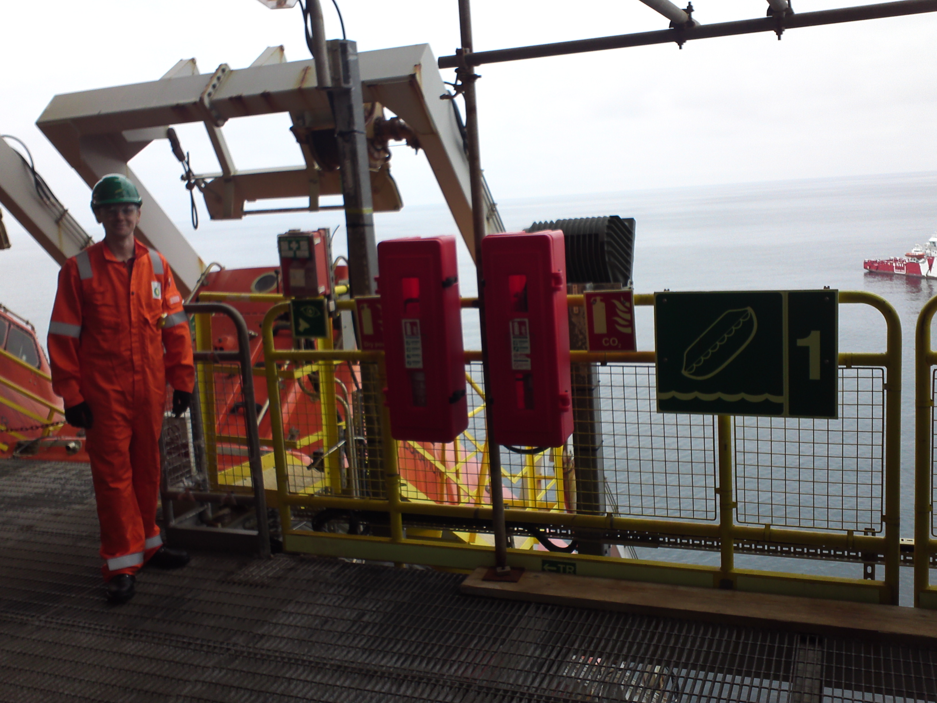
Offshore Experience
I went offshore this weekend to get a feel for the platform and to complete a detailed recce of all my jobs. I was offshore with another SPA, and we went round the platform and explained things to me. He is a structural engineer by degree so he did his best but he was a bit put of his depth. It was kept to an idiot’s guide level of explanation but it was very useful nonetheless. I managed to steer the conversation away from steel and concrete so we covered all the important issues such as chemical processes, piping arrangements, electrical single line diagrams, safety mechanisms, utilities including use of gas turbines fire water, potable water, storage of fuels and chemicals.
I had a detailed look at the jobs I am likely to encounter such as the Lifeboats, HP Cooler Replacement, Cabin Retrofit, and DC Charger Replacement. I also looked at some of the jobs that Imran is desperately trying to palm off on me. All in all, I feel like things are getting really quite busy and people are ready to trust me with much more responsibility.
The first thing I noticed was how seriously they take H&S, and quite rightly too. They termed it an open environment and it was where every crew member felt it appropriate to approach another person on the platform and point out any issues, or potential issues. They called it a Time Out For Safety (TOFS). It was good to see how the different systems work but I did notice that the permit to work system does slow things t like too many permits open at once so work can end up being stymied.
Jobs for the boys…
There are quite a lot of similarities with working in the military that would make ex-Army a good fit for working offshore:
Travel. Be ready for hurry up and wait, it was like travelling with the RAF. I had numerous delays but without any good reason. I was almost bumped off the flight at the last minute only to be told to turn up on the off chance. What should have been 70 minutes of flight time (50 in a fixed wing plane and 20 by helo) took 6 hours. However, the airhostesses are not overweight men in sandy coloured coveralls.
Workers. The average worker is just like a career sapper but aged 40 – 60. They like doing what they know and no more. You have to double check on them and make sure they’re actually doing as they’re told. The more senior guys on the platform are like the NCOs and WOs. These guys are dynamic and get stuff done and know what to do through heaps of operational experience.
Routine. Work routine was like being on operations. They work long hours and have a bit of down time in the evening. They then have time off to play hard. A typical rotation is two weeks on, two weeks off. The platform was full of workers and not a place you’d want to be without a busy job. A bit like being stuck in Bastion longer than you needed to be.
Food. The food was the same as being on operations, Aramark get everywhere. It’s no wonder the Army can’t get a good deal by playing hard ball with Aramark because they must have much bigger contracts to worry about.
Pay. This was a huge difference; the guy I was with was getting £90/day extra for being out there. That would mean he would only need to be out there for 34 days to get the same as our operational bonus for 7 months (not taking into account tax).
