Thermal Integrity Profiling
In a recent email conversation with John Moran, he asked me how we at the NLE were quality assuring the large diameter bored piles (2.4m diameter). Good question I said, see my next blog. Actually it applies to both the diaphragm walls as well as the rotary bored piles.
The walls of the Battersea Station boxes are constructed with diaphragm walls. For those who don’t know (because I didn’t really until I got here) how they are constructed here’s a brief explanation.
Diaphragm Wall Construction
The piling rig looks similar to a rotary rig except that it has a massive set of jaws, instead of a rotary auger. I believe a diaphragm wall works like a secant pile wall though I am open to being told that I am wrong on this one.


The rig can cut a panel 1.2m deep, 2.6m wide (or wider) and almost as deep as you want. Each panel is dug under a bentonite slurry to support the excavation during the dig. A deep dig can take up to 7 days to excavate. Once excavated a reinforcement cage is dropped in and it is then concreted using a tremmie pipe.


In TIP, a fibre optic cable is tied to the side of the cage. The technology uses a laser to shine a light through the fibre. Temperature is recorded by measuring the scatter backlight down the fibre at 1cm intervals. The system is accurate to 0.5°C.
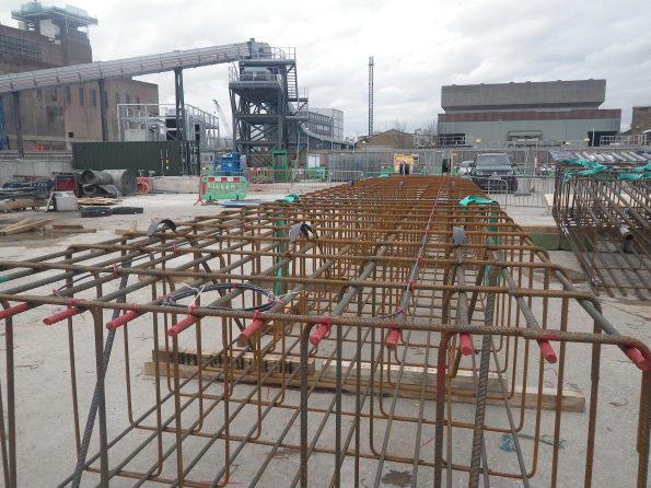
The Bottom Cage showing the Fibre Optic Cable already laid out and two reels ready to extend to next cage.
The instrumentation starts logging as soon as it goes in the ground and records for 48 hours after that. The output looks like the temperature diagram below.
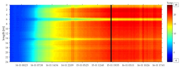
Thermal Profile Over Time
The cold spots around 6 and 14m depth correspond to the boxed out sections where we have rows of couplers that will eventually connect to our floor slabs. The box out in effect shields the concrete from the surrounding soil changing the thermal profile. This also allow us to confirm that the couplers are at the right height.
For comparison, the first three panels were tested with sonic testing and TIP as a comparison. Since it was accepted as a valid method of assurance only TIP testing has been carried out on each panel. As the graphs below on the right show, sonic testing can only verify between the tubes and not outside.
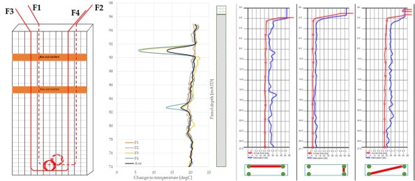
TIP vs Sonic Testing (L-R Lay out of fibre optic cables, TIP testing, Sonic Testing)
In short, this seems like it will be the future of assuring the construction in deep large piles. The advantages of easier installation, testing coverage area and time of recording make it worth the initial cost of the system.
I know that Expanded (Laing O’Rourke piling specialist) use thermo-couplers but I believe that they only record every 30cm and can be quite temperamental.
CFS-N205-2360000-CIV-RPT-00028_Iss1

Jonny you forget.that I’m a person of limited intellect.
The sonic coring ( on the right of the diagram is just plastic tubes down which an antennae and receiver are dropped so that the receiver receives an electromagnetic pulse from the antenna and the travel time of the pulse in concrete, if consistent, confirms the presence of consistent concrete between the two tubes . As you show the pairs of tubes tested are altered to confirm the presence of a consistent thickness of concrete between the pair – simples!
Now comes the thicky-mac- thick bit.
Somehow light in a fibre optic cable responds to the temperature in the surrounding temperature ( of concrete or otherwise). Don’t really understand how this is detected but let’s pretend I do.
If the cable is surrounded by concrete we’d expect to see the hydration temperatures rise – OK got that.
If the cable is the same distance from the surrounding ground as one of the other cables , the temperature response should be the same so the traces should lay over one another – got that ( albeit that F3 looks closer to the edge than the others in places)
If the cable were placed towards the centre ( but it does require some reinforcement to run it on ) then we’d expect to see a higher core temperature?
If the ground profile changed with depth and we used edge fibre lines ( as you show) we might even pick up geo horizons with depth, if different horizons had a slightly different attenuation on concrete temperature?
If we had an inclusion or bulge close to a fibre line we’d see an anomaly in the trace by comparison with the others?
So I think I get it – I just don’t understand all that back-scatter m’larky
John, all correct. I have never seen sonic core testing but your description sounds accurate. The tubes present an issue post construction as they require grouting and can easily get damaged whilst the cages are being lowered in.
The science in the fibre optic bit is actually not overly important other than to understand that it works. I’m told that all fibre optic is in-efficient and has a certain amount of back scatter (reflection) in the tube back to the source. The level of back scatter is measured in a number of wavelengths and is directly affected by the temperature of the fibre. It is possible to use this to also measure strain but this hasn’t been developed as much.
You are correct, in that the position of the fibre relative to the center of mass of the concrete will affect the temperature (closer to the centre more temperature). However as it is all relative i.e change in temperature over time, that is used. As long as the position of the fibre is consistent then the profile should be accurate. The heat profile is then plotted against depth and the known soil boundaries. Different soils will retain or distribute heat away from the concrete more than others. I have added a TIP report to the blog, which is written following each panel pour which kind of shows this.
Yes, a spike in heat at a depth would indicate that there may have been a collapse in the panel causing more concrete at that level and vice a versa. Of course this is usually expected as all spoil that is excavated is automatically weighed by the grab as it brings it up and the concrete delivery is monitored against a predicted rate of rise. So any over breaks are expected.
I can send you some more info on the system if you wish?
Jonny, very good. You mentioned damage with sonic tubes, surely risk of damage with fibre optic too. What are the cost implications of the different options versus the quality of the output?
Why is temperature only measured for 48hrs – could it also be used to correlate to strength profiles (useful for when excavation can begin)?
A bit in the weeds, but your point on knowing about overbreak through a volume of concrete pumped in is good but only as good as what the instrumentation tells you. Does your ITP/specification have a line on calibration requirements?
Last question – have you got a propping scheme arrangement for excavation?
Damo,
Yes fibre optic can get damaged however there is a redundancy in the use of a loop. If there is a break in the fibre optic the system can use the other side of the cable. Also, because the cables are installed just before use any break can be replaced. Whereas sonic tubes are generally installed into the reinforcement much earlier.
I know that TIP is quite costly but the cost is held in the initial outlay of the recording equipment, the cables are relatively low cost. The large saving is in time (construction) and effort.
Recording for 48hrs is just an internal limit partly due to the maximum amount of channels we can record at any one time (16). Long term monitoring for strength could be done but at the moment nothing beats actually crushing a cube. Possibly when the technology matures a little more it could be done inline with cube crushing, but I don’t suspect so.
Ref concrete rate of rise. The ITP does not have much on calibration of equipment. Though the rate of rise is measured with a weight on a tape measure after each load so there is not much to go wrong. The general worry would be if the amount of concrete required would be less than predicted, rather than more.
Yes there is a propping scheme. Three rows of temporary props.
Jonny,
Fascinating! I wonder about sensitivity to temperature compared to sensitivity to strain and the possible interaction between the two in terms of handling, placing of concrete and compacting. I’m also intrigued that tubes for sonic testing (which can be installed sealed and cleaned out mechanically if necessary are considered more prone to damage than a fibre optic cable. I’d expect damage at time of placing of concrete when it is all too late to change a cable!
Appendix 2 to the attached report gives sensitivity to 0.6 degrees accuracy at 25cm intervals – where do your 0.5 degrees at 1 cm interval figures come from? I’m not sure it really matters much because I doubt there would be significant gain in tighter measurement for a wall with the sort of roughness of excavation we are looking at. I also suspect an amount of salesman’s literature in terms of simplicity and utility – the cable is attached to bars where it is necessary to form a bond with the concrete and readout might be instantaneous but there sweet nothing that can be done about it if the results aren’t as expected other than plan for remedial work sooner rather than later (but not be a significant difference). I see different things being measures, each with value but not the same. Sonic integrity tests confirm the uniformity of the green concrete between the tubes but don’t give real time feedback on hydration/cooling rates so nothing much to confirm strength gain (a potential use, in line with thermal imaging of SCL as Damian alludes to); fibre optic appears to give an indication of volume of concrete/rate of heating and cooling which might possibly imply integrity but I’m not sure how you would know if you were looking at lost volume versus a void or lower hydration rate. There may be a future for this but I would see a need to match costs, which should not be too difficult. Once accepted as a method I wonder if there is a need for a full report every time – just a log and statement rather than unnecessary words!
Of interest to me: Bottom cage? Very big links – what diameter? Can’t see any steel ties, is it welded? Are cages delivered ready formed or welded/fixed on site? Looks like additional diagonal bars at the end of the cage and others along the length – additional shear reinforcement? How is this cage working in temporary and permanent model?
Loads of questions but that’s ‘cos it’s thought provoking! Thanks 🙂
Rich,
No worries, I don’t have all the answers but I can try. With regards to a strain measurement, it is a possible for future work but there isn’t enough experimental data to do this yet. With regards to the installation of the sonic tubes, from chatting with the guys onsite. The damage is easy to happen after casting as they stick out the top of the concrete and are prone to being hit by plant and then they require grouting. During installation, apparently they have claimed many a broken finger. As the weight of the tube need to be lifted whilst inside an already suspended reinforcement cage and connected. So its likely that on paper there is little between them, but the workers on site prefer fixing cables as it is less hassle.
The 0.5 degrees at 1cm intervals is what I was told by Dr Echo Ouyang. I have asked her since. She told me that it ‘can’ measure up to every 1cm but that measurements every 25cm are used in the monitoring onsite.
There is a report for every panel that is tested. We are currently recording on every panel but this has been dropped to only every deep panel for the station box now that there is a bit of confidence in the diaphragm walling process. The report is essentially just a log but it needs to be submitted to LUL to accept. I believe this is a client/ designer requirement.
The bottom cage links are B16 @ 400. Good spot, yes it is all welded. The cages are fabricated by Express in south Wales and are transported pre-assembled and welded to site. I don’t think that those diagonal bars are for shear. I don’t actually know the answer or have anyone to ask. But, they are not on the reinforcement design intent drawings and would not make sense 60m below the ground. I suspect that they are only there to facilitate lifting (they are lifted in a tandem lift into position). There will be a temporary model (three temporary props) that are replaced with permanent floor slabs/ beams but again I think unlikely to require diagonal steel at the base.
I will do my best to find someone who does know.
Jonny, sorry you seem to be getting smashed with questions. Hopefully mine’s simple.
You mentioned you were tandem lifting. Am I right in assuming you mean using two cranes together? If so, how is it managed and controlled? #
I tried to use a tandem lift system on my site to get the 30m trusses across the river but faced a strong resistance. My GF and site team who ran Moorgate Crossrail shaft construction implied that tandem lifts were as good as band on that job and were barely open to discussion. Given that they wrote my lift plans I had little wiggle room.
Jonny,
Thanks for the response. Cages from South Wales probably explains the diagonal member to give it rigidity for transport, lift and place (might not see much steel from South Wales over the rest of your career!). The question about strain was more about whether the effect of strain could be confused for thermal and vice versa i.e. are they confounding properties (If you strain a fiber optic when compacting concrete does it look like a temperature rise or the effects an order of magnitude different?) I suspect that the effect of the steel is significant in terms of the temperature measurement from place to place – has this been countered(?) Don’t worry about answering these – I’ll never remember and unless it heads towards a TMR it won’t matter much to you. Interesting though.
Ollie, no worries, I suppose it’s why we have a blog. I didn’t know the answer to your question but I had a chat with the AP. It seems pretty standard practice. The cages are transported horizontally and lifted by two cranes to bring upright. This is so that the bottom reinforcing bars are not deformed under its own weight. So it’s just an orientation exercise rather than moving them around site.
It is controlled by the lift supervisor on the ground that needs to have line of sight to both crane operators. We are lifting 18 tonne cages with a 100t and an 80t crawler cranes. So possibly well within limits. The AP made it seem like it’s a pretty routine type of lift. It might just be company policy?